EP0898248A2 - Convertisseur de protocole amélioré avec capacité de déclenchement des machines périphériques - Google Patents
Convertisseur de protocole amélioré avec capacité de déclenchement des machines périphériques Download PDFInfo
- Publication number
- EP0898248A2 EP0898248A2 EP98115256A EP98115256A EP0898248A2 EP 0898248 A2 EP0898248 A2 EP 0898248A2 EP 98115256 A EP98115256 A EP 98115256A EP 98115256 A EP98115256 A EP 98115256A EP 0898248 A2 EP0898248 A2 EP 0898248A2
- Authority
- EP
- European Patent Office
- Prior art keywords
- trip signal
- echoplex
- trip
- generating means
- converter
- Prior art date
- Legal status (The legal status is an assumption and is not a legal conclusion. Google has not performed a legal analysis and makes no representation as to the accuracy of the status listed.)
- Withdrawn
Links
Images
Classifications
-
- G—PHYSICS
- G07—CHECKING-DEVICES
- G07B—TICKET-ISSUING APPARATUS; FARE-REGISTERING APPARATUS; FRANKING APPARATUS
- G07B17/00—Franking apparatus
- G07B17/00185—Details internally of apparatus in a franking system, e.g. franking machine at customer or apparatus at post office
- G07B17/00314—Communication within apparatus, personal computer [PC] system, or server, e.g. between printhead and central unit in a franking machine
-
- G—PHYSICS
- G07—CHECKING-DEVICES
- G07B—TICKET-ISSUING APPARATUS; FARE-REGISTERING APPARATUS; FRANKING APPARATUS
- G07B17/00—Franking apparatus
- G07B17/00185—Details internally of apparatus in a franking system, e.g. franking machine at customer or apparatus at post office
- G07B17/00193—Constructional details of apparatus in a franking system
-
- G—PHYSICS
- G07—CHECKING-DEVICES
- G07B—TICKET-ISSUING APPARATUS; FARE-REGISTERING APPARATUS; FRANKING APPARATUS
- G07B17/00—Franking apparatus
- G07B17/00459—Details relating to mailpieces in a franking system
- G07B17/00661—Sensing or measuring mailpieces
-
- G—PHYSICS
- G07—CHECKING-DEVICES
- G07B—TICKET-ISSUING APPARATUS; FARE-REGISTERING APPARATUS; FRANKING APPARATUS
- G07B17/00—Franking apparatus
- G07B17/00185—Details internally of apparatus in a franking system, e.g. franking machine at customer or apparatus at post office
- G07B17/00193—Constructional details of apparatus in a franking system
- G07B2017/00258—Electronic hardware aspects, e.g. type of circuits used
-
- G—PHYSICS
- G07—CHECKING-DEVICES
- G07B—TICKET-ISSUING APPARATUS; FARE-REGISTERING APPARATUS; FRANKING APPARATUS
- G07B17/00—Franking apparatus
- G07B17/00185—Details internally of apparatus in a franking system, e.g. franking machine at customer or apparatus at post office
- G07B17/00314—Communication within apparatus, personal computer [PC] system, or server, e.g. between printhead and central unit in a franking machine
- G07B2017/00322—Communication between components/modules/parts, e.g. printer, printhead, keyboard, conveyor or central unit
-
- G—PHYSICS
- G07—CHECKING-DEVICES
- G07B—TICKET-ISSUING APPARATUS; FARE-REGISTERING APPARATUS; FRANKING APPARATUS
- G07B17/00—Franking apparatus
- G07B17/00459—Details relating to mailpieces in a franking system
- G07B17/00661—Sensing or measuring mailpieces
- G07B2017/00701—Measuring the weight of mailpieces
Definitions
- the present invention relates to an interface to enable a host computer or host device to conduct two-way communication with a peripheral device where the host and peripheral communicate in different protocols. More particularly, the invention relates to a digital communications protocol converter which not only supports the exchange of messages of different protocols between the two devices but which also provides event trigger signaling related to the communications between the two devices.
- the interface provides two way conversion between serial data communication to and from the computer and a different form of serial communication developed by Pitney Bowes and known as Echoplex communication.
- Echoplex communication is a form of serial communication, wherein serial messages are asynchronously transmitted and received.
- the format of the messages, and the timing of the bits in different units is precisely set, however, to ensure that messages may be sent and received without the necessity for synchronizing each communicating computer.
- Echoplex communication upon receipt of the first bits of a message from a transmitting unit, the received bits are retransmitted by the receiver back to the transmitter for comparison. This comparison enables the transmitter to determine if any errors have occurred in its transmission, or the receiver's reception, of data.
- Echoplex communication the correctness of each message sent and received is verified within a minimum period of time following the complete message transmission.
- an interface is required which will enable the remote controller (e.g., a host computer) to communicate with the postage meter to be controlled. Since the host computer will generally transmit and expect to receive data in a standard serial format, whereas the postage meter may transmit and expect to receive data in an Echoplex serial format, the interface will have to provide for the conversion from one form of serial data to Echoplex data, and vice versa. Such an interface should operate in real time, such that data from the postage meter is received as it is transmitted, and data from the host computer is received by the postage meter as it is transmitted.
- U.S. Patent No. 4,410,961 to Dlugos et al. entitled "Interface Between A Processor System And Peripheral Devices Used In A Mailing System," assigned to the assignee of the present invention, describes a peripheral interface board for establishing a communication link between a postage value determining system processor associated with a postage scale and a plurality of peripheral devices.
- the weighing device or scale is interconnected to a main system processor programmed to compute the requisite postage or other transportation charges for an article placed upon the platform.
- the communications between the main system processor and major peripherals is via the Echoplex communications routine or protocol.
- These peripherals may include electronic postage meters, an electronic accounting system, and printers such as the Pitney Bowes Model 5976 printer.
- a transparent interface apparatus provides real time data communication between a host, which transmits and receives messages in accordance with industry standard RS-232 physical layer protocol, and a second device which transmits and receives messages in accordance with Pitney Bowes Echoplex link layer protocol, including in the exchanged messages an external tape request signal which provides current to the mailing machine input to signal a tape request.
- That signal consists of two parts, namely TRIP, and TRIPRET. This signal is provided via a circuit including adequate resistive protection for a potential short condition which may be caused by the trip solenoid of the postage meter.
- the interface or converter receives Echoplex messages on its associated port, and converts them to a format suitable for output to the associated RS-232 port.
- the converter receives serial RS-232 messages on its associated port, converts them to the equivalent Echoplex format, and outputs them on the associated Echoplex port.
- the inclusion of trip circuitry in the converter unit allows scales or other devices which communicate via RS-232 protocol, the ability not only to set Echoplex postage meters, as with the protocol converter described in the Duwel et al. 4,435,421 patent, but also to trip or trigger a mailing machine or other device.
- the converter supports attachment between a 9.6 KBaud Echoplex protocol and a host product, such as a scale, communicating via a 9.6 KBaud link layer protocol data format in compliance with RS-232. Power for the converter may be supplied from the host device.
- the host interface may be an RS-232, full duplex, 9.6 KBaud host computer configured as a Data Terminal Equipment (DTE) device.
- DTE Data Terminal Equipment
- the Echoplex device interface supports half duplex Echoplex protocol as described in the above-mentioned patents at 9.6 KBaud with no necessity for application layer formatting by the converter.
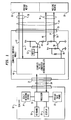
- FIG. 1 is a schematic block diagram of a typical postage scale having a postage value determining system processor and a converter interface and schematically illustrates the unique portion of the interface which provides trip capability for controlling one or more peripheral devices such as a postage meter and mailing machine.
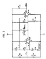
- FIG. 2 is a circuit diagram of a reset unit which may be used in the converter and trip enabling device illustrated in FIG. 1.
- the reference number 12 indicates a processor controlled stand-alone postage scale.
- the scale 12 is adapted to calculate the postage or other transportation charges required to transport an article. In most instances, transportation charges are based upon the article weight, class of transportation and, with respect to certain classes, distance to destination (zone).
- the scale 12 includes a weighing device 14 having a tray or platform adapted to receive the article to be mailed.
- the weighing device 14 is interconnected to a main system processor 16.
- the system processor 16 is programmed to compute the requisite postage or other transportation charges for an article placed upon the platform.
- the data necessary for the determination of article postage e.g. destination operands, class of transportation operands, etc. may be entered at a keyboard 18 and processor 16. Keyboard and calculated information may be indicated at a display 20.
- the system processor 16 determines the requisite postage by reference to a postage rate PROM 22 and provides a signal to the display 20 for indicating the calculated postage amount.
- the postage machine may be provided as a stand alone unit which need not incorporate an interface for communication with mailing system peripheral devices.
- a converter interface 24 is provided as a separate and discrete self contained plug-in module.
- the converter module is so constructed as to provide communications links between the postage scale 12 and an electronic postage meter 26 and mailing machine 28.
- the processor controlled stand alone postage scale may be programmed to communicate in standard serial RS-232 protocol, while the electronic postage meter 26 and its system processor may be programmed to communicate in the Echoplex format.
- the computer interface module 24 is connected to the scale 12 by a cable 30 and RS-232 connector 32.
- the connector 32 on the converter interface module 24 may be an RS-232 9 pin D shell sub miniature shielded connector. It will be appreciated that other equivalent connectors may be used.
- the connector at the scale 12 may be a similar connector.
- the computer interface module is connected to the postage meter 26 and mailing machine 28 by a cable 34.
- the cable 34 is bifurcated and divides at a Y to form a postage meter cable 36 and a mailing machine cable 38.
- the mailing machine may comprise a base unit that imprints the postage on an envelope or on a paper tape, as is well known.
- the postage meter mounts on the base unit to constitute a mailing machine assemblage.
- the cable 34 may connect to the converter interface module housing 24 via another RS-232 9 pin D shell sub-miniature shielded connector 35. Again, any equivalent connector may be used.
- the connectors at the postage meter 26 and mailing machine 28 may be similar connectors.
- the converter interface housing preferably comprises a plastic or metal housing of small size, such as, for example, 4 by 3 by 1 inches.
- the connectors 32 and 35 are preferably axially aligned at opposite ends of the housing for convenience of disposition of the cables and converter interface module.
- the converter interface module contains an Echoplex/RS-232 converter and micro-controller 40 of the type described in detail in the above mentioned Duwel and Soderberg patent No. 4,535,421. Power for the converter micro-controller and remainder of the module housed circuitry to be described is preferably obtained from the host device 12. While the exemplary host which is here described as comprising a postage scale, other host devices could equally well be utilized. Thus, the host may constitute a host computer in stand alone form or incorporated in other products. An externally visible display light, such as an LED, is preferably provided to indicate that the converter interface is powered; when connected with a meter, the light is flashing. The power drawn by the converter interface module should be small, preferably no more than 150 milliamperes.
- the converter interface includes an Echoplex/RS-232 converter micro-controller 40.
- the converter micro-controller 40 comprises two one-way simplex circuits diagrammatically shown at 42 and 44. As will be understood, one simplex circuit is used for the transmission of data from a device and the other is used for reception of information by the device.
- Communication between the converter micro-controller 40 and postage meter 26 is typically at 9.6 KBaud with no application layer formatting performed by the converter.
- the communication with the host or postage scale interface 12 is also typically 9.6 KBaud RS-232, full duplex, with the host computer or processor configured as a DTE (Data Terminal Equipment) device.
- DTE Data Terminal Equipment
- the trip lead 46 connects through a 10 ohm resistor 48 pull-up to the current limited supply voltage Vcc, which typically may be 5 volts DC.
- the pull-up resistor 48 should have an adequate wattage rating, such as 1/4 watt minimum, to protect against a potential short condition of the trip lead 46 to ground by the trip solenoid of the postage meter.
- the trip lead resistor 48 connects to the collector of a pnp transistor 50 having its emitter connected to supply voltage Vcc.
- the base of the transistor is connected to the reset terminal of the converter micro-controller 40. This terminal is also connected to a conventional protective circuit 52 to insure that an inadvertent trip does not occur in a POR (Power-On-Reset) condition.
- POR Power-On-Reset
- the TripRet lead 54 is connected through a similar resistor 56 to the collector of an npn transistor 58.
- the emitter of the transistor 58 is grounded.
- the transistor base is connected to the collector of a second npn transistor 60 having a grounded emitter.
- the base of transistor 60 is connected to the converter micro-controller 40.
- the firmware in the micro-controller 40 examines the contents of scale messages from the host 12 for a trip command. Upon receipt of this command, the micro-processor will assert the TripRet command signal for a specified time period, such as for example 100-15 mS. Upon de-assertion of the TripRet signal, the micro-controller will resume normal operation allowing the meter's response to the Trip signal to be passed by the converter micro-controller to the scale.
- the external tape request is generated upon receipt of the TRIP METER command from the RS-232 host 12 with no consideration of the current state of the Echoplex communication port. The converter micro-controller will not convert and transmit this TRIP METER command to the Echoplex meter. The converter micro-controller will discard all messages initiated while the TRIPRET signal is asserted.
- the transistor 58 When the TRIPRET signal is asserted the transistor 58 goes conductive and presents an open collector path to ground to the line 54.
- the tape request signal is generated by sinking current through this open collector output for the specified duration. This creates a negative going pulse to the mailing machine 28 and initiates a tape request and trip sequence which results in the imprinting of a postage value.
- FIG. 2 A typical circuit for the reset unit is shown in FIG. 2.
- the reset unit simply insures that powering up does not result in an inadvertent trip.
- a reset signal is delivered to the converter micro-controller, a signal is simultaneously sent to the transistor 50 to render that transistor non-conductive or open to disconnect the trip line 46 from the supply Vcc. When this occurs there is no supply voltage difference existing on the lines 46 and 54 and no current flow.
- the invention provides in a compact accessory form, a transparent interface between a first device utilizing serial communication, such as RS-232, and a second device utilizing Echoplex communication, which enables real time data communication, and which provides the capability to trip a mailing machine or the like.
- serial communication such as RS-232
- Echoplex communication which enables real time data communication, and which provides the capability to trip a mailing machine or the like.
Landscapes
- Physics & Mathematics (AREA)
- General Physics & Mathematics (AREA)
- Engineering & Computer Science (AREA)
- Computer Hardware Design (AREA)
- General Engineering & Computer Science (AREA)
- Devices For Checking Fares Or Tickets At Control Points (AREA)
- Communication Control (AREA)
Applications Claiming Priority (2)
| Application Number | Priority Date | Filing Date | Title |
|---|---|---|---|
| US910868 | 1992-07-01 | ||
| US08/910,868 US6076081A (en) | 1997-08-13 | 1997-08-13 | Protocol converter with peripheral machine trip capability |
Publications (2)
| Publication Number | Publication Date |
|---|---|
| EP0898248A2 true EP0898248A2 (fr) | 1999-02-24 |
| EP0898248A3 EP0898248A3 (fr) | 2000-06-21 |
Family
ID=25429430
Family Applications (1)
| Application Number | Title | Priority Date | Filing Date |
|---|---|---|---|
| EP98115256A Withdrawn EP0898248A3 (fr) | 1997-08-13 | 1998-08-13 | Convertisseur de protocole amélioré avec capacité de déclenchement des machines périphériques |
Country Status (3)
| Country | Link |
|---|---|
| US (1) | US6076081A (fr) |
| EP (1) | EP0898248A3 (fr) |
| CA (1) | CA2244923C (fr) |
Cited By (2)
| Publication number | Priority date | Publication date | Assignee | Title |
|---|---|---|---|---|
| US6076081A (en) * | 1997-08-13 | 2000-06-13 | Pitney Bowes Inc. | Protocol converter with peripheral machine trip capability |
| EP1113402A1 (fr) * | 1999-12-31 | 2001-07-04 | Pitney Bowes Inc. | Une interface intelligente de câbles et procédé de réalisation |
Families Citing this family (12)
| Publication number | Priority date | Publication date | Assignee | Title |
|---|---|---|---|---|
| US6378012B1 (en) * | 1998-10-29 | 2002-04-23 | Edward R. Bass | Interface with data transmission mode from weighing scale to one or more peripheral devices and mailing machine tripping mode determined by individual peripheral device protocol |
| US6334119B1 (en) * | 1998-11-13 | 2001-12-25 | Pitney Bowes Inc. | Method and system for selectively interacting with a postage meter provided on an inserter system |
| US20020128986A1 (en) * | 2001-02-23 | 2002-09-12 | Peter Stutz | Communication system for franking system |
| US20020169728A1 (en) * | 2001-02-23 | 2002-11-14 | Christian Moy | Modular franking system |
| US20020133471A1 (en) * | 2001-02-23 | 2002-09-19 | Fetneh Eskandari | Configuration enablement of franking system |
| US7124218B2 (en) * | 2001-09-27 | 2006-10-17 | International Business Machines Corporation | System and method for providing character interactive input/output |
| DE10162986B4 (de) * | 2001-12-20 | 2004-01-15 | Siemens Ag | Anbindung von Netzwerken mit unterschiedlichen Protokollen |
| US20040215828A1 (en) * | 2002-06-03 | 2004-10-28 | Yinghe Li | Interconnecting proxy, system and method of interconnecting networks using different protocols |
| US7457311B2 (en) * | 2004-08-31 | 2008-11-25 | Honeywell International Inc. | Portable communication interface device |
| US7958291B2 (en) * | 2006-10-10 | 2011-06-07 | Atmel Rousset S.A.S. | Supplemental communication interface |
| US20080104575A1 (en) * | 2006-10-31 | 2008-05-01 | Motorola, Inc. | Agent for implementing automated compatibility test |
| US7845568B2 (en) * | 2007-05-09 | 2010-12-07 | Atmel Rousset S.A.S. | Managing power and timing in a smart card device |
Citations (3)
| Publication number | Priority date | Publication date | Assignee | Title |
|---|---|---|---|---|
| US4399538A (en) * | 1981-04-30 | 1983-08-16 | Pitney Bowes Inc. | Control system for inhibiting processing communications |
| US4410961A (en) * | 1981-02-17 | 1983-10-18 | Pitney Bowes Inc. | Interface between a processor system and peripheral devices used in a mailing system |
| US4692870A (en) * | 1984-12-20 | 1987-09-08 | Pitney Bowes Inc. | General purpose processor module for mailroom equipment |
Family Cites Families (14)
| Publication number | Priority date | Publication date | Assignee | Title |
|---|---|---|---|---|
| US4308579A (en) * | 1979-02-21 | 1981-12-29 | Pitney Bowes Inc. | Multiprocessor parcel postage metering system having serial data bus |
| US4525785A (en) * | 1979-10-30 | 1985-06-25 | Pitney Bowes Inc. | Electronic postage meter having plural computing system |
| US4301507A (en) * | 1979-10-30 | 1981-11-17 | Pitney Bowes Inc. | Electronic postage meter having plural computing systems |
| US4498187A (en) * | 1979-10-30 | 1985-02-05 | Pitney Bowes Inc. | Electronic postage meter having plural computing systems |
| US4466079A (en) * | 1981-02-17 | 1984-08-14 | Pitney Bowes Inc. | Mailing system peripheral interface with communications formatting memory |
| US4535421A (en) * | 1983-07-05 | 1985-08-13 | Pitney Bowes Inc. | Universal real time transparent asynchronous serial/echoplex converter |
| US5206812A (en) * | 1987-04-03 | 1993-04-27 | Alcatel Business Systems Limited | Franking machine |
| US5159684A (en) * | 1989-05-24 | 1992-10-27 | Pitney Bowes Inc. | Data communication interface integrated circuit with data-echoing and non-echoing communication modes |
| US5050078A (en) * | 1989-10-03 | 1991-09-17 | Pitney Bowes Inc. | Mail processing and accounting system with communication among processing units and data reformatting |
| US5009276A (en) * | 1990-01-16 | 1991-04-23 | Pitney Bowes Inc. | Electronic postal scale with multilingual operator prompts and report headings |
| US5202914A (en) * | 1990-09-13 | 1993-04-13 | Pitney Bowes Inc. | System for resetting a postage meter |
| US5737426A (en) * | 1994-12-13 | 1998-04-07 | Pitney Bowes Inc. | Remote and secure feature enabling for an electronic postage meter |
| US5666292A (en) * | 1994-12-13 | 1997-09-09 | Pitney Bowes Inc. | External interface unit having message routing and protocol conversion |
| US6076081A (en) * | 1997-08-13 | 2000-06-13 | Pitney Bowes Inc. | Protocol converter with peripheral machine trip capability |
-
1997
- 1997-08-13 US US08/910,868 patent/US6076081A/en not_active Expired - Fee Related
-
1998
- 1998-08-12 CA CA002244923A patent/CA2244923C/fr not_active Expired - Fee Related
- 1998-08-13 EP EP98115256A patent/EP0898248A3/fr not_active Withdrawn
Patent Citations (3)
| Publication number | Priority date | Publication date | Assignee | Title |
|---|---|---|---|---|
| US4410961A (en) * | 1981-02-17 | 1983-10-18 | Pitney Bowes Inc. | Interface between a processor system and peripheral devices used in a mailing system |
| US4399538A (en) * | 1981-04-30 | 1983-08-16 | Pitney Bowes Inc. | Control system for inhibiting processing communications |
| US4692870A (en) * | 1984-12-20 | 1987-09-08 | Pitney Bowes Inc. | General purpose processor module for mailroom equipment |
Non-Patent Citations (1)
| Title |
|---|
| BLITZER: "basic pulse circuits" 1964 , MCGRAW-HILL , NEW YORK XP002135927 * page 275 - page 278 * * |
Cited By (2)
| Publication number | Priority date | Publication date | Assignee | Title |
|---|---|---|---|---|
| US6076081A (en) * | 1997-08-13 | 2000-06-13 | Pitney Bowes Inc. | Protocol converter with peripheral machine trip capability |
| EP1113402A1 (fr) * | 1999-12-31 | 2001-07-04 | Pitney Bowes Inc. | Une interface intelligente de câbles et procédé de réalisation |
Also Published As
| Publication number | Publication date |
|---|---|
| CA2244923C (fr) | 2004-05-11 |
| US6076081A (en) | 2000-06-13 |
| EP0898248A3 (fr) | 2000-06-21 |
| CA2244923A1 (fr) | 1999-02-13 |
Similar Documents
| Publication | Publication Date | Title |
|---|---|---|
| US6076081A (en) | Protocol converter with peripheral machine trip capability | |
| CA1159563A (fr) | Affranchisseuse electronique a plusieurs systemes de comptage | |
| US4365293A (en) | Serial communications bus for remote terminals | |
| US4410961A (en) | Interface between a processor system and peripheral devices used in a mailing system | |
| US4603400A (en) | Mailing system interface interprocessor communications channel | |
| US4430716A (en) | Postage value determining scale with expandable memory port | |
| US4787046A (en) | Mailing system having a capability for one-step postage metering | |
| US4422148A (en) | Electronic postage meter having plural computing systems | |
| CA1227575A (fr) | Convertisseur serie-echoplex asynchrone transparent universel fonctionnant en temps reel | |
| US4271470A (en) | Serial data bus for use in a multiprocessor parcel postage metering system | |
| EP0125526B1 (fr) | Système de machine d'affranchissement électronique | |
| US4642791A (en) | Interface for mailing system peripheral devices | |
| US5206812A (en) | Franking machine | |
| EP0088429B1 (fr) | Machine à affranchir à mémoire non-volatile pour conserver un numéro de série | |
| US4525785A (en) | Electronic postage meter having plural computing system | |
| EP0164584A1 (fr) | Appareil d'enregistrement des ventes | |
| US4583195A (en) | Mailing system interface between a scale system processor and a serial data bus which interconnects peripheral subsystems | |
| US4498187A (en) | Electronic postage meter having plural computing systems | |
| US6378012B1 (en) | Interface with data transmission mode from weighing scale to one or more peripheral devices and mailing machine tripping mode determined by individual peripheral device protocol | |
| US4569022A (en) | Meter selection for drop shipment mailing system | |
| US5680403A (en) | Multiplex serial data communications with a single UART for a postage meter mailing machine system | |
| US6502143B1 (en) | Intelligent interface cable assembly and method of providing the same | |
| US7057117B2 (en) | Combination balance and cash register | |
| GB2180126A (en) | Inter-bus system | |
| CN108446194A (zh) | 一种综合检测仪控制系统及控制方法、专用计算机 |
Legal Events
| Date | Code | Title | Description |
|---|---|---|---|
| PUAI | Public reference made under article 153(3) epc to a published international application that has entered the european phase |
Free format text: ORIGINAL CODE: 0009012 |
|
| AK | Designated contracting states |
Kind code of ref document: A2 Designated state(s): DE FR GB |
|
| AX | Request for extension of the european patent |
Free format text: AL;LT;LV;MK;RO;SI |
|
| PUAL | Search report despatched |
Free format text: ORIGINAL CODE: 0009013 |
|
| AK | Designated contracting states |
Kind code of ref document: A3 Designated state(s): AT BE CH CY DE DK ES FI FR GB GR IE IT LI LU MC NL PT SE |
|
| AX | Request for extension of the european patent |
Free format text: AL;LT;LV;MK;RO;SI |
|
| RIC1 | Information provided on ipc code assigned before grant |
Free format text: 7G 07B 17/02 A, 7G 06F 13/42 B |
|
| 17P | Request for examination filed |
Effective date: 20001213 |
|
| AKX | Designation fees paid |
Free format text: DE FR GB |
|
| 17Q | First examination report despatched |
Effective date: 20071220 |
|
| STAA | Information on the status of an ep patent application or granted ep patent |
Free format text: STATUS: THE APPLICATION IS DEEMED TO BE WITHDRAWN |
|
| 18D | Application deemed to be withdrawn |
Effective date: 20120301 |