EP0898046A2 - Method and apparatus for releasably connecting a wireline to a downhole tool - Google Patents
Method and apparatus for releasably connecting a wireline to a downhole tool Download PDFInfo
- Publication number
- EP0898046A2 EP0898046A2 EP98306618A EP98306618A EP0898046A2 EP 0898046 A2 EP0898046 A2 EP 0898046A2 EP 98306618 A EP98306618 A EP 98306618A EP 98306618 A EP98306618 A EP 98306618A EP 0898046 A2 EP0898046 A2 EP 0898046A2
- Authority
- EP
- European Patent Office
- Prior art keywords
- wireline
- connector
- downhole tool
- releasing
- shaft
- Prior art date
- Legal status (The legal status is an assumption and is not a legal conclusion. Google has not performed a legal analysis and makes no representation as to the accuracy of the status listed.)
- Granted
Links
- 238000000034 method Methods 0.000 title claims abstract description 22
- 239000000463 material Substances 0.000 claims abstract description 65
- 239000007787 solid Substances 0.000 claims abstract description 4
- 239000004020 conductor Substances 0.000 claims description 37
- 239000002360 explosive Substances 0.000 claims description 20
- 230000007246 mechanism Effects 0.000 claims description 11
- 230000008018 melting Effects 0.000 claims description 11
- 238000002844 melting Methods 0.000 claims description 11
- 230000003213 activating effect Effects 0.000 claims description 8
- 239000012530 fluid Substances 0.000 claims description 6
- 238000010438 heat treatment Methods 0.000 claims description 4
- 239000006023 eutectic alloy Substances 0.000 claims description 3
- 239000004332 silver Substances 0.000 claims description 2
- 230000001419 dependent effect Effects 0.000 claims 4
- 229910001316 Ag alloy Inorganic materials 0.000 claims 1
- 229910001128 Sn alloy Inorganic materials 0.000 claims 1
- 230000004913 activation Effects 0.000 claims 1
- 230000004044 response Effects 0.000 abstract description 2
- 230000035939 shock Effects 0.000 description 6
- 230000008901 benefit Effects 0.000 description 4
- 230000008878 coupling Effects 0.000 description 3
- 238000010168 coupling process Methods 0.000 description 3
- 238000005859 coupling reaction Methods 0.000 description 3
- 229910052751 metal Inorganic materials 0.000 description 3
- 239000002184 metal Substances 0.000 description 3
- 241000282472 Canis lupus familiaris Species 0.000 description 2
- 238000010586 diagram Methods 0.000 description 2
- 230000005496 eutectics Effects 0.000 description 2
- 239000000155 melt Substances 0.000 description 2
- 241000251468 Actinopterygii Species 0.000 description 1
- 229910000831 Steel Inorganic materials 0.000 description 1
- ATJFFYVFTNAWJD-UHFFFAOYSA-N Tin Chemical compound [Sn] ATJFFYVFTNAWJD-UHFFFAOYSA-N 0.000 description 1
- 230000002411 adverse Effects 0.000 description 1
- 229910045601 alloy Inorganic materials 0.000 description 1
- 239000000956 alloy Substances 0.000 description 1
- 230000015572 biosynthetic process Effects 0.000 description 1
- 230000006835 compression Effects 0.000 description 1
- 238000007906 compression Methods 0.000 description 1
- 230000006378 damage Effects 0.000 description 1
- 230000007812 deficiency Effects 0.000 description 1
- 238000005474 detonation Methods 0.000 description 1
- 238000005553 drilling Methods 0.000 description 1
- 230000000694 effects Effects 0.000 description 1
- 238000000605 extraction Methods 0.000 description 1
- 229910000743 fusible alloy Inorganic materials 0.000 description 1
- 239000010720 hydraulic oil Substances 0.000 description 1
- 239000007788 liquid Substances 0.000 description 1
- 238000004519 manufacturing process Methods 0.000 description 1
- 230000004048 modification Effects 0.000 description 1
- 238000012986 modification Methods 0.000 description 1
- 239000003921 oil Substances 0.000 description 1
- 230000002028 premature Effects 0.000 description 1
- 230000008439 repair process Effects 0.000 description 1
- 230000000717 retained effect Effects 0.000 description 1
- 230000009528 severe injury Effects 0.000 description 1
- 229910052709 silver Inorganic materials 0.000 description 1
- 239000010959 steel Substances 0.000 description 1
- 230000007704 transition Effects 0.000 description 1
Images


Classifications
-
- E—FIXED CONSTRUCTIONS
- E21—EARTH DRILLING; MINING
- E21B—EARTH DRILLING, e.g. DEEP DRILLING; OBTAINING OIL, GAS, WATER, SOLUBLE OR MELTABLE MATERIALS OR A SLURRY OF MINERALS FROM WELLS
- E21B17/00—Drilling rods or pipes; Flexible drill strings; Kellies; Drill collars; Sucker rods; Cables; Casings; Tubings
- E21B17/02—Couplings; joints
- E21B17/04—Couplings; joints between rod or the like and bit or between rod and rod or the like
- E21B17/06—Releasing-joints, e.g. safety joints
-
- E—FIXED CONSTRUCTIONS
- E21—EARTH DRILLING; MINING
- E21B—EARTH DRILLING, e.g. DEEP DRILLING; OBTAINING OIL, GAS, WATER, SOLUBLE OR MELTABLE MATERIALS OR A SLURRY OF MINERALS FROM WELLS
- E21B17/00—Drilling rods or pipes; Flexible drill strings; Kellies; Drill collars; Sucker rods; Cables; Casings; Tubings
- E21B17/02—Couplings; joints
- E21B17/023—Arrangements for connecting cables or wirelines to downhole devices
-
- E—FIXED CONSTRUCTIONS
- E21—EARTH DRILLING; MINING
- E21B—EARTH DRILLING, e.g. DEEP DRILLING; OBTAINING OIL, GAS, WATER, SOLUBLE OR MELTABLE MATERIALS OR A SLURRY OF MINERALS FROM WELLS
- E21B17/00—Drilling rods or pipes; Flexible drill strings; Kellies; Drill collars; Sucker rods; Cables; Casings; Tubings
- E21B17/02—Couplings; joints
- E21B17/028—Electrical or electro-magnetic connections
-
- E—FIXED CONSTRUCTIONS
- E21—EARTH DRILLING; MINING
- E21B—EARTH DRILLING, e.g. DEEP DRILLING; OBTAINING OIL, GAS, WATER, SOLUBLE OR MELTABLE MATERIALS OR A SLURRY OF MINERALS FROM WELLS
- E21B23/00—Apparatus for displacing, setting, locking, releasing, or removing tools, packers or the like in the boreholes or wells
- E21B23/14—Apparatus for displacing, setting, locking, releasing, or removing tools, packers or the like in the boreholes or wells for displacing a cable or cable-operated tool, e.g. for logging or perforating operations in deviated wells
Abstract

Description
- The present invention relates to method and apparatus for releasably connecting a wireline to a downhole tool. More particularly, the present invention relates to wireline connections for cable heads and more particularly to a release for releasing the wireline from the cable head.
- Wireline operations are carried out in oil and gas wells for conveying tools downhole in the well. A wide variety of downhole tools may be supported on a wireline including tools to perform logging, setting and retrieving operations. The tools typically comprise a combination of different tubular members threaded together to form a working unit which is manipulated from the surface via the wireline. Although tools may be conveyed downhole on a tubing string which can withstand substantially higher extraction forces than a wireline, oftentimes a wireline is preferred because it saves substantial rig time in conveying tools downhole and positioning them within the well. A release is typically provided at the cable head, which connects the tools to the wireline, to permit the wireline to be disconnected from the tools such as when the tools become stuck downhole.
- The safe pull of the wireline is a pull which does not exceed one-half the breaking strength of the wireline. When a tension is placed on the wireline which is over 50% of its break point, then problems begin to occur with the electrical conductors in the wireline. Also, there is the danger of breaking the wireline.
- A typical wireline release is the use of a mechanical weak point in the connection between the wireline and the cable head. Typically, this is a metal member which is designed to break upon a predetermined pull on the wireline. A safety margin is also required for the mechanical weak point and typically equals 66% of the amount of predetermined pull required to break the weak point and achieve a mechanical release. The correct conventional mechanical weak point must be calculated and installed prior to running the cable head and tools into the borehole on the wireline
- Thus, there are two limitations in using the typical conventional mechanical weak point release, one is the strength of the wireline itself and the other is the strength of the mechanical weak point. Assuming the cable head is located at the bottom of the borehole, the safe pull of the wireline is the lesser of 50% of the breaking strength of the wireline or 66% of the strength of the mechanical weak point plus the weight of the wireline suspended in the well. For example, assuming a 20,000 foot well, and a wireline having a break point of 22,000 pounds and a weight of 300 pounds per foot, the safe pull for the wireline is 11,000 pounds and the weight of the wireline will be approximately 6,000 pounds. Also, assuming the mechanical weak point is set at 5,000 pounds, then the safe point of the mechanical weak point is 66% of 5,000 or approximately 3,300 pounds. Thus, the limitation on the amount of pull which can be placed on the wireline is 9,300 pounds, i.e. 6,000 pounds for the weight of the wireline and 3,300 pounds for the safe pull of the mechanical weak point. In this example, the maximum pull, i.e. safe pull, on the wireline can be only 9,300 pounds. This example is over simplified because the friction of the system was not taken into account. In particular, if the cable head and tools are in a deviated hole, there may be a pull of 9,300 pounds at the surface with only 1,000 pounds being pulled on the cable head and tools because of friction on the wireline.
- Various other apparatus and methods have been provided for releasing the wireline from the cable head and tools. One prior art method of releasing the wireline includes the use of a spring set at a particular tension. Once the force on the spring is exceeded, the wireline is released. This release still requires that the amount of load required to release the wireline be predetermined prior to lowering the cable head into the well. If the spring tension is exceeded, there can be a premature release of the cable head.
- Another type of prior art release relies primarily on shear pins. Since wireline has fairly low tensile capabilities with respect to tubing, the shear screw or screws used in the prior art require a fairly low shear rating. This low shear rating was necessary to prevent damage to the wireline from excessive tensile stress should the dowmhole tool become stuck in the wellbore. Problems are encountered with shear screws having a low failure point because they are exposed to various cyclical forces which tend to affect their ultimate shear rating. The shear screws are exposed to fluids in the well which over time can affect the inherent strength of the shear screws or pins making them susceptible to failure at stresses below their rated failure point. Unexpected release can significantly delay operations, thereby costing significant sums. An unexpected release can also result in the loss of dowmhole tools and in extreme cases can cause severe damage to the wellbore which requires substantial time and money to repair.
- It is not unusual for the cable head and tools to become stuck as they are being retrieved from the well. For example, where the pressure in the borehole is greater than the pressure in the formation, the drilling fluids tend to cake on the interior of the casing causing the tool to become lodged as it is retrieved. Further, the longer that the cable head and tool are stuck, the more difficult the retrieval becomes. Thus, it is desirable to remove the cable head and tools as soon as possible and this may be best accomplished if a high tension may be placed on the wireline. However, where a mechanical type release is used requiring the setting of the safe pull at the surface prior to lowering into the well, the amount of pull which can be applied to the wireline is limited to the safe pull of the release mechanism. Because the mechanical release has been set at a low value to insure that the wireline can be detached from the cable head at the deepest portion of the well without exceeding the maximum safe pull on the wireline, and because the length of the wircline has been reduced since the wireline may now be at a higher elevation within the borehole, only a limited amount of the safe tensile load of the wireline may be used to dislodge the cable head and tools. Any greater pull may break the mechanical release and prematurely release the cable head and tool. Thus, it is desirable to have available the maximum amount of pull possible for retrieving the cable head and tool. Further, once the cable head becomes stuck using a conventional mechanical release, the amount of safe pull must be calculated based on the depth of the cable head in the well.
- Using the conventional mechanical release, a high tension must be placed on the cable to exceed the tensile strength and break the weak point. Upon breaking the mechanical release, a large shock is imparted to the cable head because of the large tension on the wireline. For example, when the cable head is stuck, the operator will fish for the tool with the wireline left in the hole. The operator lowers a grapple which grabs the top of the cable head or the tool body. Once the tools are grabbed, the operator wants to release the wireline and remove it from the hole. This makes it a lot easier to pull the tools and pipe out of the well. Thus, the operator places a large tension on the wireline to activate the mechanical release.
- Other apparatus and methods are used which do not require a mechanical break point setting. One method includes attaching at the surface a cutter tool which slides down the wireline cutting the wireline on impact at the connection of the wireline to the cable head. However, time is lost when attaching such a cutter tool since the blowout preventer has to be sealed across the wire to hold back well pressure while the tool is attached to the wireline. Another disadvantage is that the cutter tool may cut the wire prematurely if it hits a restriction on its way downhole.
- Another type of prior art release includes the use of bolts which are exploded to disconnect the wireline from the cable head. Explosive bolts have the advantage of allowing the application of tension on the wireline up to the amount of safe pull permitted for the wireline. However, one disadvantage is that once the signal to detonate the explosive bolts has been sent from the surface, the detonation cannot be terminated. There are concems that the explosive bolts will prematurely detonate accidentally releasing the cable head from the wireline. Further, many safety concems arise in using explosive bolts. A dangerous material must be used for exploding the bolts and thus requires an explosive device to be housed within the cable head. Also, there are safety issues in storing a cable head having an explosive device. Such a release system requires that many safety devices be used to ensure that adequate safety is provided.
- In yet still another prior art release, a spring loaded piston is used which can be activated by pressuring up the wellbore and applying the pressure to the piston. However, the release can be prematurely activated by encountering a higher pressure downhole. In particular, the deeper the cable head is lowered into the well, the higher the borehole pressure.
- In another prior art apparatus, the cable head includes a plurality of full diameter sections with one of the sections being released. However, a full diameter tubular member is more difficult to retrieve from the well.
- Major problems occur if the cable head and tools get stuck in the well and the wireline breaks upon pulling on the wireline with too much tension. Breaking the wireline and dropping the wireline in the well greatly complicates the fishing operation to retrieve the tools.
- The present invention overcomes the deficiencies of the prior art.
- According to one aspect of the invention there is provided apparatus connecting a wireline to a downhole tool comprising: a connector adapted to connect the downhole tool to the wireline, the connector having a connected position connecting the wireline to the downhole tool and an unconnected position releasing the wireline from the downhole tool; and a non-explosive release means for maintaining the connector in said connected position and for actuating the connector to said unconnected position to release the wireline from the downhole tool, said release means being activatable electrically by the wireline.
- The connector may be any form of connecting means suitable for connecting the wireline to the downhole tool.
- According to another aspect of the invention there is provided a method of releasing a wireline from a downhole tool, comprising: running the wireline and the downhole tool into a well, the wireline and the downhole tool being connected by a non-explosive release mechanism; and activating the non-explosive release mechanism with an electrical signal to release the wireline from the downhole tool.
- According to another aspect of the invention there is provided an apparatus for releasably connecting a wireline to a downhole tool, comprising: a connector adapted for connection to the downhole tool and adapted for releasable connection to the wireline, said connector having a connected position connecting the wireline and an unconnected position releasing the wireline; and a non-explosive release disposed on said connector and maintaining said connector in the connected position, said non-explosive release adapted to be electrically connected to the wireline, said release electrically activated by the wireline to actuate said connector to said unconnected position.
- According to another aspect of the invention there is provided an apparatus for releasably connecting a wireline to a downhole tool, comprising: connector means for connecting the downhole tool to the wireline, said connector means having a connected position connecting the wireline to the downhole tool and an unconnected position releasing the wireline from the downhole tool; and release means being non-explosive for maintaining said connector in said connected position and for actuating said connector means to said unconnected position for releasing the wireline from the downhole tool, said release means being activated electrically by the wireline.
- According to another aspect of the invention there is provided an apparatus for releasably connecting a wireline to a downhole tool, comprising: a housing adapted for connection to the downhole tool; a connector disposed in said housing and having a connected position connecting said housing with the wireline and a release position releasing the wireline from said housing; a fusible material maintaining said connector in the connected position while said materials is in its solid state; and a heater for changing said fusible material to a fluid state and actuating said connector to said release position to disconnect the wireline from said housing.
- According to another aspect of the invention there is provided an apparatus for connecting a wireline cable to a cable head comprising: a tubular housing; a first member having a first bore with a chamber, said chamber forming an annular shoulder; a shaft extending into said first bore and chamber and having an enlarged diameter portion disposed within said chamber; a fusible material disposed about said shaft in said chamber between said shoulder and said enlarged portion in a latched position; a second member disposed within said housing and having a second bore, said second bore forming an internal profile; said shaft extending through said second bore and having a releasable connector disposed on the end of said shaft; said releasable connector interacting with said internal profile in said latched position connecting the wireline to the housing and in an unlatched position releasing the wireline; and a heater disposed around said fusible material melting said fusible material and allowing said shaft to move said connector to said unlatched position.
- According to another aspect of the invention there is provided a method of releasing a wireline from a downhole tool, comprising: supporting a downhole tool in a well on a wireline having a breaking strength; connecting the wireline to the downhole tool with a non-explosive release mechanism; pulling on the wireline with a tension equal to one half the breaking strength without releasing the wireline; sending an electrical signal to the non-explosive release mechanism; and releasing the wireline from the downhole tool.
- According to another aspect of the invention there is provided a method of releasing a wireline from a downhole tool, comprising: running a downhole tool into the well with a latch; connecting electrically a heater in the downhole tool to the wireline; turning on the heater from the wireline to heat a fusible material; melting the fusible material allowing relative movement of said latch within said downhole tool; and releasing the wireline from the latch.
- According to another aspect of the invention there is provided a wireline method for use in a wellbore and incorporating a wireline having a releasing device which includes a latch mounted on the end of a shaft, the latch releasably connectable to said wireline, a material maintaining the shaft and thus the latch in a latched position and a heater for melting said material, said method comprising: connecting said releasing device to said downhole tool and to said wireline; extending said wireline, with said releasing device and said downhole tool attached thereto, into the wellbore; and electrically activating the heater and heating the fusible material to allow said shaft to shift said latch to an unlatched position thereby operating the releasing device downhole.
- In an embodiment of the invention, the wireline release includes a shaft having one end releasably connected to the end of the wireline by a connector and being held in the latched position by a fusible material ring. Upon activating heaters in the cable head from the surface via conductors in the wireline, the fusible material ring is melted allowing the shaft, under the tension of the wireline, to shift to an unlatched position whereby the connector releases the wireline from the shaft and cable head. The connector is a collet connector having a plurality of individual members which, in the latched position are biased into the connection with the end of the wireline and are then released upon being shifted to the unlatched position where the collets move to a disengaged position.
- One of the advantages of the release of the present invention is that the only limitation on the safe pull of the wireline is the breaking strength of the wireline. No mechanical weak point is used having a predetermined break strength. Thus, a much greater tension may be placed on the wireline from the surface to retrieve a cable head and tools which have become stuck in the well.
- Another advantage of the release of the present invention is that it is not an automatic release and will only release the wireline upon command from the operator at the surface. Further, the release is reusable.
- The apparatus according to the invention will hereinafter be referred to as a cable head.
- The cable head of the present invention may provide redundant circuitry and conductor utilization to ensure the ability to heat the fusible material and activate the release. Two latching relays are used to switch separate electrical lines to the heaters. Further, the heater may include two different heater coils and the wireline provides four conductors to power the heater coils. Also, the conductors may be isolated by diodes from the heater coils to keep a shorted line from disabling one of the heaters.
- The cable head of the present invention also includes safeguards against accidental release. The use of the fusible material as release mechanism is simple and safe.
- The cable head of the present invention has the further advantage of reduced shock upon release of the wireline as compared to shock caused by the breaking of a convention weak point. The breaking strength of a convention mechanical weak point must be exceeded while the present invention only requires a minimum tension on the wireline to operate the release.
- Reference is now made to the accompanying drawings, in which:
- Figure 1 is a schematic view illustrating an embodiment of a cable head according to the present invention disposed within the borehole of a well;
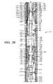
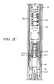
- Figures 2A-D are a cross-section of the cable head according to the present invention suspended by a wireline and supporting a string of tools;
- Figures 3A and B illustrate an electrical diagram showing an electric circuit for activating heaters; and
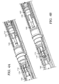
- Figures 4A and B illustrate the cable head according to the present invention in both the latched and unlatched positions.
-
- Referring initially to Figure 1, there is shown schematically a
cable head 10 supported by awireline 12 from arig 14 at thesurface 16. Thecable head 10 supports atool string 18 disposed adjacent aproduction zone 22 located, as for example, near the bottom 24 ofborehole 20. Thewireline 12 is disposed around one ormore sheave wheels 26 to awireline vehicle 28 having instrumentation well known in the art. - The
rig 14 includes a load cell (not shown) which determines the amount of pull onwireline 12 at the surface of theborehole 20. The instrumentation ofwireline vehicle 28 includes a safety valve which controls the hydraulic pressure that drives thedrum 29 on thewireline vehicle 28 which reels up thewireline 12. The safety valve is adjusted to a pressure such that the drum can only impart a small amount of tension to thewireline 12 over and above the tension necessary to retrieve thewireline 12,cable head 10, and tool string 1S from theborehole 20. The safety valve is typically set a few hundred pounds above the amount of desired safe pull on thewireline 12 such that once that limit is exceeded, further pull on the wireline is prevented. -
Wireline 12, sometimes referred to as a cable, typically includes a plurality of electrical conductors extending from thewireline vehicle 28 to thecable head 10, all well known in the art. One such type ofwireline 12 includes an inner core of seven electrical conductors covered by an insulating wrap. An inner and outer steel annor sheath is then wrapped in a helix in opposite directions around the conductors. The electrical conductors are used for communicating power and telemetry between thewireline vehicle 28 andtool string 18. - Referring now to Figures 2A-D,
wireline 12 is shown supportingcable head 10 which in tum threadingly supportstool string 18, such as logging, setting and retrieving tools, at its lower end.Cable head 10 includes anouter housing 30 made up of a connectinghead 32, alatch housing 34, anextension housing 36, and apressure housing 38. Connectinghead 32 includes acoupling sub 40 threadably mounted at 44 on themain body 42 ofhead 32. Couplingsub 40 includes threads for threaded connection at 46 to the upper end oflatch housing 34. A slottedspace 83 is provided inlatch housing 34 for receiving a support member (not shown).Extension housing 36 is threaded at 48 onto the lower end oflatch housing 34 andpressure housing 38 is threaded at 50 onto the lower end ofextension housing 36. The tool string IS is mounted at 52 onto the lower end ofpressure housing 38. - The lower end of
wireline 12 is connected to the upper end oflatch assembly 60 by means of aconnector assembly 54.Connector assembly 54 includes asplit sleeve 56 disposed within aretainer sleeve 58. The lower end ofsplit sleeve 56 is connected to anchormember 190. The lower end ofwireline 12 extends throughspring 64 which is attached to splitsleeve 56 byspring retainer 66. Thewireline 12 is disposed between the two halves ofsplit sleeve 56 with its terminal end feeding throughflanged head 68 disposed in therope socket 70 formed insleeve 56. Conical wedges are driven into the end of thewireline 12 between the armor sheaths to mechanically attach the terminal end ofwireline 12 toflanged head 68. The greater the tension onwireline 12, the greater the wedging effect of the two conical wedges. -
Retainer sleeve 58 slides oversplit sleeve 56 to retainspring retainer 66,flanged head 68, andanchor member 190. The lower end ofsleeve 56 has inwardly directed flanges which fit around theflanged head 62 ofanchor member 190.Anchor member 190 is connected to the upper end oflatch assembly 60.Dogs 67 andslot 69 insleeve 56 andhead 68, respectively, preventsleeve 56 from rotating with respect tohead 68. Relative rotation would twistconductors 74. Ascrew 59 and a retainingring 63 attachessleeves -
Slots 72 are provided in the lower end ofsplit sleeve 56 to allow theconductors 74 ofwireline 12 to pass throughaperture 72 for electrical connection with thecable head 10. The terminal end of eachindividual conductor 74 passes through an insulated boot orsleeve 78 for attachment to asocket connector 80.Socket connector 80 is attached toconnector 76 mounted in the upper end oflatch sleeve 90. -
Latch assembly 60 includes aninner housing 82 disposed withinouter housing 30. Atop sub 84 is keyed axially at 86 onto the upper end ofinner latch housing 82 to prevent rotation and is retained bycap screw 88. A feed throughlatch sub 90 is mounted on the upper end oftop sub 84.Latch sub 90 is generally cylindrical forming abore 92 having an uppercylindrical portion 94, a medial portion with a predetermined contoured,intemal profile 96, and first and secondenlarged diameter portions -
Internal profile 96 ofbore 92 includes an upperenlarged portion 102 forming astop shoulder 104 and a restricted diameter portion forming an inwardly facing upperannular shoulder 106. A lowerenlarged portion 108 also formsannular shoulder 106 at its upper end and has a lower restricted diameter portion forming an inwardly facing lowerannular shoulder 110. -
Top sub 84 is also generally cylindrical and has abore 112 therethrough.Bore 112 includes an upper smaller diameter bore 114 and a lower enlarged diameter bore 116. The upper end ofsub 84 includes a reduceddiameter nose 118 which is slidingly received within the first enlarged bore 97 oflatch sub 90. A retainer socket/washer 121 is disposed between an upwardly facingannular shoulder 119 formed bynose 118 and the downwardly facing shoulder formed by the transition between first and secondenlarged portions -
Latch 60 also includes ananchor sub 120 keyed within theinner latch housing 82.Anchor sub 120 has a tensile strength greater than the safe pull of thewireline 12.Anchor sub 120 includes aneck portion 122 and abore 124 extending throughneck 122 and into the body ofanchor sub 120. Alatch housing 130 is threaded at 136 ontoneck 122 ofanchor sub 120 and includes ablind bore 132 which is adapted to receive aseal plug 126.Seal plug 126 has an enlarged end forming anannular shoulder 128 which engages ashoulder 134 inlatch housing 130. Acoaxial bore 138 extends throughcounterbore 132 and has a reduced diameter.Seal plug 126 also includes abore 142 which is coaxial withbore 138. Counter bore 132 and sealplug 126 form achamber 140. -
Latch assembly 60 includes alatch shaft 100 which extends fromsub 120 to latchsub 90.Shaft 100 extends throughbore 124 inanchor sub 120, throughbore 142 inseal plug 126, throughchamber 140 of counter bore 132, through bore 13S inlatch housing 130, throughbore 112 intop sub 84, and intobore 92 oflatch sub 90.Shaft 100 includes anenlarged diameter portion 150 which forms a lobe or collar disposed withinchamber 140 oflatch housing 130. Thecollar 150 has a interference fit with the inner wall ofmember 130 when at room temperature. -
Collar 150 divideschamber 140 into two sub chambers, 141 and 143. Theupper sub chamber 141 containsfusible material 160 when thelatch assembly 60 is in the latched position. In the latched position, the volume of thelower sub chamber 143 is substantially zero. When thefusible material 160 melts and theshaft 100 moves to the unlatched position, thecollar 150 moves along with it. The movement ofcollar 150 forces the melted fusible material to flow fromsub chamber 141 tosub chamber 143. The total volume ofchamber 140 remains constant and is the sum ofsub chambers sub chambers collar 150. - A ring of
fusible material 160 is disposed aroundshaft 100 and between the top 144 ofchamber 140 and the upwardly facingside 146 ofcollar 150.Material 160 is placed in compression bycollar 150 as tension is applied towireline 12. The preferred alloy forfusible material 160 is 96-1/2% tin and 3-1/2% silver. -
Shaft 100 includesflats 147 on its lower end which cooperate with a pin inanchor member 120 and also includesflats 148 which are keyed to arectangular slot 152 in astop block 154, fastened bycap screws 156 into the lower end oftop sub 84. These flats are provided to preventshaft 100 from rotating. The upper end ofshaft 100 includes anannular groove 158 forming ahead 162. - A latch connector, such as a
collet connector 170, is mounted around the upper end ofshaft 100.Collet connector 170 has a plurality of releasing elements in the form of individualelongated members 172, preferably S in number, for connectingshaft 100 to anchormember 190. Eachmember 172 includes an inwardly directedtine 174 which is received withinannular groove 158 ofshaft 100. Eachmember 172 includes atail 176 at its lower end and ahead 178 at its upper end having an inwardly directedflange 180 adapted to be received within agroove 182 formed inneck 184 ofanchor member 190.Flange 180 forms a downwardly facingarcuate shoulder 185 which tapers upwardly and inwardly for engagement with an upwardly facingannular shoulder 183 which tapers downwardly and outwardly. The tapered surfaces on shoulders 1S3, 185 form cooperating camsurfaces allowing members 172 to cam outwardly upon the release ofcollet connector 170 as hereinafter described in further detail. - In the lower latched position shown in Figure 2 A-D, the
shaft 100 is in its lowermost position. In its lowermost position,collet connector 170 is latched and connected to anchormember 190 due to the positioning of themembers 172 with respect to theinternal profile 96 oflatch sub 90. In the latched position,tail 176 bears againstshoulder 110 andhead 178 bears againstshoulder 106 thereby causingtine 174 to be maintained within groove 15S andflange 180 to be maintained withingroove 182 ofanchor member 190 withshoulders anchor member 190 is connected toconnector assembly 54 bysplit member 56,shaft 100 latchescable 12 tocable head 10. -
Latch assembly 60further inciudes heaters 192 comprised of two helically wound.independent coils fusible material 160.Heaters 192 are disposed within thebore 198 formed byinner latch housing 82,sub 84, andanchor sub 120. Helical coils 194, 196 are disposed around theexternal surface 202 oflatch housing 130 and preferably have a rectangular cross-section such that the inner surface of the coils are in contact with theexternal surface 202 oflatch housing 130 thereby providing good heat conductivity. One preferred type of coil is Model No. 125PS 30A 48A, 240 volt, 450 watt coil manufactured by Watlow manufacturing Co., Inc. of St. Louis, Missouri. -
Heaters 192 are electrically connected byconduits 204 to switchingchassis assembly 200 which is disposed withinbore 198 ofinner latch housing 82 belowanchor member 120. Heater coils 194, 196 are independent and are powered by separate conductors inwireline 12 so as to provide redundant heaters for heatingfusible material 160. - That portion of
bore 198housing heaters 192 and that portion of thebore 198 housing switchingchassis assembly 200 are maintained at atmospheric pressure. Thus, these chambers are sealed off from the borehole pressure by O-ring seal members Connector 172 is subjected to borehole pressure by means ofports latch sleeve 90 andcoupling sub 40, respectively.Connector 172 is also exposed to borehole pressure throughbore 92. Because theupper end 173 ofshaft 100 is subject to borehole pressure, it is necessary that the lower end ofshaft 100 also be subject to borehole pressure. Thus,ports anchor sub 120,inner latch housing 82, andouter housing 30, respectively. Thus. these ports balance the borehole pressure onshaft 100. - A
load cell 230 is disposed inchamber 231 below switchingchassis assembly 200 for measuring the tension on thewireline 12 downhole at thecable head 10.Chamber 231 is filled with hydraulic oil so that pressure does not affect the readings of theload cell 230. A train of connected members extends fromload cell 230 to the end ofcable 12 so thatload cell 230 can measure the tension onwireline 12 downhole. This train, starting from the end ofcable 12, includesconnector assembly 54,anchor member 190,latch connector 170,shaft 100,fusible ring 160, latchhousing 130,anchor sub 120,housing key 121,inner housing 82,housing key 231, andpiston mandrel 232. Thus, the tension onwireline 12 is passed directly to loadcell 230 located at the lower end ofcable head 10. Thetool string 18 is mounted on thepressure housing 38 allowing this train of members to transmit tension to loadcell 230. - It is desirable to measure the tension on the
wireline 12 both at thesurface 16 and at thecable head 10. The load cell on therig 14 at thesurface 16 determines the amount of pull at the surface. The amount of tension lost due to friction is not known, particularly when thecable head 10 andtools 18 are pulled against the side of theborehole 20. Sometimes in a deviated hole, thewireline 12 wears a key seat or groove in the borehole 20 creating additional friction. Thewireline 12 can get jammed and stuck in the key seat. The pull measured at the surface only goes to the point where thewireline 12 is stuck. In that situation, no force then is transmitted down to thecable head 10 andtools 18. So with theload cell 230 in thecable head 10 measuring the tension at thecable head 10, the operator can determine whether there is any tension at thecable head 10 and thus determine whether thewireline 12 is stuck between thecable head 10 and thesurface 16. - The
cable head 10 includes a plug inmodule assembly 240 having a plurality ofconnectors 242 for electrical connection with thetools 18 supported at the end ofcable head 10. Theconnectors 242 ofmodule assembly 240 are electrically connected to switchingchassis assembly 200. It can be seen, as is well known in the art, that thecable head 10 provides electrical connection between the conductors ofwireline 12 and the electrical systems intools 18. - Referring now to Figure 3, there is shown a circuit diagram for that portion of the circuitry of switching
chassis assembly 200 which relates to theheaters 192 and includes a plurality of printed circuit boards and relays. The left-hand rectangular box in Figure 3 designates the seven conductors fromwireline 12 including the ground A. Conductors 1-7 feed through the circuitry to the seven connectors of plug-inmodule assembly 240 shown in the right-hand rectangular box in Figure 3. The relays and latch switches are used to switch the conductors from thetool string 18 to theheaters 192. There are two sets of relays with one conductor to activate each set of relays which then activate the latch switches to switch the current from thetools 18 to theheaters 192. Once the relays have been activated, two other independent conductors are connected to eachheater coil - As shown in Figure 3, conductors I and feed through latching
switches position connecting conductors electrical connectors 255 which in turn are electrically connected toconnectors 242 of plug-inmodule assembly 240.Conductor 7 feeds through to switch 254 which activates the release coil inrelay 256. A positive electrical pulse throughconductor 7 passes through 254 and powers releasecoil 258 which causes latchingswitches conductors heater coil 194. A negative pulse throughconductor 7 then activateslog coil 260 for switching the latching switches 250, 252, 254 back to the log position. - Likewise,
conductors switches heater coil 196.Conductor 3 feeds throughswitch 266 which activatesrelease coil 268 inrelay 270.Release coil 268 then activates latchingswitches heater coil 196.Relay 270 includes alog coil 272 for switchinglatches fusible material 160 andrelease wireline 12. - The heater coils 194, 196 are isolated by diodes so that if one of the wireline conductors is shorted out, the heater is not shorted. If one of the lines is shorted, the result is that that conductor is no longer used to power one of the heater coils.
Diodes 274 isolate any short circuit in the line toheater coil 194 whereby if one of the lines shorts out, the positive direct current passes through the diode and goes to theheater coil 194 and the other diodes block the positive direct current from the short in the line. Similarly,diodes 276 are provided to block current due to a short in the line forheater coil 196. The release and logcoils relays diodes conductors - In operation, the operator at the surface sends a positive pulse through
conductors relays switches heater coils heater 192 being wrapped around and in contact with theexternal surface 202 oflatch housing 130 heats the metal oflatch housing 130. At room temperature, there is an interference fit betweencollar 150 and the intemal wall ofhousing 130. However, latchhousing 130 has a higher coefficient of expansion than that ofcollar 150. Thus, ashousing 130 is heated byheaters 192, latchhousing 130 expands to a greater degree thancollar 150 thereby forming a clearance or gap betweenlatch housing 130 andcollar 150. Thefusible material 160 then melts and flows through the clearance or gap into the lower portion ofchamber 140 with the clearance only being a few thousandths of an inch.Chamber 140 is sealed byseals chamber 140. - The tension on
wireline 12 causesshaft 100 to move upwardly as the meltedfusible material 160 flows aroundcollar 150. This causeslatch 60 to move from the latch to the unlatched or released position. - Referring now to Figure 4B,
shaft 100 is shown in the uppermost position withlatch 60 in the unlatched position. As best shown in Figure 4B, asshaft 100 moves upwardly, themembers 172 ofconnector 170 are moved upwardly due to the engagement oftines 174 ingroove 158. The contour ofinternal profile 92 allows thecollet connector 170 to open. An upwardly facingangled shoulder 183 is provided on the lower end ofgroove 182 to match the downwardly facingangled shoulder 185 on the lower end of the inwardly directedflange 180.Head 178 moves off ofshoulder 106 andtail 176 moves off ofshoulder 110 and intoenlarged diameter portions head 178 moves off ofshoulder 106, theangled shoulders tine 174 andcam head 178 out ofgroove 182 thereby releasinganchor member 190 fromshaft 100. Once thedogs 180 pivot and cam outwardly out ofgroove 182 inanchor member 190,anchor member 190 together with theconnector 54 on the end ofwireline 12 are disconnected and released fromcable head 10. Further, as the disconnection takes place, theconnectors 80 onconductors 74 ofwireline 12 arc disconnected fromsocket connector 76 thereby disconnecting all of theconductors 74 fromcable head 10. This disconnection also disconnects the heater coils 194, 196 ofheaters 192 from the power supplied throughwireline 12. Thefusible material 160 then solidifies in the lower portion ofchamber 140 underneathcollar 150locking shaft 100 in the unlatched position. - Once the
cable head 10 is recovered from downhole, theconnectors 80 onconductor 74 are reconnected toconnector 76 and theheaters 192 are again turned on to reheatfusible material 160. A force is placed on the end ofshaft 100 causing it to move downwardly to the latched position as the meltedfusible material 160 flows aroundcollar 150 to the upper end ofchamber 140. Theheaters 192 are then turned off allowing thefusible material 160 to again solidify in the latched position. This permitscable head 10 to then be reused. - Alternatively, a spring may be provided below
seal plug 126 to resetshaft 100 while thecable head 10 is downhole.Shaft 100 would be shifted by the spring while thefusible material 160 was still melted and in a liquid stage. - The
fusible metal 160 is a eutectic alloy whose solidus and liquidus temperatures are the same, i.e. preferably 430°F. The safe temperature to hold a load must be somewhat below the solidus temperature. The temperature must reach the liquidus to allow theshaft 100 to stroke fully and ensure proper release ofconnector 170. Most fusible alloys are non-eutectic. Their solidus and liquidus vary from each other by a few degrees to well over 100°. The use of a non-eutectic material would require that thefusible material 160 be heated to a greater temperature differential above the safe operating temperature of thecable head 10. The higher the temperature to operate thelatch assembly 60, the greater demands that are placed on the seals and other materials in that portion of thelatch assembly 60 which is heated. It also requires greater time to reach the release temperature. Using a eutectic alloy minimizes the temperature differential between safe operating temperature and the release temperature. This minimizes the demands on the seals and extends the number of release-reset cycles that may be achieved without rebuilding that portion of thecable head 10. - Further, the heated section of the
latch 60 is designed to minimize conductive heat transfer away from thefusible material 160. This reduces the power requirements on theheaters 192. It also minimizes the operating temperature of the pressure seals that maintain atmospheric pressure inside theinner housing 82. Heat transfer is minimized by having reduced diameter portions inshaft 100 andneck 122 ofanchor sub 120 that thethermal latch housing 130 attaches to. The length of theneck 122 and theshaft 100 before they contact a massive amount of material also contributes to a decrease in thermal conduction away from thefusible material 160. Thethermal latch housing 130 is made from a material having a high heat conduction. Theshaft 100 andanchor sub 120 are made from materials with low heat conduction. - The
seals fusible material 160 insidechamber 140 are not high pressure seals. These seals do not play a role in holding the load. Thelatch assembly 60 may be subjected to high loads and at a temperature above the operating temperature of thecable head 10, typically 350°F., and below the melting point of thefusible material 160, i.e., preferably 430°F., for a long period of time with no adverse affects. Thus, the failure of theseals fusible chamber 140 will not cause thelatch assembly 60 to fail. If theseals fusible material 160 to escape fromchamber 140 during the release cycle and will have to be replaced prior tocable head 10 being reused. - The
cable head 10 of the present invention permits the release ofwireline 12 with a low tension onwireline 12. The only tension required is a nominal tension, such as less than 1000 pounds, which is sufficient to causeshaft 100 to shift upwardly upon the melting offusible material 160. This nominal tension must be great enough to overcome the friction of theshaft 100, i.e., friction between theshaft 100 and theseals fusible material 160 aroundcollar 150. By allowing the release to occur using a low tension onwireline 12, the shock oncable head 10 is substantially reduced at the time of the release. A large tension on wireline would impart an undesirable large shock to the cable head. A large shock might cause thetools 18 to be released from the grapple of a fishing tool, for example. - The
cable head 10 could be released with zero tension onwireline 12 by providing an alternate means of causing theshaft 100 to move upwardly. Such a force could be provided by aspring engaging shaft 100 so as to apply an upward biasing force onshaft 100 and pushingshaft 100 in an upward direction. - Although typically unnecessary and not preferred, a mechanical weak point release may be used between
connector assembly 54 andanchor member 190 as a backup to latchassembly 60. The use of a back-up mechanical weak point would be based on particular well conditions so as to provide an additional safety factor which will allow another method of releasing the wireline from the cable head if necessary. However, the mechanical weak point would still require a 66% safety margin thus limiting the amount of pull which could be applied towireline 12. - The
cable head 10 of the present invention allows a delay period between activating theheaters 192 and the melting of thefusible material 160 to activate thelatch assemblv 60. During that delay period, the operator at the surface can still abort the release of thewireline 23 by turning off theheaters 192 and allowing thefusible material 160 to cool and maintainshaft 100 in its latched position. The amount of time required to meltfusible material 160 is determined by the ambient temperature downhole aroundcable head 10 and the current supplied through thewireline conductors 74 to theheaters 192. Assuming thefusible material 160 has a melting temperature of 430°F (221°C) and assuming the initial temperature at thecable head 10 is 75°F (24°C), then the amount of time required to melt thefusible material 160 will be approximately five minutes. thus, the operator would have five minutes after activating theheaters 192 to abort the release ofwireline 12. - Since the
fusible material 160 has a melting point 430°F (221°C), and the operating temperature is typically 350°F (177° C) or less, at least an 80°F (44° C) differential is provided between the operating temperature of thecable head 10 andtools 18 and the melting point of thefusible material 160. - It should be appreciated that other shifting means may be used to shift the
shaft 100 in response to an electrical signal from the surface. Other such means include hydraulic actuation, an electric motor, a solenoid, a spring release, or a combination thereof. Also means other than shifting means may be used to causeshaft 100 or some other member to actuate theconnector 170 from the latched to the unlatched position. - It should also be appreciated that
shaft 100 can remain stationary with the part havinginternal profile 96 shifting by any of the previously mentioned methods to actuate the connector and accomplish the release. - After a cut and thread fishing operation, any combination of conductors 1-6 can be used to power the heater coils 194, 196.
- While a preferred embodiment of the invention has been shown and described, modifications thereof can be made within the scope of the claims.
Claims (37)
- Apparatus for releasably connecting a wireline (12) to a downhole tool (18) comprising: a connector adapted to connect the downhole tool (18) to the wireline (12), the connector having a connected position connecting the wireline (12) to the downhole tool (18) and an unconnected position releasing the wireline (12) from the downhole tool (18); and a non-explosive release means (160) for maintaining the connector in said connected position and for actuating the connector to said unconnected position to release the wireline (12) from the downhole tool (18), said release means (160) being activatable electrically by the wireline (12).
- Apparatus according to claim 1, wherein the connector is adapted for connection to the downhole tool (18), and is adapted for releasable connection to the wireline (12).
- Apparatus according to claim 1 or 2, wherein the release means (160) is adapted to be electrically connected to the wireline (12).
- Apparatus according to claim 1, 2 or 3, wherein the connector has a tensile strength greater than that of the safe load of the wireline (12).
- Apparatus according to any preceding claim, wherein the release means (160) may be reused with said connector in said connected position.
- Apparatus according to any preceding claim, wherein the connector is actuated from said connected position to said unconnected position with less than 1000 pounds (454 kg) tension on the wireline (12).
- Apparatus according to any preceding claim, wherein the release means (160) is a material having a solid state and a fluid state, and wherein the connector is maintained in said connected position when the release means (160) is in said solid state and the connector is actuated when the release means (160) is in said fluid state.
- Apparatus according to any preceding claim, further comprising a housing adapted for connection to the downhole tool (18), wherein the connector is disposed in the housing and in the connected position connects the housing with the wireline (12) and in an unconnected position releases the wireline (12) from the housing, and wherein the release means (160) comprises a fusible material.
- Apparatus according to any preceding claim, further comprising a heater (192) for changing the fusible material to the fluid state, thereby actuating the connector.
- Apparatus according to claim 9, wherein said heater (192) heats said release means (160) over a length of time, thereby allowing said activation to be terminated.
- Apparatus according to claim 9 or 10, wherein said heater (192) includes a coil disposed around the release means (160).
- Apparatus according to claim 11, wherein a second redundant coil is also disposed around the release means (160).
- Apparatus according to claim 10, 11 or 12, when dependent upon claim 8, wherein the heater (192) is electrically connected to the wireline (12) by circuitry disposed in the housing.
- Apparatus according to claim 13, wherein said circuitry includes switches activated by an electrical signal through the wireline (12) for turning on said heater (192).
- Apparatus according to claim 13 or 14, wherein said circuitry includes redundant connections to at least two conductors in the wireline (12).
- Apparatus according to claim 13, 14 or 15, wherein said circuitry includes isolators for isolating any short circuits.
- Apparatus according to any preceding claim, further including an anchor member (190) attached to the wireline (12), and wherein the connector includes at least one releasing element (172) engaging the anchor member (190) in said connected position.
- Apparatus according to claim 17, when dependent upon claim 8, wherein the housing has an internal profile (96), the or each releasing element (172) being movable between a first position and a second position with respect to said profile (96), whereby in said first position said profile (96) maintains the or each releasing element (172) in engagement with the anchor member (190) in said connected position, and in said second position said profile (96) allows the or each releasing element (172) to move out of engagement with the anchor member (190) in said unconnected position.
- Apparatus according to claim 18, wherein said profile (96) includes a restriction engaging the or each releasing element (172), and an enlarged portion allowing the or each releasing element (172) to move out of engagement with the anchor member (190) in said second position.
- Apparatus according to claim 18 or 19, wherein the anchor member (190) and the or each releasing element (172) have tapered engaging surfaces in said first position for camming out of engagement in said second position.
- Apparatus according to claim 18, 19 or 20, wherein the connector further includes a shaft (100) with the or each releasing member (172) being moveably mounted thereon, the shaft (100) moving the releasing members (172) from said first position to said second position.
- Apparatus according to claim 21, wherein there are a plurality of said releasing elements (172), and said releasing elements (172) comprise radially spreadable members mounted on the end of the shaft (100), said radially spreadable members being radially compressible in said first position and radially spreadable in said second position by said internal profile.
- Apparatus according to claim 21 or 22, wherein the shaft (100) engages the release means (160), whereby the release means (160) maintains the shaft (100) and the or each releasing element (172) in said first position.
- Apparatus according to claim 23, wherein the shaft (100) has an enlarged portion (150), and said enlarged portion (150) and the release means (160) are housed in a chamber within the housing (130).
- Apparatus according to claim 24, wherein said chamber is formed by an enclosure having a higher coefficient of expansion than that of said enlarged portion (150).
- Apparatus according to claim 25, when dependent upon any one of claims 9 to 16, wherein the heater (192) includes a coil disposed around said enclosure.
- Apparatus according to claim 24, 25 or 26, wherein the release means (160) engages the enlarged portion (150) to block the shaft (100) from moving the or each releasing element (172) from said first position to said second position.
- Apparatus according to claim 27, when dependent upon any one of claims 9 to 16, wherein said heater (192) can melt said release means (160) in said chamber to allow said enlarged portion (150) to move within said chamber, whereby the shaft (100) can move the or each releasing element (172) from said first position to said second position.
- Apparatus according to claim 28, further comprising means for applying an upward force on said shaft (100) to move the or each releasing element (172) from said first position to said second position.
- Apparatus according to any preceding claim, wherein the release means is an alloy of tin and silver.
- Apparatus according to any preceding claim, wherein the release means is a eutectic alloy whose solidus and liquidus temperatures are the same.
- A method of releasing a wireline (12) from a downhole tool (18), comprising: running the wireline (12) and the downhole tool (18) into a well, the wireline (12) and the downhole tool (18) being connected by a non-explosive release mechanism; and activating the non-explosive release mechanism with an electrical signal to release the wireline (12) from the downhole tool (18).
- A method according to claim 32, further comprising, prior to releasing the wireline, the step of pulling on the wireline (12) with a tension equal to one half the breaking strength of the wireline (12), without releasing the wireline (12).
- A method according to claim 33, further including providing a minimum tension on the wireline (12) during the release.
- A method according to claim 32, 33 or 34, wherein the non-explosive release mechanism comprises a latch, a heater (192) electrically connected to the wireline (12), and a fusible material (160), said method further comprising: turning on the heater (192) from within the latch to heat the fusible material (160), and melting the fusible material (160) to allow relative movement of the latch within the downhole tool (18), thereby releasing the wireline (12) from the latch.
- A method according to claim 35, further comprising: selectively retaining the downhole tool (18) with at least one collet member; and selectively releasing said collet member by shifting a shaft (100) within said downhole tool (18).
- A method according to claim 32, 33 or 34, wherein the non-explosive release mechanism comprises a latch mounted on the end of a shaft (100), the latch being releasably connectable to the wireline (12), a material (160) maintaining the shaft (100) and the latch in a latched position, and a heater (192) for melting said material (160), said method further comprising, after running the wireline (12) and the downhole tool (18) into the well, electrically activating the heater and heating the material (160) to allow the shaft (100) to shift the latch to an unlatched position thereby operating the non-explosive release mechanism downhole.
Priority Applications (2)
| Application Number | Priority Date | Filing Date | Title |
|---|---|---|---|
| EP04077373A EP1489259A3 (en) | 1997-08-22 | 1998-08-18 | Method and apparatus for releasably connecting a wireline to a downhole tool |
| EP10183521A EP2309095A1 (en) | 1997-08-22 | 1998-08-18 | Method and apparatus for releasably connecting a wireline to a downhole tool |
Applications Claiming Priority (2)
| Application Number | Priority Date | Filing Date | Title |
|---|---|---|---|
| US918530 | 1997-08-22 | ||
| US08/918,530 US6032733A (en) | 1997-08-22 | 1997-08-22 | Cable head |
Related Child Applications (1)
| Application Number | Title | Priority Date | Filing Date |
|---|---|---|---|
| EP04077373A Division EP1489259A3 (en) | 1997-08-22 | 1998-08-18 | Method and apparatus for releasably connecting a wireline to a downhole tool |
Publications (3)
| Publication Number | Publication Date |
|---|---|
| EP0898046A2 true EP0898046A2 (en) | 1999-02-24 |
| EP0898046A3 EP0898046A3 (en) | 2000-05-24 |
| EP0898046B1 EP0898046B1 (en) | 2005-03-16 |
Family
ID=25440529
Family Applications (3)
| Application Number | Title | Priority Date | Filing Date |
|---|---|---|---|
| EP10183521A Withdrawn EP2309095A1 (en) | 1997-08-22 | 1998-08-18 | Method and apparatus for releasably connecting a wireline to a downhole tool |
| EP98306618A Expired - Lifetime EP0898046B1 (en) | 1997-08-22 | 1998-08-18 | Method and apparatus for releasably connecting a wireline to a downhole tool |
| EP04077373A Withdrawn EP1489259A3 (en) | 1997-08-22 | 1998-08-18 | Method and apparatus for releasably connecting a wireline to a downhole tool |
Family Applications Before (1)
| Application Number | Title | Priority Date | Filing Date |
|---|---|---|---|
| EP10183521A Withdrawn EP2309095A1 (en) | 1997-08-22 | 1998-08-18 | Method and apparatus for releasably connecting a wireline to a downhole tool |
Family Applications After (1)
| Application Number | Title | Priority Date | Filing Date |
|---|---|---|---|
| EP04077373A Withdrawn EP1489259A3 (en) | 1997-08-22 | 1998-08-18 | Method and apparatus for releasably connecting a wireline to a downhole tool |
Country Status (4)
| Country | Link |
|---|---|
| US (1) | US6032733A (en) |
| EP (3) | EP2309095A1 (en) |
| AR (1) | AR016852A1 (en) |
| NO (1) | NO321210B1 (en) |
Cited By (7)
| Publication number | Priority date | Publication date | Assignee | Title |
|---|---|---|---|---|
| GB2334051B (en) * | 1998-02-09 | 2000-08-30 | Antech Limited | Oil well separation method and apparatus |
| WO2004046497A1 (en) * | 2002-11-15 | 2004-06-03 | Baker Hughes Incorporated | Releasable wireline cablehead |
| WO2004090280A1 (en) * | 2003-04-11 | 2004-10-21 | Smedvig Offshore As | Method and device for the controlled disconnection of a wireline |
| WO2011110813A2 (en) | 2010-03-09 | 2011-09-15 | Viking Intervention Technology (Uk) Ltd | Cablehead |
| EP2987949A3 (en) * | 2014-08-20 | 2016-05-18 | Services Petroliers Schlumberger | Methods and apparatus for releasably connecting a cable with a tool |
| EP3494276A4 (en) * | 2016-08-02 | 2020-03-25 | Services Petroliers Schlumberger | Downhole equipment transport control |
| EP3555413A4 (en) * | 2016-12-16 | 2020-09-09 | Hunting Titan Inc. | Electronic release tool |
Families Citing this family (54)
| Publication number | Priority date | Publication date | Assignee | Title |
|---|---|---|---|---|
| US6196325B1 (en) * | 1998-12-04 | 2001-03-06 | Halliburton Energy Services, Inc. | Heavy-duty logging and perforating cablehead for coiled tubing and method for releasing wireline tool |
| US6545221B1 (en) * | 1999-11-23 | 2003-04-08 | Camco International, Inc. | Splice system for use in splicing coiled tubing having internal power cable |
| US6384389B1 (en) * | 2000-03-30 | 2002-05-07 | Tesla Industries Inc. | Eutectic metal sealing method and apparatus for oil and gas wells |
| US6431269B1 (en) | 2000-10-11 | 2002-08-13 | Schlumberger Technology Corporation | Electrically controlled release device |
| US6712146B2 (en) | 2001-11-30 | 2004-03-30 | Halliburton Energy Services, Inc. | Downhole assembly releasable connection |
| US7894297B2 (en) * | 2002-03-22 | 2011-02-22 | Schlumberger Technology Corporation | Methods and apparatus for borehole sensing including downhole tension sensing |
| NO322086B1 (en) * | 2003-04-01 | 2006-08-14 | Smedvig Offshore As | Device for attaching a conductor-provided cable |
| US6935427B1 (en) | 2003-06-25 | 2005-08-30 | Samson Resources Company | Plunger conveyed plunger retrieving tool and method of use |
| US7156172B2 (en) * | 2004-03-02 | 2007-01-02 | Halliburton Energy Services, Inc. | Method for accelerating oil well construction and production processes and heating device therefor |
| US7040401B1 (en) | 2004-03-31 | 2006-05-09 | Samson Resources Company | Automated plunger catcher and releaser and chemical launcher for a well tubing method and apparatus |
| US7114563B2 (en) * | 2004-04-16 | 2006-10-03 | Rose Lawrence C | Tubing or drill pipe conveyed downhole tool system with releasable wireline cable head |
| US7331386B2 (en) * | 2004-12-20 | 2008-02-19 | Schlumberger Technology Corporation | Anchor arm for seismic logging tool |
| US7407005B2 (en) * | 2005-06-10 | 2008-08-05 | Schlumberger Technology Corporation | Electrically controlled release device |
| US7552777B2 (en) * | 2005-12-28 | 2009-06-30 | Baker Hughes Incorporated | Self-energized downhole tool |
| US7909088B2 (en) * | 2006-12-20 | 2011-03-22 | Baker Huges Incorporated | Material sensitive downhole flow control device |
| US7467664B2 (en) * | 2006-12-22 | 2008-12-23 | Baker Hughes Incorporated | Production actuated mud flow back valve |
| US8024957B2 (en) * | 2007-03-07 | 2011-09-27 | Schlumberger Technology Corporation | Downhole load cell |
| US8590609B2 (en) * | 2008-09-09 | 2013-11-26 | Halliburton Energy Services, Inc. | Sneak path eliminator for diode multiplexed control of downhole well tools |
| WO2010030422A1 (en) * | 2008-09-09 | 2010-03-18 | Halliburton Energy Services, Inc. | Sneak path eliminator for diode multiolexed control of downhole well tools |
| AU2008361676B2 (en) * | 2008-09-09 | 2013-03-14 | Welldynamics, Inc. | Remote actuation of downhole well tools |
| CN101509371B (en) * | 2009-03-12 | 2011-12-14 | 西安通源石油科技股份有限公司 | Petroleum borehole log bridle |
| US8443902B2 (en) * | 2009-06-23 | 2013-05-21 | Halliburton Energy Services, Inc. | Time-controlled release device for wireline conveyed tools |
| US9109423B2 (en) | 2009-08-18 | 2015-08-18 | Halliburton Energy Services, Inc. | Apparatus for autonomous downhole fluid selection with pathway dependent resistance system |
| US9464489B2 (en) * | 2009-08-19 | 2016-10-11 | Schlumberger Technology Corporation | Method and apparatus for pipe-conveyed well logging |
| GB2479778A (en) | 2010-04-22 | 2011-10-26 | Sondex Wireline Ltd | Downhole releasable connector with electric contacts |
| US8708050B2 (en) | 2010-04-29 | 2014-04-29 | Halliburton Energy Services, Inc. | Method and apparatus for controlling fluid flow using movable flow diverter assembly |
| US8476786B2 (en) | 2010-06-21 | 2013-07-02 | Halliburton Energy Services, Inc. | Systems and methods for isolating current flow to well loads |
| CA2828689C (en) | 2011-04-08 | 2016-12-06 | Halliburton Energy Services, Inc. | Method and apparatus for controlling fluid flow in an autonomous valve using a sticky switch |
| CA2848963C (en) | 2011-10-31 | 2015-06-02 | Halliburton Energy Services, Inc | Autonomous fluid control device having a movable valve plate for downhole fluid selection |
| AU2011380521B2 (en) | 2011-10-31 | 2016-09-22 | Halliburton Energy Services, Inc. | Autonomous fluid control device having a reciprocating valve for downhole fluid selection |
| US9068411B2 (en) * | 2012-05-25 | 2015-06-30 | Baker Hughes Incorporated | Thermal release mechanism for downhole tools |
| US20140190748A1 (en) * | 2012-06-14 | 2014-07-10 | John Bloomfield | Drilling device and process |
| US9404349B2 (en) | 2012-10-22 | 2016-08-02 | Halliburton Energy Services, Inc. | Autonomous fluid control system having a fluid diode |
| US9695654B2 (en) | 2012-12-03 | 2017-07-04 | Halliburton Energy Services, Inc. | Wellhead flowback control system and method |
| US9127526B2 (en) | 2012-12-03 | 2015-09-08 | Halliburton Energy Services, Inc. | Fast pressure protection system and method |
| EP2740886A1 (en) * | 2012-12-07 | 2014-06-11 | Welltec A/S | A downhole tool and downhole system |
| WO2014099723A1 (en) * | 2012-12-18 | 2014-06-26 | Schlumberger Canada Limited | Pump down conveyance |
| US9631446B2 (en) | 2013-06-26 | 2017-04-25 | Impact Selector International, Llc | Impact sensing during jarring operations |
| EP2929124B1 (en) | 2013-06-26 | 2022-12-28 | Impact Selector International, LLC | Downhole-adjusting impact apparatus and methods |
| EP2884044A1 (en) * | 2013-12-16 | 2015-06-17 | Welltec A/S | Retrievable liner or casing deployment system |
| US9951602B2 (en) | 2015-03-05 | 2018-04-24 | Impact Selector International, Llc | Impact sensing during jarring operations |
| US20180298699A1 (en) * | 2015-12-16 | 2018-10-18 | Halliburton Energy Services, Inc. | Energized Downhole Standoff |
| US20170241214A1 (en) * | 2016-02-22 | 2017-08-24 | Schlumberger Technology Corporation | Tool release device |
| US10036212B2 (en) | 2016-06-21 | 2018-07-31 | Schlumberger Technology Corporation | Rope socket assembly and wireline logging heads including same |
| GB2551211B (en) * | 2016-08-08 | 2021-03-24 | Onesubsea Ip Uk Ltd | Releasable locking mechanism |
| CN106194048B (en) * | 2016-08-29 | 2018-06-19 | 王国良 | Conductive quiet turn changes attachment device |
| CN107524436B (en) * | 2017-07-03 | 2023-09-08 | 中国石油大学(北京) | Multiplexing device for underground measurement cable through casing and working method thereof |
| US10760362B2 (en) | 2017-12-04 | 2020-09-01 | Schlumberger Technology Corporation | Systems and methods for a release device |
| US10907431B2 (en) | 2018-04-09 | 2021-02-02 | Schlumberger Technology Corporation | Fishing tool receiver with locking collar |
| US11021923B2 (en) | 2018-04-27 | 2021-06-01 | DynaEnergetics Europe GmbH | Detonation activated wireline release tool |
| CN108729899B (en) * | 2018-05-09 | 2021-11-23 | 刘刚 | Multifunctional logging bridle |
| USD903064S1 (en) | 2020-03-31 | 2020-11-24 | DynaEnergetics Europe GmbH | Alignment sub |
| US11359440B2 (en) * | 2019-08-21 | 2022-06-14 | Tier 1 Energy Tech, Inc. | Cable head for attaching a downhole tool to a wireline |
| US11753889B1 (en) | 2022-07-13 | 2023-09-12 | DynaEnergetics Europe GmbH | Gas driven wireline release tool |
Citations (3)
| Publication number | Priority date | Publication date | Assignee | Title |
|---|---|---|---|---|
| GB2263119A (en) * | 1992-03-12 | 1993-07-14 | Omega Dev & Eng Ltd | Wireline release mechanism |
| WO1994021883A1 (en) * | 1993-03-15 | 1994-09-29 | Baker Hughes Incorporated | Heat activated safety fuse |
| EP0686753A2 (en) * | 1994-06-06 | 1995-12-13 | Well-Equip Limited | A release device |
Family Cites Families (9)
| Publication number | Priority date | Publication date | Assignee | Title |
|---|---|---|---|---|
| US3677081A (en) * | 1971-06-16 | 1972-07-18 | Amoco Prod Co | Sidewall well-formation fluid sampler |
| US4275786A (en) * | 1978-12-15 | 1981-06-30 | Schlumberger Technology Corporation | Apparatus for selectively coupling cables to well tools |
| US4909321A (en) * | 1988-12-27 | 1990-03-20 | Conoco Inc. | Wireline releasing device |
| US4997384A (en) * | 1989-04-17 | 1991-03-05 | Otis Engineering Corporation | Wet connector |
| US5109921A (en) * | 1991-04-29 | 1992-05-05 | Halliburton Company | Controlled weak point for wireline cable |
| US5278550A (en) * | 1992-01-14 | 1994-01-11 | Schlumberger Technology Corporation | Apparatus and method for retrieving and/or communicating with downhole equipment |
| US5358418A (en) * | 1993-03-29 | 1994-10-25 | Carmichael Alan L | Wireline wet connect |
| US5363921A (en) * | 1993-04-30 | 1994-11-15 | Baker Hughes, Inc. | Wireline pull disconnect |
| GB2294714B (en) * | 1994-11-01 | 1998-03-25 | B D Kendle Engineering Ltd | Releasable tool joint assembly |
-
1997
- 1997-08-22 US US08/918,530 patent/US6032733A/en not_active Expired - Lifetime
-
1998
- 1998-08-18 EP EP10183521A patent/EP2309095A1/en not_active Withdrawn
- 1998-08-18 EP EP98306618A patent/EP0898046B1/en not_active Expired - Lifetime
- 1998-08-18 EP EP04077373A patent/EP1489259A3/en not_active Withdrawn
- 1998-08-21 AR ARP980104148A patent/AR016852A1/en active IP Right Grant
- 1998-08-21 NO NO19983852A patent/NO321210B1/en not_active IP Right Cessation
Patent Citations (3)
| Publication number | Priority date | Publication date | Assignee | Title |
|---|---|---|---|---|
| GB2263119A (en) * | 1992-03-12 | 1993-07-14 | Omega Dev & Eng Ltd | Wireline release mechanism |
| WO1994021883A1 (en) * | 1993-03-15 | 1994-09-29 | Baker Hughes Incorporated | Heat activated safety fuse |
| EP0686753A2 (en) * | 1994-06-06 | 1995-12-13 | Well-Equip Limited | A release device |
Cited By (15)
| Publication number | Priority date | Publication date | Assignee | Title |
|---|---|---|---|---|
| GB2334051B (en) * | 1998-02-09 | 2000-08-30 | Antech Limited | Oil well separation method and apparatus |
| WO2004046497A1 (en) * | 2002-11-15 | 2004-06-03 | Baker Hughes Incorporated | Releasable wireline cablehead |
| WO2004090280A1 (en) * | 2003-04-11 | 2004-10-21 | Smedvig Offshore As | Method and device for the controlled disconnection of a wireline |
| GB2416362A (en) * | 2003-04-11 | 2006-01-25 | Smedvig Offshore As | Method and device for the controlled disconnection of a wireline |
| GB2416362B (en) * | 2003-04-11 | 2006-04-05 | Smedvig Offshore As | Method and device for the controlled disconnection of a wireline |
| US7343979B2 (en) | 2003-04-11 | 2008-03-18 | Smedvig Offshore As | Method and device for the controlled disconnection of a wireline |
| WO2011110813A2 (en) | 2010-03-09 | 2011-09-15 | Viking Intervention Technology (Uk) Ltd | Cablehead |
| WO2011110813A3 (en) * | 2010-03-09 | 2012-11-01 | C6 Technologies As; Of | Cablehead |
| US9359830B2 (en) | 2010-03-09 | 2016-06-07 | C6 Technologies As | Cablehead |
| EP2987949A3 (en) * | 2014-08-20 | 2016-05-18 | Services Petroliers Schlumberger | Methods and apparatus for releasably connecting a cable with a tool |
| US9869138B2 (en) | 2014-08-20 | 2018-01-16 | Schlumberger Technology Corporation | Methods and apparatus for releasably connecting a cable with a tool |
| EP3494276A4 (en) * | 2016-08-02 | 2020-03-25 | Services Petroliers Schlumberger | Downhole equipment transport control |
| US10961839B2 (en) | 2016-08-02 | 2021-03-30 | Schlumberger Technology Corporation | Downhole equipment transport control |
| EP3555413A4 (en) * | 2016-12-16 | 2020-09-09 | Hunting Titan Inc. | Electronic release tool |
| US10975650B2 (en) | 2016-12-16 | 2021-04-13 | Hunting Titan, Inc. | Electronic release tool |
Also Published As
| Publication number | Publication date |
|---|---|
| US6032733A (en) | 2000-03-07 |
| EP2309095A1 (en) | 2011-04-13 |
| EP0898046B1 (en) | 2005-03-16 |
| EP1489259A3 (en) | 2009-06-03 |
| EP0898046A3 (en) | 2000-05-24 |
| NO321210B1 (en) | 2006-04-03 |
| NO983852L (en) | 1999-02-23 |
| AR016852A1 (en) | 2001-08-01 |
| NO983852D0 (en) | 1998-08-21 |
| EP1489259A2 (en) | 2004-12-22 |
Similar Documents
| Publication | Publication Date | Title |
|---|---|---|
| EP0898046B1 (en) | Method and apparatus for releasably connecting a wireline to a downhole tool | |
| US5558153A (en) | Method & apparatus for actuating a downhole tool | |
| CA2358663C (en) | Electrically controlled release device | |
| US5911277A (en) | System for activating a perforating device in a well | |
| US5323853A (en) | Emergency downhole disconnect tool | |
| US5228507A (en) | Wireline hydraulic retrieving tool | |
| CA2684547C (en) | Running tool for expandable liner hanger and associated methods | |
| US5984006A (en) | Emergency release tool | |
| US6354379B2 (en) | Oil well separation method and apparatus | |
| EP1020616B1 (en) | Cable head for coiled tubing | |
| US20040134667A1 (en) | Releasable wireline cablehead | |
| WO1999058809A2 (en) | Coupling with shape-memory material, disconnecting tool with a piston and coupling with valves | |
| US7407005B2 (en) | Electrically controlled release device | |
| US20090283322A1 (en) | Drilling String Back off Sub Apparatus and Method for Making and Using Same | |
| US7325612B2 (en) | One-trip cut-to-release apparatus and method | |
| EP2381063A2 (en) | Downhole releasable connector | |
| US4736797A (en) | Jarring system and method for use with an electric line | |
| WO2016100064A1 (en) | Perforation system for riserless abandonment operation | |
| CA3178783A1 (en) | Thermite method of abandoning a well | |
| US20110198099A1 (en) | Anchor apparatus and method | |
| CN113153238A (en) | Releasable short-circuit device for oil and gas well perforation | |
| CA2260934C (en) | Improved emergency release tool | |
| AU2003204107B2 (en) | Electrically controlled release device | |
| CN214836286U (en) | Releasable short-circuit device for oil-gas well perforation |
Legal Events
| Date | Code | Title | Description |
|---|---|---|---|
| PUAI | Public reference made under article 153(3) epc to a published international application that has entered the european phase |
Free format text: ORIGINAL CODE: 0009012 |
|
| AK | Designated contracting states |
Kind code of ref document: A2 Designated state(s): FR GB |
|
| AX | Request for extension of the european patent |
Free format text: AL;LT;LV;MK;RO;SI |
|
| RIN1 | Information on inventor provided before grant (corrected) |
Inventor name: LUDWIG, WESLEY NEIL |
|
| PUAL | Search report despatched |
Free format text: ORIGINAL CODE: 0009013 |
|
| AK | Designated contracting states |
Kind code of ref document: A3 Designated state(s): AT BE CH CY DE DK ES FI FR GB GR IE IT LI LU MC NL PT SE |
|
| AX | Request for extension of the european patent |
Free format text: AL;LT;LV;MK;RO;SI |
|
| RIC1 | Information provided on ipc code assigned before grant |
Free format text: 7E 21B 17/02 A, 7E 21B 23/14 B |
|
| 17P | Request for examination filed |
Effective date: 20001114 |
|
| AKX | Designation fees paid |
Free format text: FR GB |
|
| REG | Reference to a national code |
Ref country code: DE Ref legal event code: 8566 |
|
| 17Q | First examination report despatched |
Effective date: 20030422 |
|
| GRAP | Despatch of communication of intention to grant a patent |
Free format text: ORIGINAL CODE: EPIDOSNIGR1 |
|
| GRAS | Grant fee paid |
Free format text: ORIGINAL CODE: EPIDOSNIGR3 |
|
| GRAA | (expected) grant |
Free format text: ORIGINAL CODE: 0009210 |
|
| AK | Designated contracting states |
Kind code of ref document: B1 Designated state(s): FR GB |
|
| REG | Reference to a national code |
Ref country code: GB Ref legal event code: FG4D |
|
| REG | Reference to a national code |
Ref country code: FR Ref legal event code: CA |
|
| ET | Fr: translation filed | ||
| PLBE | No opposition filed within time limit |
Free format text: ORIGINAL CODE: 0009261 |
|
| STAA | Information on the status of an ep patent application or granted ep patent |
Free format text: STATUS: NO OPPOSITION FILED WITHIN TIME LIMIT |
|
| 26N | No opposition filed |
Effective date: 20051219 |
|
| REG | Reference to a national code |
Ref country code: GB Ref legal event code: 732E Free format text: REGISTERED BETWEEN 20090514 AND 20090520 |
|
| REG | Reference to a national code |
Ref country code: FR Ref legal event code: TQ Ref country code: FR Ref legal event code: AU |
|
| REG | Reference to a national code |
Ref country code: GB Ref legal event code: S117 Free format text: REQUEST FILED; REQUEST FOR CORRECTION UNDER SECTION 117 FILED ON 19 JUNE 2009 |
|
| PGFP | Annual fee paid to national office [announced via postgrant information from national office to epo] |
Ref country code: FR Payment date: 20140725 Year of fee payment: 17 Ref country code: GB Payment date: 20140725 Year of fee payment: 17 |
|
| GBPC | Gb: european patent ceased through non-payment of renewal fee |
Effective date: 20150818 |
|
| REG | Reference to a national code |
Ref country code: FR Ref legal event code: ST Effective date: 20160429 |
|
| PG25 | Lapsed in a contracting state [announced via postgrant information from national office to epo] |
Ref country code: GB Free format text: LAPSE BECAUSE OF NON-PAYMENT OF DUE FEES Effective date: 20150818 |
|
| PG25 | Lapsed in a contracting state [announced via postgrant information from national office to epo] |
Ref country code: FR Free format text: LAPSE BECAUSE OF NON-PAYMENT OF DUE FEES Effective date: 20150831 |