EP0897207B1 - Improvements in and relating to electrical distribution equipment - Google Patents
Improvements in and relating to electrical distribution equipment Download PDFInfo
- Publication number
- EP0897207B1 EP0897207B1 EP98410089A EP98410089A EP0897207B1 EP 0897207 B1 EP0897207 B1 EP 0897207B1 EP 98410089 A EP98410089 A EP 98410089A EP 98410089 A EP98410089 A EP 98410089A EP 0897207 B1 EP0897207 B1 EP 0897207B1
- Authority
- EP
- European Patent Office
- Prior art keywords
- outgoer
- assembly
- bar
- neutral
- live
- Prior art date
- Legal status (The legal status is an assumption and is not a legal conclusion. Google has not performed a legal analysis and makes no representation as to the accuracy of the status listed.)
- Expired - Lifetime
Links
- 230000007935 neutral effect Effects 0.000 claims description 29
- 239000000463 material Substances 0.000 claims description 4
- 229920003023 plastic Polymers 0.000 claims description 3
- 239000004033 plastic Substances 0.000 claims description 3
Images


Classifications
-
- H—ELECTRICITY
- H01—ELECTRIC ELEMENTS
- H01R—ELECTRICALLY-CONDUCTIVE CONNECTIONS; STRUCTURAL ASSOCIATIONS OF A PLURALITY OF MUTUALLY-INSULATED ELECTRICAL CONNECTING ELEMENTS; COUPLING DEVICES; CURRENT COLLECTORS
- H01R25/00—Coupling parts adapted for simultaneous co-operation with two or more identical counterparts, e.g. for distributing energy to two or more circuits
- H01R25/16—Rails or bus-bars provided with a plurality of discrete connecting locations for counterparts
-
- H—ELECTRICITY
- H02—GENERATION; CONVERSION OR DISTRIBUTION OF ELECTRIC POWER
- H02B—BOARDS, SUBSTATIONS OR SWITCHING ARRANGEMENTS FOR THE SUPPLY OR DISTRIBUTION OF ELECTRIC POWER
- H02B1/00—Frameworks, boards, panels, desks, casings; Details of substations or switching arrangements
- H02B1/20—Bus-bar or other wiring layouts, e.g. in cubicles, in switchyards
- H02B1/205—Bus-bar or other wiring layouts, e.g. in cubicles, in switchyards for connecting electrical apparatus mounted side by side on a rail
Definitions
- the invention relates to electrical distribution equipment and more particularly to electrical loadcentres and parts thereof.
- United Kingdom patent specification no 2,264,399 shows a typical loadcentre wall mountable enclosure with an arrangement of a three phase bus bar system in which three live outgoer bus bars, one for each phase, are located juxtaposed in a single plane with a separate terminal block being provided for the connection of multiple neutrals.
- EP 0788205 discloses an electric loadcentre for use in an electric loadcentre busbar.
- the loadcentre is mountable in a wall and comprises an assembly including mounting means locating a plurality of longitudinally extending planar live and neutral outgoers busbars.
- the busbars are located in superposed planes.
- the assembly is formed in a manner to allow a circuit breaker or other outgoer to be connected to at least any preselected one of said live or neutral outgoer busbars at any one of a plurality of outgoer positions spaced along the length of said busbars.
- the mounting means may be moulded of synthetic plastics material and may be formed to mount a circuit breaker at each outgoer position along at least one side thereof.
- the mounting means may be formed with outwardly extending location ribs or fins for location with slotted cover members of circuit breakers to be located therewith, in use.
- the neutral outgoer bus bar may be located above the live outgoer bus bars and an electrically insulting cover member is located over the neutral outgoer bus bar.
- the mounting means may locate a respective slideable switching link member for each outgoer position for selectively connecting one of the live outgoer bus bars to a connector member for locating in a circuit breaker and at least one add-on bar located to connect the neutral outgoer bus bar to a circuit-breaker at the respective outgoer position, such add-on bar(s) being formed to prevent the slidable switching link member from being actuated to provide a connection from a live outgoer bus bar to its respective connector member.
- Each slidable switching link member may include an upwardly depending manually actuable member and each add-on bar includes an aperture for surrounding the manually actuable member to locate it in a non-connecting position with regard to its respective live outgoer bus bar.
- Each add-on bar may have an electrically insulting cover member located there over, may be attached to the neutral outgoer bus bar by a respective screw or may plug into the neutral outgoer bus bar.
- the live outgoer bus bars may carry connector means for connection with a clip connector adapter attached to an outgoer device and at least one add-on bar attached to the neutral outgoer bus bar located to be connectable directly to an outgoer device as an alternative to the clip connector adapter.
- the neutral outgoer bus bar may be formed with at least one aperture for each outgoer position for receiving a clip connector adapter of an outgoer device to provide electrical connection thereto.
- FIGs, 1 and 2 of the drawings there is shown an assembly for use in a wall mountable electrical loadcentre including a mounting means 10 moulded of synthetic plastics material.
- Mounting means 10 houses three longitudinally extending planar live outgoer bus bars L1, L2 and L3 at a lower level therein and locates a superposed coplanar neutral outgoer bus bars 11 at the top thereof, with an electrically insulating cover member 12 located thereover.
- Each of the live outgoer bus bars L1, L2 and L3 has an electrically conductive link member 13 (one only shown) attached thereto and a corresponding connector member 14 is provided for each outgoer position, the connector member 14 having a portion 14a to be connectable to a respective link member 13 and a portion 14b protruding from mounting means 10 to be connectable to an outgoer, such as a circuit breaker 15.
- bridging member 17 is located on link member 13 spaced from connector portion 14b, to an "on" position, as shown at the right of Fig. 2 where bridging member 17 spans and connects link member 13 and hence bus bar L2 to connector portion 14a to enable an outgoer to be supplied from connector portion 14b.
- Figs. 3 and 6 show a modified arrangement of the Figs 1 and 2 assembly were the neutral outgoer bus bar 11 is of channel transverse cross section with an aperture 11a formed in the walls thereof at each outgoer position.
- the add-on bar 19 is formed with a sprung pronged end 19a for locating and engaging in the aperture in bus bar 11.
- the mounting means 10 is formed with outwardly extending location ribs or fins 22 for location with the slotted cover members of circuit breakers 15 to be located thereon.
- L2 and L3 carry connector means 23 (one only shown) for engagement by a clip connector adapter 24.
- Fig. 7 shows a further alternative arrangement in which the neutral outgoer bus bar 11 is formed with two apertures 25 located adjacent each outgoer position, which are engageable by modified clip connector adapters 26 and which replace adapters 24.
- a cover member (not shown) would be located over bus bar 11 and over each adapter 26.
Landscapes
- Engineering & Computer Science (AREA)
- Power Engineering (AREA)
- Distribution Board (AREA)
- Patch Boards (AREA)
- Charge And Discharge Circuits For Batteries Or The Like (AREA)
Description
- The invention relates to electrical distribution equipment and more particularly to electrical loadcentres and parts thereof.
- United Kingdom patent specification no 2,264,399 shows a typical loadcentre wall mountable enclosure with an arrangement of a three phase bus bar system in which three live outgoer bus bars, one for each phase, are located juxtaposed in a single plane with a separate terminal block being provided for the connection of multiple neutrals.
- In some instances it would be useful to have a further, neutral bus bar adjacent the live bus bars.
- EP 0788205 discloses an electric loadcentre for use in an electric loadcentre busbar. The loadcentre is mountable in a wall and comprises an assembly including mounting means locating a plurality of longitudinally extending planar live and neutral outgoers busbars. The busbars are located in superposed planes. The assembly is formed in a manner to allow a circuit breaker or other outgoer to be connected to at least any preselected one of said live or neutral outgoer busbars at any one of a plurality of outgoer positions spaced along the length of said busbars.
- According to one aspect of the invention there is provided an assembly according to
claim 1. - The mounting means may be moulded of synthetic plastics material and may be formed to mount a circuit breaker at each outgoer position along at least one side thereof.
- The mounting means may be formed with outwardly extending location ribs or fins for location with slotted cover members of circuit breakers to be located therewith, in use.
- The neutral outgoer bus bar may be located above the live outgoer bus bars and an electrically insulting cover member is located over the neutral outgoer bus bar.
- The mounting means may locate a respective slideable switching link member for each outgoer position for selectively connecting one of the live outgoer bus bars to a connector member for locating in a circuit breaker and at least one add-on bar located to connect the neutral outgoer bus bar to a circuit-breaker at the respective outgoer position, such add-on bar(s) being formed to prevent the slidable switching link member from being actuated to provide a connection from a live outgoer bus bar to its respective connector member.
- Each slidable switching link member may include an upwardly depending manually actuable member and each add-on bar includes an aperture for surrounding the manually actuable member to locate it in a non-connecting position with regard to its respective live outgoer bus bar.
- Each add-on bar may have an electrically insulting cover member located there over, may be attached to the neutral outgoer bus bar by a respective screw or may plug into the neutral outgoer bus bar.
- The live outgoer bus bars may carry connector means for connection with a clip connector adapter attached to an outgoer device and at least one add-on bar attached to the neutral outgoer bus bar located to be connectable directly to an outgoer device as an alternative to the clip connector adapter.
- The neutral outgoer bus bar may be formed with at least one aperture for each outgoer position for receiving a clip connector adapter of an outgoer device to provide electrical connection thereto.
- The foregoing and further features of the invention may be more readily understood from the following description of some preferred embodiments thereof, by way of example, with reference to the accompanying drawings, in which :
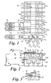
- Fig. 1 is a plan view of an assembly for use in a wall mountable electrical loadcentre with three outgoers attached thereto ;
- Fig. 2 is an end elevational view partly in section, of the assembly of Fig. 1 ;
- Fig. 3 : is an end sectional view, showing an alternative, plug-in connection to the neutral outgoer bus bar of Fig. 2 ;
- Fig. 4 is a plan view of an alternative arrangement to Fig. 1 ;
- Fig. 5 is an end elevational view of the arrangement of Fig. 4 ;
- Fig. 6 is a perspective view of an arrangement of Figs. 1, 2 and 3 and
- Fig. 7 is a perspective view of a further alternative assembly.
-
- Referring now to Figs, 1 and 2 of the drawings there is shown an assembly for use in a wall mountable electrical loadcentre including a mounting means 10 moulded of synthetic plastics material. Mounting means 10 houses three longitudinally extending planar live outgoer bus bars L1, L2 and L3 at a lower level therein and locates a superposed coplanar neutral
outgoer bus bars 11 at the top thereof, with an electrically insulatingcover member 12 located thereover. - Each of the live outgoer bus bars L1, L2 and L3 has an electrically conductive link member 13 (one only shown) attached thereto and a
corresponding connector member 14 is provided for each outgoer position, theconnector member 14 having a portion 14a to be connectable to arespective link member 13 and aportion 14b protruding from mounting means 10 to be connectable to an outgoer, such as acircuit breaker 15. A slidably mounted member 16, formed of electrically insulting material, carries an electrically conductive inverted "T" shapedbidding member 17 and is formed with a manually actuable member orbutton 18. Member 16 is slidable from an "off" position, as shown at the left of Fig. 2, wherebridging member 17 is located onlink member 13 spaced fromconnector portion 14b, to an "on" position, as shown at the right of Fig. 2 wherebridging member 17 spans and connectslink member 13 and hence bus bar L2 to connector portion 14a to enable an outgoer to be supplied fromconnector portion 14b. - The forgoing describes normal "on", "off" connection of an
outgoer 15 to one of the live outgoer bus bars L1, L2 and L3. When anoutgoer 15 is to be connected to the neutraloutgoer bus bar 11 an add-onbar 19 is provided which is attached to neutraloutgoer bus bar 11 by ascrew 20 and extended over the top and down the side of mounting means 10 to engage inoutgoer 15. The add-onbar 19 is formed with an aperture which locates over manuallyactuable member 18 to lock it in its "off" position to prevent a short circuit between the neutraloutgoer bus bar 11 and one of the live outgoer bus bars L1, L2 or L3. Acover member 21 is located over the add-onbar 19. - Figs. 3 and 6 show a modified arrangement of the Figs 1 and 2 assembly were the neutral
outgoer bus bar 11 is of channel transverse cross section with anaperture 11a formed in the walls thereof at each outgoer position. The add-onbar 19 is formed with a sprung prongedend 19a for locating and engaging in the aperture inbus bar 11. - Referring now to Figs. 4 and 5 the mounting means 10 is formed with outwardly extending location ribs or
fins 22 for location with the slotted cover members ofcircuit breakers 15 to be located thereon. With this arrangement each of the live outgoer bus bars L1. L2 and L3 carry connector means 23 (one only shown) for engagement by aclip connector adapter 24. - Our copending United Kingdom patent application n° 9512220.6 (publication n° 2,301,940) shows the detail of such an adapter. When it is required to provide connection from neutral
outgoer bus bar 11 to outgoer 15 the add-onbar 19 is utilised to replace theclip connector adapter 24. - Fig. 7 shows a further alternative arrangement in which the neutral
outgoer bus bar 11 is formed with twoapertures 25 located adjacent each outgoer position, which are engageable by modifiedclip connector adapters 26 and which replaceadapters 24. A cover member (not shown) would be located overbus bar 11 and over eachadapter 26.
Claims (12)
- An electrical load centre bus bars mounting assembly, the load centre being mountable in a wall, the assembly including mounting means (10) locating a plurality of longitudinally extending planar live outgoer bus bars (L1,L2,L3) juxtaposed in a single plane, a longitudinally extending planar neutral outgoer bus bar (11) being located in a superposed plane spaced from said live outgoer bus bars (L1,L2,L3), the assembly being formed for allowing a circuit breaker (15) or other outgoer to be connected to at least any preselected one of said live or neutral outgoer bus bars (L1,L2,L3,11) at any one of a plurality of outgoer positions spaced along the length of said bus bars, at least one add-on bar (19) being provided to connect the neutral outgoer bus bar (11) to a circuit breaker (15) at the respective outgoer position.
- An assembly as claimed in claim 1, wherein the mounting means (10) is moulded of synthetic plastics material.
- An assembly as claimed in claim 2, wherein the mounting means (10) is formed to mount a circuit breaker (15) at each outgoer position along at least one side thereof.
- A assembly as claimed in claim 2 or 3, wherein the mounting means (10) is formed with outwardly extending location ribs or fins (22) for location with slotted covers members of circuit breakers (15) to be located therewith, in use.
- An assembly as claimed in any preceding claim, wherein the neutral outgoer bus bar (11) is located above the live outgoer bus bars (L1,L2,L3) and an electrically insulating cover member is located over the neutral outgoer bus bar (11).
- An assembly as claimed in any preceding claim, wherein the mounting means (10) locates a respective slidable switching link member (13) for each outgoer position for selectively connecting one of the live outgoer bus bars (L1,L2,L3) to a connector member (14) for locating in a circuit breaker (15) and at least one add-on bar (19) located to connect the neutral outgoer bus bar (11) to a circuit breaker (15) at the respective outgoer position, such add-on bar(s) (19) being formed to prevent the slidable switching link member (17) from being actuated to provide a connection from a live outgoer bus bar (L1,L2,L3) to its respective connector member (14).
- An assembly as claimed in claim 6, wherein each slidable switching link member (17) includes an upwardly depending manually actuable member (18) and each add-on bar (19) includes an aperture for surrounding the manually actuable member (18) to locate it in a non-connecting position with regard to its respective live outgoer bus bar (L1,L2,L3).
- An assembly as claimed in claim 6 or 7, wherein each add-on bar has (19) an electrically insulating cover member located there over.
- An assembly as claimed in claim 6, 7 or 8, wherein each add-on bar (19) is attached to the neutral outgoer bus bar (11) by a respective screw (20).
- An assembly as claimed in claim 6, 7 or 8, wherein each add-on bar (19) is formed to plug into the neutral outgoer bus bar (11).
- An assembly as claimed in any one of claims 1 to 5 inclusive wherein the live outgoer bus bars (L1,L2,L3) carry connector means (23) for connection with a clip connector adapter (24) attached to an outgoer device (15) and at least one add-on bar (19) attached to the neutral outgoer bus bar (11) located to be connectable directly to an outgoer device (19) as an alternative to the clip connector adapter (24).
- An assembly as claimed in any one of claims 1 to 5 inclusive, wherein the neutral outgoer bus bar (11) is formed with at least one aperture for each outgoer position for receiving a clip connector adapter (24) of an outgoer device (15) to provide electrical connection thereto.
Applications Claiming Priority (2)
| Application Number | Priority Date | Filing Date | Title |
|---|---|---|---|
| GB9717186A GB2328317B (en) | 1997-08-13 | 1997-08-13 | Improvements in and relating to electrical distribution equipment |
| GB9717186 | 1997-08-13 |
Publications (2)
| Publication Number | Publication Date |
|---|---|
| EP0897207A1 EP0897207A1 (en) | 1999-02-17 |
| EP0897207B1 true EP0897207B1 (en) | 2002-09-25 |
Family
ID=10817446
Family Applications (1)
| Application Number | Title | Priority Date | Filing Date |
|---|---|---|---|
| EP98410089A Expired - Lifetime EP0897207B1 (en) | 1997-08-13 | 1998-08-07 | Improvements in and relating to electrical distribution equipment |
Country Status (7)
| Country | Link |
|---|---|
| EP (1) | EP0897207B1 (en) |
| AU (1) | AU743166B2 (en) |
| DE (1) | DE69808206T2 (en) |
| ES (1) | ES2183306T3 (en) |
| GB (1) | GB2328317B (en) |
| NZ (1) | NZ331394A (en) |
| SA (1) | SA98190445B1 (en) |
Cited By (1)
| Publication number | Priority date | Publication date | Assignee | Title |
|---|---|---|---|---|
| US10218159B2 (en) | 2017-05-10 | 2019-02-26 | Abb Schweiz Ag | Electrical distribution system including neutral connection device and methods of assembling same |
Family Cites Families (5)
| Publication number | Priority date | Publication date | Assignee | Title |
|---|---|---|---|---|
| GB696341A (en) * | 1950-09-14 | 1953-08-26 | Vickers Electrical Co Ltd | Improvements in electrical distribution boards |
| US3097326A (en) * | 1958-11-12 | 1963-07-09 | Fed Pacific Electric Co | Circuit breaker panelboards |
| FR2646568A1 (en) * | 1989-04-26 | 1990-11-02 | Merlin Gerin | Electrical distribution panel equipped with isolators |
| FR2735290B1 (en) * | 1995-06-07 | 1997-07-18 | Schneider Electric Sa | ASSEMBLY AND ELECTRICAL CONNECTION DEVICE FOR MODULAR APPLIANCES SUCH AS CIRCUIT BREAKERS OR SIMILAR |
| AU1238797A (en) * | 1996-01-31 | 1997-08-07 | Schneider Electric Sa | Improvements in and relating to electrical distribution equipment |
-
1997
- 1997-08-13 GB GB9717186A patent/GB2328317B/en not_active Expired - Lifetime
-
1998
- 1998-08-07 DE DE69808206T patent/DE69808206T2/en not_active Expired - Lifetime
- 1998-08-07 EP EP98410089A patent/EP0897207B1/en not_active Expired - Lifetime
- 1998-08-07 ES ES98410089T patent/ES2183306T3/en not_active Expired - Lifetime
- 1998-08-12 AU AU79960/98A patent/AU743166B2/en not_active Ceased
- 1998-08-12 NZ NZ331394A patent/NZ331394A/en not_active IP Right Cessation
- 1998-08-25 SA SA98190445A patent/SA98190445B1/en unknown
Cited By (1)
| Publication number | Priority date | Publication date | Assignee | Title |
|---|---|---|---|---|
| US10218159B2 (en) | 2017-05-10 | 2019-02-26 | Abb Schweiz Ag | Electrical distribution system including neutral connection device and methods of assembling same |
Also Published As
| Publication number | Publication date |
|---|---|
| GB2328317B (en) | 2001-09-12 |
| AU7996098A (en) | 1999-02-25 |
| AU743166B2 (en) | 2002-01-17 |
| GB9717186D0 (en) | 1997-10-22 |
| ES2183306T3 (en) | 2003-03-16 |
| DE69808206D1 (en) | 2002-10-31 |
| NZ331394A (en) | 1999-08-30 |
| SA98190445B1 (en) | 2006-10-04 |
| EP0897207A1 (en) | 1999-02-17 |
| GB2328317A (en) | 1999-02-17 |
| DE69808206T2 (en) | 2003-05-15 |
Similar Documents
| Publication | Publication Date | Title |
|---|---|---|
| US4931898A (en) | Loadcenter busbar retention | |
| US5094626A (en) | Set of assembly elements intended to facilitate concurrent electrical connection of a plurality of modular automatic circuit breakers | |
| US5726852A (en) | Modular DC distribution unit and system | |
| US4785378A (en) | Loop-feed wiring arrangement for electric circuit breakers and switches | |
| AU672639B2 (en) | Protective cover for electrical bus bars and method of using same | |
| US4962443A (en) | Improved residential loadcenter | |
| US11837829B2 (en) | Adapter device for power busbar systems | |
| US20240153726A1 (en) | Snap fit circuit breaker and load center system | |
| EP0788205A2 (en) | Improvements in and relating to electrical distribution equipment | |
| US4931902A (en) | Bushbar barrier protective members | |
| US4931903A (en) | Loadcenter mounting rail adapter | |
| US6307456B1 (en) | Light industrial circuit breaker terminal cover | |
| EP2124303A1 (en) | Adapter, adapter in combination with an MCCB for a low voltage switchboard, use of such adapter and an electric switchboard comprising such adapter | |
| EP0897207B1 (en) | Improvements in and relating to electrical distribution equipment | |
| GB2310768A (en) | Distribution equipment for a wall mountable consumer unit | |
| US20070279166A1 (en) | Replacement circuit breaker for electric panelboards | |
| FI88557C (en) | Telecommunication installation box | |
| EP2020669B1 (en) | Electrical connection auxiliary module for circuit breakers. | |
| PL179204B1 (en) | Apparatus for connecting an electric wiring system equipment | |
| JP4278210B2 (en) | Distribution board ground relay terminal | |
| GB2131632A (en) | Electric plugs | |
| EP0526256B1 (en) | Connectors | |
| JP2005110433A (en) | Distribution board | |
| GB2282702A (en) | Adaptor for an electrical consumer unit | |
| JPH07123537A (en) | Distribution board |
Legal Events
| Date | Code | Title | Description |
|---|---|---|---|
| PUAI | Public reference made under article 153(3) epc to a published international application that has entered the european phase |
Free format text: ORIGINAL CODE: 0009012 |
|
| AK | Designated contracting states |
Kind code of ref document: A1 Designated state(s): DE ES FR IT |
|
| AX | Request for extension of the european patent |
Free format text: AL;LT;LV;MK;RO;SI |
|
| RAP1 | Party data changed (applicant data changed or rights of an application transferred) |
Owner name: SCHNEIDER ELECTRIC INDUSTRIES SA |
|
| 17P | Request for examination filed |
Effective date: 19990731 |
|
| AKX | Designation fees paid |
Free format text: DE ES FR IT |
|
| RAP1 | Party data changed (applicant data changed or rights of an application transferred) |
Owner name: SCHNEIDER ELECTRIC INDUSTRIES SA |
|
| GRAG | Despatch of communication of intention to grant |
Free format text: ORIGINAL CODE: EPIDOS AGRA |
|
| 17Q | First examination report despatched |
Effective date: 20020207 |
|
| GRAG | Despatch of communication of intention to grant |
Free format text: ORIGINAL CODE: EPIDOS AGRA |
|
| GRAH | Despatch of communication of intention to grant a patent |
Free format text: ORIGINAL CODE: EPIDOS IGRA |
|
| GRAH | Despatch of communication of intention to grant a patent |
Free format text: ORIGINAL CODE: EPIDOS IGRA |
|
| GRAA | (expected) grant |
Free format text: ORIGINAL CODE: 0009210 |
|
| RAP1 | Party data changed (applicant data changed or rights of an application transferred) |
Owner name: SCHNEIDER ELECTRIC INDUSTRIES SAS |
|
| AK | Designated contracting states |
Kind code of ref document: B1 Designated state(s): DE ES FR IT |
|
| REF | Corresponds to: |
Ref document number: 69808206 Country of ref document: DE Date of ref document: 20021031 |
|
| ET | Fr: translation filed | ||
| REG | Reference to a national code |
Ref country code: ES Ref legal event code: FG2A Ref document number: 2183306 Country of ref document: ES Kind code of ref document: T3 |
|
| PLBE | No opposition filed within time limit |
Free format text: ORIGINAL CODE: 0009261 |
|
| STAA | Information on the status of an ep patent application or granted ep patent |
Free format text: STATUS: NO OPPOSITION FILED WITHIN TIME LIMIT |
|
| PG25 | Lapsed in a contracting state [announced via postgrant information from national office to epo] |
Ref country code: ES Free format text: LAPSE BECAUSE OF NON-PAYMENT OF DUE FEES Effective date: 20030808 |
|
| 26N | No opposition filed |
Effective date: 20030626 |
|
| REG | Reference to a national code |
Ref country code: ES Ref legal event code: FD2A Effective date: 20030808 |
|
| PG25 | Lapsed in a contracting state [announced via postgrant information from national office to epo] |
Ref country code: IT Free format text: LAPSE BECAUSE OF NON-PAYMENT OF DUE FEES Effective date: 20050807 |
|
| REG | Reference to a national code |
Ref country code: DE Ref legal event code: R084 Ref document number: 69808206 Country of ref document: DE Effective date: 20111228 |
|
| REG | Reference to a national code |
Ref country code: FR Ref legal event code: PLFP Year of fee payment: 18 |
|
| PGFP | Annual fee paid to national office [announced via postgrant information from national office to epo] |
Ref country code: FR Payment date: 20150624 Year of fee payment: 18 |
|
| PGFP | Annual fee paid to national office [announced via postgrant information from national office to epo] |
Ref country code: DE Payment date: 20150708 Year of fee payment: 18 |
|
| REG | Reference to a national code |
Ref country code: DE Ref legal event code: R119 Ref document number: 69808206 Country of ref document: DE |
|
| REG | Reference to a national code |
Ref country code: FR Ref legal event code: ST Effective date: 20170428 |
|
| PG25 | Lapsed in a contracting state [announced via postgrant information from national office to epo] |
Ref country code: DE Free format text: LAPSE BECAUSE OF NON-PAYMENT OF DUE FEES Effective date: 20170301 Ref country code: FR Free format text: LAPSE BECAUSE OF NON-PAYMENT OF DUE FEES Effective date: 20160831 |