EP0897126A2 - Remote approval of lenticular images - Google Patents
Remote approval of lenticular images Download PDFInfo
- Publication number
- EP0897126A2 EP0897126A2 EP98202585A EP98202585A EP0897126A2 EP 0897126 A2 EP0897126 A2 EP 0897126A2 EP 98202585 A EP98202585 A EP 98202585A EP 98202585 A EP98202585 A EP 98202585A EP 0897126 A2 EP0897126 A2 EP 0897126A2
- Authority
- EP
- European Patent Office
- Prior art keywords
- image
- images
- lenticular
- hub station
- lenticular image
- Prior art date
- Legal status (The legal status is an assumption and is not a legal conclusion. Google has not performed a legal analysis and makes no representation as to the accuracy of the status listed.)
- Withdrawn
Links
Images


Classifications
-
- G—PHYSICS
- G02—OPTICS
- G02B—OPTICAL ELEMENTS, SYSTEMS OR APPARATUS
- G02B30/00—Optical systems or apparatus for producing three-dimensional [3D] effects, e.g. stereoscopic images
- G02B30/20—Optical systems or apparatus for producing three-dimensional [3D] effects, e.g. stereoscopic images by providing first and second parallax images to an observer's left and right eyes
- G02B30/26—Optical systems or apparatus for producing three-dimensional [3D] effects, e.g. stereoscopic images by providing first and second parallax images to an observer's left and right eyes of the autostereoscopic type
- G02B30/27—Optical systems or apparatus for producing three-dimensional [3D] effects, e.g. stereoscopic images by providing first and second parallax images to an observer's left and right eyes of the autostereoscopic type involving lenticular arrays
-
- H—ELECTRICITY
- H04—ELECTRIC COMMUNICATION TECHNIQUE
- H04N—PICTORIAL COMMUNICATION, e.g. TELEVISION
- H04N1/00—Scanning, transmission or reproduction of documents or the like, e.g. facsimile transmission; Details thereof
- H04N1/00127—Connection or combination of a still picture apparatus with another apparatus, e.g. for storage, processing or transmission of still picture signals or of information associated with a still picture
- H04N1/00132—Connection or combination of a still picture apparatus with another apparatus, e.g. for storage, processing or transmission of still picture signals or of information associated with a still picture in a digital photofinishing system, i.e. a system where digital photographic images undergo typical photofinishing processing, e.g. printing ordering
- H04N1/00185—Image output
- H04N1/00201—Creation of a lenticular or stereo hardcopy image
-
- H—ELECTRICITY
- H04—ELECTRIC COMMUNICATION TECHNIQUE
- H04N—PICTORIAL COMMUNICATION, e.g. TELEVISION
- H04N13/00—Stereoscopic video systems; Multi-view video systems; Details thereof
- H04N13/10—Processing, recording or transmission of stereoscopic or multi-view image signals
- H04N13/194—Transmission of image signals
-
- H—ELECTRICITY
- H04—ELECTRIC COMMUNICATION TECHNIQUE
- H04N—PICTORIAL COMMUNICATION, e.g. TELEVISION
- H04N13/00—Stereoscopic video systems; Multi-view video systems; Details thereof
- H04N13/20—Image signal generators
- H04N13/275—Image signal generators from 3D object models, e.g. computer-generated stereoscopic image signals
-
- H—ELECTRICITY
- H04—ELECTRIC COMMUNICATION TECHNIQUE
- H04N—PICTORIAL COMMUNICATION, e.g. TELEVISION
- H04N13/00—Stereoscopic video systems; Multi-view video systems; Details thereof
- H04N13/30—Image reproducers
- H04N13/302—Image reproducers for viewing without the aid of special glasses, i.e. using autostereoscopic displays
- H04N13/305—Image reproducers for viewing without the aid of special glasses, i.e. using autostereoscopic displays using lenticular lenses, e.g. arrangements of cylindrical lenses
-
- H—ELECTRICITY
- H04—ELECTRIC COMMUNICATION TECHNIQUE
- H04N—PICTORIAL COMMUNICATION, e.g. TELEVISION
- H04N13/00—Stereoscopic video systems; Multi-view video systems; Details thereof
- H04N13/30—Image reproducers
- H04N13/327—Calibration thereof
-
- H—ELECTRICITY
- H04—ELECTRIC COMMUNICATION TECHNIQUE
- H04N—PICTORIAL COMMUNICATION, e.g. TELEVISION
- H04N13/00—Stereoscopic video systems; Multi-view video systems; Details thereof
- H04N13/30—Image reproducers
- H04N13/332—Displays for viewing with the aid of special glasses or head-mounted displays [HMD]
- H04N13/341—Displays for viewing with the aid of special glasses or head-mounted displays [HMD] using temporal multiplexing
-
- H—ELECTRICITY
- H04—ELECTRIC COMMUNICATION TECHNIQUE
- H04N—PICTORIAL COMMUNICATION, e.g. TELEVISION
- H04N13/00—Stereoscopic video systems; Multi-view video systems; Details thereof
- H04N13/30—Image reproducers
- H04N13/332—Displays for viewing with the aid of special glasses or head-mounted displays [HMD]
- H04N13/344—Displays for viewing with the aid of special glasses or head-mounted displays [HMD] with head-mounted left-right displays
-
- H—ELECTRICITY
- H04—ELECTRIC COMMUNICATION TECHNIQUE
- H04N—PICTORIAL COMMUNICATION, e.g. TELEVISION
- H04N13/00—Stereoscopic video systems; Multi-view video systems; Details thereof
- H04N13/30—Image reproducers
- H04N13/349—Multi-view displays for displaying three or more geometrical viewpoints without viewer tracking
-
- H—ELECTRICITY
- H04—ELECTRIC COMMUNICATION TECHNIQUE
- H04N—PICTORIAL COMMUNICATION, e.g. TELEVISION
- H04N13/00—Stereoscopic video systems; Multi-view video systems; Details thereof
- H04N13/30—Image reproducers
- H04N13/366—Image reproducers using viewer tracking
-
- H—ELECTRICITY
- H04—ELECTRIC COMMUNICATION TECHNIQUE
- H04N—PICTORIAL COMMUNICATION, e.g. TELEVISION
- H04N13/00—Stereoscopic video systems; Multi-view video systems; Details thereof
- H04N13/30—Image reproducers
- H04N13/398—Synchronisation thereof; Control thereof
-
- H—ELECTRICITY
- H04—ELECTRIC COMMUNICATION TECHNIQUE
- H04N—PICTORIAL COMMUNICATION, e.g. TELEVISION
- H04N13/00—Stereoscopic video systems; Multi-view video systems; Details thereof
- H04N13/10—Processing, recording or transmission of stereoscopic or multi-view image signals
-
- H—ELECTRICITY
- H04—ELECTRIC COMMUNICATION TECHNIQUE
- H04N—PICTORIAL COMMUNICATION, e.g. TELEVISION
- H04N13/00—Stereoscopic video systems; Multi-view video systems; Details thereof
- H04N13/10—Processing, recording or transmission of stereoscopic or multi-view image signals
- H04N13/106—Processing image signals
- H04N13/161—Encoding, multiplexing or demultiplexing different image signal components
-
- H—ELECTRICITY
- H04—ELECTRIC COMMUNICATION TECHNIQUE
- H04N—PICTORIAL COMMUNICATION, e.g. TELEVISION
- H04N13/00—Stereoscopic video systems; Multi-view video systems; Details thereof
- H04N13/10—Processing, recording or transmission of stereoscopic or multi-view image signals
- H04N13/189—Recording image signals; Reproducing recorded image signals
-
- H—ELECTRICITY
- H04—ELECTRIC COMMUNICATION TECHNIQUE
- H04N—PICTORIAL COMMUNICATION, e.g. TELEVISION
- H04N13/00—Stereoscopic video systems; Multi-view video systems; Details thereof
- H04N13/20—Image signal generators
- H04N13/286—Image signal generators having separate monoscopic and stereoscopic modes
-
- H—ELECTRICITY
- H04—ELECTRIC COMMUNICATION TECHNIQUE
- H04N—PICTORIAL COMMUNICATION, e.g. TELEVISION
- H04N13/00—Stereoscopic video systems; Multi-view video systems; Details thereof
- H04N13/30—Image reproducers
- H04N13/302—Image reproducers for viewing without the aid of special glasses, i.e. using autostereoscopic displays
- H04N13/307—Image reproducers for viewing without the aid of special glasses, i.e. using autostereoscopic displays using fly-eye lenses, e.g. arrangements of circular lenses
-
- H—ELECTRICITY
- H04—ELECTRIC COMMUNICATION TECHNIQUE
- H04N—PICTORIAL COMMUNICATION, e.g. TELEVISION
- H04N13/00—Stereoscopic video systems; Multi-view video systems; Details thereof
- H04N13/30—Image reproducers
- H04N13/302—Image reproducers for viewing without the aid of special glasses, i.e. using autostereoscopic displays
- H04N13/31—Image reproducers for viewing without the aid of special glasses, i.e. using autostereoscopic displays using parallax barriers
-
- H—ELECTRICITY
- H04—ELECTRIC COMMUNICATION TECHNIQUE
- H04N—PICTORIAL COMMUNICATION, e.g. TELEVISION
- H04N13/00—Stereoscopic video systems; Multi-view video systems; Details thereof
- H04N13/30—Image reproducers
- H04N13/324—Colour aspects
-
- H—ELECTRICITY
- H04—ELECTRIC COMMUNICATION TECHNIQUE
- H04N—PICTORIAL COMMUNICATION, e.g. TELEVISION
- H04N19/00—Methods or arrangements for coding, decoding, compressing or decompressing digital video signals
- H04N19/50—Methods or arrangements for coding, decoding, compressing or decompressing digital video signals using predictive coding
- H04N19/597—Methods or arrangements for coding, decoding, compressing or decompressing digital video signals using predictive coding specially adapted for multi-view video sequence encoding
Abstract
Description
- This invention relates to the field of integral imaging, and lenticular imaging in particular.
- Integral image elements which use a lenticular lens sheet or a fly's eye lens sheet, and a three-dimensional integral image aligned with the sheet, so that a user can view the three-dimensional image without any special glasses or other equipment, are known. Such imaging elements and their construction, are described in "Three-Dimensional Imaging Techniques" by Takanori Okoshi, Academic Press, Inc., New York, 1976. Integral image elements having a lenticular lens sheet (that is, a sheet with a plurality of adjacent, parallel, elongated, and partially cylindrical lenses) are also described in the following Unites States patents: US 5,391,254; US 5,424,533; US 5,241,608; US 5,455,689; US 5,276,478; US 5,391,254; US 5,424,533 and others; as well as allowed US patent application Serial Number 07/931,744. Use of barrier viewing sheets having alternating opaque and transparent lines, instead of a lenticular lens sheet, is also well known.
- Integral image elements with lenticular lens sheets use interlaced vertical image slices which, in the case of a three-dimensional integral image, are aligned with the lenticules so that a three-dimensional image is viewable when the lenticules are vertically oriented with respect to a viewer's eyes. Similar integral image elements, such as described in US 3,268,238 and US 3,538,632, can be used to convey a number of individual two-dimensional scenes (such as unrelated scenes or a sequence of scenes depicting motion) rather than one or more three-dimensional images. Such elements then, when tilted through a range of angles with respect to a viewer's eyes (by moving the element and/or the viewer's eyes), can display different images (whether different perspectives of the same scene) and/or unrelated images, and/or a sequence of images depicting a motion sequence of events. Alternatively, a lenticular image and lens can be slid (either manually or my a motorized arrangement) with respect to one another in a direction orthogonal to the lenticule direction. This can provide for convenient display of a motion or other lenticular image, without changing the angle between the viewer and the lenticular image element. With improvements in technology, the effects obtained can be startling.
- Integral image elements using reflective layers behind the integral image to enhance viewing of the integral image by reflected light, are also described in US 3,751,258, US 2,500,511, US 2,039,648, US 1,918,705 and GB 492,186.
- In a typical method of assembling a lenticular type of integral image element, an original negative is exposed from stored digitized data of a composite lenticular image on a film writer. A suitable film writer is the Symbolic Sciences International Fire 1000 and the LVT Model 1620B, available from Light Valve Technology, a subsidiary of Eastman Kodak Company, Rochester, New York. A suitable negative exposure technique is disclosed in U.S. Patent 5,276,478. After photographic processing, the negative is printed, typically by a projection enlarger, onto a suitable film- or paper-based photographic print stock. After processing, the lenticular composite print is coated with adhesive, aligned with a lenticular lens sheet, and pressed against the lens sheet to permanently adhere to it in proper registration with the printed lenticular composite image. However, it is also known to write the lenticular image directly onto a back side of a lenticular lens sheet which is coated with a suitable receiving layer, such as disclosed in US 5,349,419 and US 5,279,912. Furthermore, such "writing" of the lenticular image can be temporary, as in a display produced on a CRT or Liquid Crystal Display ("LCD") screen immediately adjacent the back side.
- In forming a lenticular image, the various images from which a lenticular image is formed are decomposed into strips or lines (which may be one or more pixels in width) and these are interleaved and aligned behind a corresponding lenticule at its focal point, in a known manner. Such interleaving is, for example, described in US 4,506,296, US 5,278,608, US 5,276,478, US 5,455,689, and US 3,534,164. This process is computationally intensive and requires considerable time for lenticular images of high resolution. Furthermore, since different lenticular lens sheets have different physical parameters, such as lenticular pitch, the required calculations can change for a lenticular image of given content for different lenticular lens sheets.
- Often however, in the preparation of a desired lenticular image, the customer for the final lenticular image is remote from a lenticular image production facility which has lenticular lens sheets of different parameters, the required high computer power, and the necessary high resolution printers, and also alignment devices (which may or may not be part of the printer). Further, creative personnel may be present at such sites to aid in subjective judgements as to variations in lenticular image characteristics in order to obtain a final lenticular element of good quality. However, in most cases a customer's approval is necessary before the job can proceed to its next step. Conventionally, this required actually producing a rough lenticular image element based on oral discussions with the customer. This would then be delivered to the customer for review. Based on customer input, one or more such rough lenticular image elements might be required. Such a procedure is exceedingly costly, time consuming, and tedious.
- It would be desirable then, to provide a means by which lenticular image elements can be created at a central facility, but which still allow a remote customer to provide approval prior to production of the final lenticular image, without having go through the foregoing tedious procedure.
- The present invention recognizes that remote approval of a lenticular image can be obtained using a communication system between a computer at a central integral image manufacturing facility and a remote terminal. The present invention further realizes that integral images, unlike ordinary images, cannot actually be viewed on a conventional two-dimensional computer display. That is, a conventional two-dimensional display cannot display integral images in the manner they appear through an actual integral lens sheet. Furthermore, the present invention also realizes that transferring the large amounts of data representing the many conventional images from which an integral image is formed, is not desirable due to current bandwidth problems on many lower cost communications networks (such as a telephone network).
- The present invention provides then, in one aspect, a method for remote approval of lenticular images, comprising:
- a) at a centralized hub station, receiving a series of images;
- b) viewing, at a terminal remote from the centralized hub station, a simulated lenticular image using at least some images of the series displayed to simulate viewing an actual lenticular image formed from the images of the series;
- c) transmitting an approval from the remote terminal to the centralized hub station, for a plurality of the images of the series to be printed as the actual lenticular image;
- d) at the hub station, printing the actual lenticular image based on the approval.
-
- In another second aspect, the present invention provides a method for remote approval of lenticular images between a centralized hub station and a terminal remote from the hub, comprising:
- a) viewing, at the remote terminal, a simulated lenticular image using a series of images displayed to simulate viewing an actual lenticular image formed from images of the series, which simulated image is based on at least one physical parameter of a lenticular lens sheet;
- b) transmitting the at least one lens sheet parameter between the hub station and remote terminal;
- c) transmitting an approval of the actual lenticular image from the remote terminal to the hub station; and
- d) at the hub station, printing the actual lenticular image and aligning it with a lenticular lens sheet having the at least one lens sheet parameter.
-
- The present invention further provides an apparatus for printing lenticular images with remote approval, comprising:
- a) a centralized hub station having:
- a first communication means for allowing the centralized hub station to communicate with a terminal remote from the hub station;
- a printer to print a lenticular image based on an approval communicated from a remote hub station;
- b) a terminal remote from the hub station having:
- a display means for viewing a simulated lenticular image which uses a plurality of images displayed to simulate viewing an actual lenticular image formed from images of a series;
- second communication means for communicating with the centralized hub station, including transmitting an approval for a plurality of the image series to be printed as a lenticular image.
-
- The invention of the present invention allows an individual remote from a central site which may make the lenticular image, to obtain a relatively realistic representation of the appearance of a desired actual lenticular image prior to printing the image at the central site, using readily available computer equipment. The invention further allows the necessary approval for the actual lenticular image to therefore be obtained without need for manufacturing one or more rough lenticular image elements. Further, the invention can allow for a reduced data volume transmitted between the central location and the remote terminal, versus that required for transmitting all of the images which form the desired actual lenticular image.
-
- FIG. 1 is a perspective view of a typical lenticular image element;
- FIG. 2 is a side view illustrating tilting of a lenticular motion image element to view the images of the motion sequence;
- FIGS. 3-5 are enlarged side views illustrating in detail what a viewer sees through each lenticule during the tilting motion of FIG. 2;
- FIG. 6 is a block diagram illustrating an apparatus of the present invention;
- FIG. 7 illustrates operation of a portion of the apparatus in FIG. 6 in more detail;
- FIG. 8 illustrates display of a simulated lenticular image as a timed sequence of images in an actual lenticular image;
- FIG. 9 is a view, from above, illustrating display of a simulated three-dimensional lenticular image;
- FIG. 10 is a side view illustrating further features for displaying a simulated three-dimensional lenticular image;
- FIG. 11 illustrates an alternative arrangement for displaying a simulated three-dimensional lenticular image;
- FIG. 12 illustrates an apparatus for determining a lenticular lens sheet light intensity distribution, for use in forming a simulated lenticular image, across a series of observed images as a viewer's angle relative to an actual lenticular image is altered;
- FIG. 13 illustrates a typical distribution as measured in the apparatus of FIG. 12;
- FIG. 14 illustrates a typical light distribution across individual lenticules of a lenticular image, for use in forming a simulated lenticular image; and
- FIG. 15 illustrates a simulated motion lenticular image as a sequence of images observed on a display and corresponding motion of the corresponding actual lenticular image.
-
- To facilitate understanding, identical reference numerals have been used, where possible, to designate identical elements that are common to the figures.
- In the present invention, it will be understood that a "set" of images includes one or more images. The images may be of any type, and include any number or all of the images being images of real world scenes or computer generated images generated from still image sequences, depth image sequences, or motion sequences in either film or electronic or other image source. An "image" when used alone, is used to reference a conventional two-dimensional image such as might be observed by the unaided eye on a conventional photograph or printed page, unless the contrary is indicated. While the integral lens sheet used in the present invention could be a fly's eye lens sheet it is more preferably a lenticular lens sheet with lenticules on a front surface, in which case the corresponding image used with the sheet is a lenticular image. Alternatively, the integral lens sheet could have regions of varying indices of refraction through its volume configured in such a way as to provide (in conjunction with the surfaces of the sheet, such as a curved external surface, flat external surface or some other shape) the same optical deflection of light rays as would be provided by a conventional fly's eye or lenticular lens sheet. Also, the back surface of the lens sheet may also be curved so as to either strengthen the lens effect or compensate for the curved focal plane which may be inherent in the lens construction. Consequently, the curvature on the back side may be of such a shape as to match the curvature of the focal plane of the lens. Further, by an "integral" image is referenced an image composed of segments (interleaved lines, in the case of a lenticular image) from at least one complete image (and typically more than one image), which segments are aligned with respective individual lenses so that each of the one or more images is viewable when a user's eyes are at the correct angle relative to the imaging element. An integral lens web may be a continuous web of any integral element lens sheet. A lenticular lens sheet in aspect of the present invention, can be readily replaced with a barrier sheet which is formed of a plurality of elongated, parallel, slits, in a known manner for use with the lenticular images. However, since barrier sheets block much of the light from the lenticular image, viewed image brightness will typically be less than when an equivalent lenticular lens sheet is used.
- It will be appreciated throughout this application, by a "processor" is referenced a suitable signal processor, such as a suitably programmed general purpose digital processor or hard wired equivalent circuitry, or any combination of the two. A "memory" can be any suitable signal storage device, such as a magnetic or optical disk drive or tape, or a solid state memory. As to transmitting or communicating images, this references sending image signals corresponding to images, from one location to another. Thus, reference to images that are to be transmitted implies, unless otherwise indicated, that image signals are being referenced. By "remote" in the present case, is referenced that the two locations of interest are preferably in a different building, or they may be separated by 1 or more, 5 or more, 100 or more, or even 1000 or more, miles.
- As to the receiving medium on which the integral image is written, this can simply be the back side of the integral lens sheet (which in a conventional integral lens sheet is opposite shaped lens surfaces, such as the semi-cylindrical shaped lens surfaces of a lenticular lens sheet). Alternatively, the image receiving medium could be one or more layers coated on the back side, such as a photosensitive layer or layers (which may in particular be any known photographic layer or layers) or a thermal receiver layer, or a suitable substrate which is later attached to an integral lens sheet. Additionally, the image receiving medium on the back side, can be covered with a protective layer either before or after writing the image. In the case of such a protective layer covering before writing the image, the protective layer can be transparent so that writing can be done by a light beam illuminating photosensitive layers on the back side. It will also be appreciated that the methods of the present invention can be applied to integral images (and particularly lenticular images) which can exhibit a wide range of effects including motion, depth, flip (that is, apparently unrelated images), and other lenticular related effects.
- In this application, by a perspective sequence of images is referenced a sequence of images (at least two) in an integral image which are views of a scene taken from different perspectives (that is, from different angular positions) and thereby provide a three-dimensional effect when viewed through the integral lens sheet. The resulting lenticular image may be referred to as a three-dimensional lenticular image. If at least three different perspectives images are used, this can include the ability to at least partially look around an object in the scene. A motion sequence is a sequence of images (such as two, three, four or more images) each image of which has at least one (or most, or all) scene element in common but which changes location, shape or size within the scene in a logical manner through the sequence. Motion image sequences for lenticular images are generally two-dimensional images but can be made from a perspective sequences. By a two-dimensional image is referenced an image which, when aligned and viewed through an integral lens, does not have any viewable depth element (that is, it does not appear three-dimensional and the viewer cannot look around it at all). By a scene element in this regard, is referenced the same view of the same object (which includes the object appearing to be the same size).
- Turning now to the drawings, a typical actual (or real) lenticular image element, as seen on Figure 1, includes a lenticular image 11 containing
sets 14 of interleaved lines related to specific lenticules and positioned for a specific viewing distance (only somesets 14 being shown in Figure 1 for clarity), taken from individual images. Each set 14 contains a line from each image, in a manner well known in the lenticular imaging art. The lenticular image element also includes alenticular lens sheet 12.Lens sheet 12 includes on a front side 12a, plural adjacent and parallelstraight lenticules 13 with their typically convex lens surfaces. Interleaved image 11 is typically positioned adjacent aback side 12b of lens sheet 12 (although it could be spaced therefrom) with each set oflines 14 aligned with acorresponding lenticule 13. Such alignment does not necessarily require that all lines of aset 14 will be directly beneath a corresponding lenticule 13 (although they often will be), since in some cases such as described in US 5,276,478 and 5,278,608, some of the lines of a set may in fact be beneath an adjacent lenticule. Hence, the alignment is an optical alignment with image sets being positioned depending upon the intended viewing distance from the lenticular image. Image 11 when aligned withlens sheet 12, are together sometimes referenced as a lenticular image element. When image 11 andlens sheet 12 are positioned as shown in Figure 1, with the lenticules ofsheet 12 parallel to the plane of a viewer's eyes (sometimes referenced as a user or observer).lens sheet 12 allows the observer to see only one of the images at a time. Note that if the lenticular image element of Figure 1 is rotated 90 degrees from the horizontal position of Figure 1 so that the lenticules are perpendicular to a viewer's eyes, two images can be seen at the same time, thus enabling viewing of a three-dimensional lenticular image in a known manner. With regard to Figure 2 anobserver 24 can see all the images by successively tilting the display through an angle to variousdifferent positions - To form a lenticular image, the various images (that is, conventional images) from which a lenticular image is to be formed, are decomposed into strips or lines (which may be one or more pixels in width). These image strips or lines from the different images are interleaved and aligned behind a corresponding lenticule at its focal point, in a known manner. Such interleaving is, for example, described in US 4,506,296, US 5,278,608, US 5,276,478, US 5,455,689, and US 3,534,164. Thus, as seen on Figure 3 when an
observer 24 is looking through the lenticular array, he or she can see, at a sufficiently large viewing distance, theimage line 42. By seeing simultaneously all the lenticules, one can see simultaneously all the image lines of one image and hence can see observe a complete corresponding image. As shown in Figure 4, as the view angle of theobserver 24 relative to the lenticular image is altered, animage line 43 from another image will be seen by the observer behind the lenticule array (and hence the observer sees a different image). Similarly, as the observer continues to increase their angle away from a line 90° to the lenticular plane about the axis of lenticules 13 (specifically, away from the plane normal to those axes), as shown in FIG. 5, animage line 45 from still another image will be observed (and hence the observer sees still another image). Because the width of each image line is much narrower than the width of the lenticule itself, many image lines can be behind the same lenticule (the number of different image lines corresponding to the number of images that can be seen). The image which is then seen by the observer depends on the view angle of the lenticular image. Thus, as mentioned above, tilting a lenticular image element through a range of angles allows observation of a sequence of motion images, in the case of a lenticular motion image. - Referring now to FIG. 6 in particular, an apparatus and method of the present invention will be described. In the apparatus of FIG. 6 a
centralized hub station 50 can communicate with any one ofremote terminals 72 through a network in the form of astandard telephone network 70. In the following discussion, it will be assumed thathub station 50 is communicating with a specific one ofremote terminals 72 at which the consumer is located. However, simultaneous communication with other consumers at other of the remote terminals is, or course, possible. -
Centralized hub station 50 receives from a customer, a physical media in the form offilm 62 orvideotape 64, carrying a plurality of images to be used for forming a corresponding actual lenticular image. Alternatively,hub station 50 can receive images as data such as from adigital camera 66 communicating withhub station 50. Aconverter 56 performs any necessary conversion of the images received to generate images in a digital format suitable for handling by aprocessor 54 ofhub station 50, as well as byremote terminals 72. Such conversion may include chemical processing offilm 62 where such film is undeveloped, or converting the analog images on adeveloped film 62 or on an analog videotape, to digital image signals. -
Processor 54 receives the images from converter 56 (which images are now in the form of digital signals) and stores them in amemory 55. A number of alternative procedures may then take place. In one procedure,processor 54 communicates the individual images through a communications means 62 to one of theremote terminals 72 at which the customer is present (the customer previously having connected into centralized hub station 50), for storage in amemory 83. In addition, physical parameters oflenticular lens sheets 12, which are available athub station 50, may also be transmitted to theremote terminal 72 through the network. Such physical parameters include information on lenticular pitch, lens sheet sizes, number of views or frames per lenticule, data from which can be determined the expected light distribution from observed images viewed through a lenticular lens sheet aligned with a desired actual lenticular image as the angle of viewing about the axis of the lenticules is altered, or other optical parameters of thelenticular lens sheets 12 available athub station 50. A communication means 80 receives such signals and passes them along toprocessor 82. -
Processor 82 can then allow the consumer, through user interface 103 (which may includes a keyboard, mouse, voice recognition means, and the like) to select which of the images received he would like to have incorporated into a lenticular image (such as a motion lenticular image or three-dimensional lenticular image). With this information and the received data on available lenticular lens sheet parameters,processor 82 can then form a simulated lenticular image using the images of the received series which were selected by the consumer. Various options for providing the simulated image to adisplay 102 are discussed in more detail below. When the consumer is satisfied with a simulated lenticular image appearing ondisplay 102, they can then indicate their approval to produce the corresponding actual lenticular image, throughinterface 103 which is transmitted tohub station 50. The approval may take the form of transmitting the approved interleaved image itself, in whichcase processor 82 does the necessary interleaving of the images selected to form the lenticular image. To reduce the amount of data required to be transmitted though, the approval may just be an indication of the characteristics of the desired actual lenticular image, just as the number of images, an identification of the actual images selected, the pitch (that is, the width) of the image lines and their positioning relative to correspondinglenticules 13. In any either, the approval may further include an indication of the particular lenticular lens sheet (that is, the one with the desired parameters) with which the actual lenticular image is to be aligned. - The consumer may optionally wish to add to the viewed images of a simulated lenticular image, one or more images which they have already acquired in a suitable format at
remote terminal 72. Such images can added to an interleaved lenticular image atremote terminal 72 if this is to be transmitted as the approval, or can be transmitted in their original form for subsequent interleaving athub station 50 in the case where the transmitted approval fromremote terminal 72 is only an indication of the actual lenticular image characteristics. The added images themselves can be any type of image, including images of the real world and/or computer generated images. For example, the added image may be interpolated from one or more images of the series originally obtained fromfilm 62,videotape 64 orcamera 66, and may be text or titles, template images, special effects (including fade effects between frames). - The approval is received by
processor 54. If the approval is in the form of the actual lenticular image itself, the received lenticular image may be sent directly to aprinter 58. If the approval is in the form of the actual lenticular image data (which inherently includes lenticular image characteristics), thenprocessor 54 interleaves lines from the individual images stored inmemory 55 in accordance with those characteristics, then sends the resulting desired actual lenticular image toprinter 58. Transmitting only the lenticular image characteristics not only allows reduction in transmitted data volume (and hence time savings) but also allows the more computationally intensive interleaving process to be performed at thecentralized hub station 50, which is likely to have higher data processing capabilities than any ofremote terminals 72. -
Printer 58 may be any suitable hght resolution printer, using an inkjet, thermal, electrophotographic or optical technology. Printer 58 (or other optical technology) may print the lenticular image on a suitable substrate which is then afterward either manually aligned with thelenticular lens sheet 12 having the parameters selected by the consumer (and which were used to generate the simulated lenticular image at remote terminal 72), or aligned using any suitable alignment apparatus 60 (such as described in US 5,479,270. Alternatively,printer 58 can align the actual lenticular image with thelens sheet 12 during printing of the image by printing directly onto the back side of lens sheet 12 (that is, on the flat side opposite the side of the lenticules), including printing onto a suitable receiving medium, such as a photosensitive layer on the back side. For example,printer 58 could be a laser or other modulated light beam printer which prints the lenticular image, line by line, onto a photographic layer on the back side oflens sheet 12. In another alternative, the images can be printed on one side of a planar substrate, then the lenticules formed on the other side after printing of the image. - In modifications of the above procedure, the physical media such as a
developed film 62, carrying the images or the images in electronic form, can alternatively first be received atremote terminal 72. In this case,remote terminal 72 may have to be provided with a converter 56 (e.g. optical scanner). In such case, data flow can be further reduced by eliminating the need forcentralized hub station 50 to transmit the individual images toremote terminal 72, it being only necessary thatremote terminal 72 transmit an approval in the form of a lenticular image. In a case where the individual images are previously available at both remote terminal andhub station 50, data flow can be further reduced by remote terminal transmitting only the characteristics of the desired actual lenticular image. - In another option, where
hub station 50 has the original images stored inmemory 55, a proposed actual lenticular image can be first formed byprocessor 54 ofhub station 50 and transmitted toremote terminal 72 for approval. In thiscase processor 82 ofremote terminal 72 can form a simulated lenticular image based on the proposed actual lenticular image and received parameters oflens sheet 12. In a further alternative, a simulated lenticular image corresponding to an actual lenticular image is formed athub station 50 byprocessor 54 and then transmitted toremote terminal 72 for viewing and approval. This alternative has the advantage that the typically higher data processing capacity of thecentralized hub station 50 can be used for this computationally intensive process. - Particular interactions between
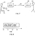
hub station 50 andremote terminal 72 will now be discussed. It will be understood in the following description that the "image processor" or "creator" is athub station 50, while the "customer" or "user" is at aremote terminal 72. - FIG. 7 shows an image processor or digital creator 101 a multiple image sequence viewed on
display 102 by controllingkey board 103. Once the work reaches a degree ofcompleteness communication channel 104 sends the image sequence tocustomer 106viewing display 105. The customer may see the directional image displayed using a number of techniques. For example the images may be viewed on the display as a time sequence as shown in FIG. 8 where between time t0 and t1 the first frame may be displayed between t1 and t2 the second frame may be displayed, between t2 and t3 the third frame may be displayed and so on to simulate the customer moving in front of the image. - For a lenticular image that is meant to appear as a motion image the above display technique can be very realistic, however for an image which is meant to display three-dimensions (that is, a perspective lenticular image) it may be desirable for the customer to use synchronized glasses so that the left eye and right eye show different frames. In this case as shown in FIG. 9 the
customer 106 may seeframes Frame 4 would appear in the right eye andframe 6 would appear in the left eye and then to simulate him moving indirection 301 in front of theimage frame 3 would appear in the right eye andframe 5 in the left eye and then 2 and 4 and 1 and 3 respectively. However if the customer wished to simulate being further back from the image then frames 5 and 6 would appear,frame 5 in the right eye andframe 6 in the left eye. Alternatively by movingcloser frames frame 3 in the right eye andframe 7 in the right eye. To make the appearance more realistic acamera 401 as shown in FIG. 10 may be mounted on top ofdisplay 105 and the camera may be used to track the position of the customer so that as he moves in front of the image the appropriate image appears in the left and right eye. - Another alternative is shown in Figure 11. In the display of a simulated three-dimensional lenticular image as shown in this figure, the customer uses virtual reality headgear and has separate display units in left eye and right eye. As the customer moves, their relative movement is determined by sensing helmet 501. The customer position is communicated from helmet 501 to
processor 502. With this position information, processor may provide the correct views to the customer's right and left eyes, as a function of his position. The "correct" views are those the customer would see at the same position relative to a corresponding actual lenticular image element. Also it will be appreciated that to sweep through the view sequence the customer may control a knob, joystick or mouse to adjust either the speed of sequence or such that the knob, joystick or mouse position controls the views that he sees at any given time, for example moving the mouse may simulate the customer's position so that the mouse position corresponds to the final intended viewing position. - To make the proofing more realistic it may be desired to incorporate for example the lenticular barrier or other directional effects into the image. For example by putting a test image on lenticular material and viewing it with a scanning sensor such that frames 601 602 and 603 correspond to different colors. As the
sensor 605 is moved across alongpath 606 in front of the lenticular material a color analysis by the sensor will indicate the portion of each image being viewed. These image intensity profiles can be thought of as shown in FIG. 13 when plotted against theta across in front of the lenticular material as theprofiles frames location 704 corresponding to being mid-way betweenviews line 604 in FIG. 12 to combine both images giving them the weights of the profile shown. For example at thespecific location 704 the intensity is k1 times the video amplitude of the 602 image plus k2 times the amplitude of the 601 image where the maximum image profile value shown bylevel 715 is 1.0. - Another way to enhance the realism of the proofing is to modify the displayed images to compensate for the size of the lenticules. This is possible because when viewing a lenticular image from any direction each lenticule would generally appear as a band of uniform color across its width so that the finest detail which can be seen across the width of a lenticular would generally correspond to one lenticules width. As a result it is possible to simulate this resolution limitation imposed by the lenticules on the final image by computing the video intensity such as shown in FIG. 14 where 801 is image intensity in a specific direction across the image, this direction being at right angles to the lenticules. Given that lenticular width is defined as shown, the image is broken into components of uniform color and intensity in the direction across the width, where each component is of width "w". Thus, a displayed image is formed in which the area that a lenticule covers of a specific view is rendered unform in the direction at right angles to the lenticule. It will be appreciated that it is also possible to add other characteristics to the displayed image to enhance the realism of viewing a simulated lenticular image.
- Another enhancement of realism is to provide accurate color display with respect to the lenticular image being simulated.
- Images may be preprocessed for display in either
workstation - Referring now to FIG. 15 there is illustrated another aspect of a simulated lenticular image. FIG. 15 shows on the left hand side the tilting of an actual lenticular motion image so than
observer 24 can view each of the images (that is, motion frames) thereon. On the right hand side is shown the same images as they may appear in a corresponding simulated lenticular image observed on adisplay 102. Each of the different images is shown in successive views of the display as 102a through 102d. Eachview 102a to 102d of the simulated lenticular image corresponds to the image that would be expected to be seen on the actual lenticular image when it is in the angular position immediately to that view's left in FIG. 15.Ball 8 is an object in motion through the image sequence. - Note that in a desired
lenticular image element 10 of FIG. 15, the apparent height h1 through h4 of the lenticular image is reduced while the viewer observes the motion image sequence. Thus, the height of animage area 7 appearing ondisplay 102 is correspondingly reduced proceeding throughviews 102a to 102d (the image area having a border 6). Thus, the simulated lenticular image has a displayed image size variation through theimage sequence 102a to 102d which corresponds with change in the angle between the corresponding actual lenticular image and a viewer while observing the sequence in the actual lenticular image. This further enhances the realism of the simulated lenticular image so that the viewer receives an actual lenticular image which appears very similar to what they expect to see based on the simulated lenticular image. - It will be appreciated that the various features discussed above to provide a realistic simulated lenticular image, can be combined for better realism. For example, the simulated lenticular image of FIG. 15 comprising a display of images of the actual lenticular motion image in sequence, may be provided with a luminance variation through the image sequence which corresponds with the expected light distribution, as discussed above in connection with FIGS. 12 through 14. Thus, luminance intensity could be altered as
display 102 shows image frames between each pair ofsuccessive views 102a to 102d, the altered luminance profile being in accordance with FIG. 13. - While the above methods and apparatus have been discussed in connection with lenticular images in particular, it will be appreciated that they may equally be applied to integral images in general.
- The invention has been described with reference to a preferred embodiment. However, it will be appreciated that variations and modifications can be effected by a person of ordinary skill in the art without departing from the scope of the invention.
-
- 1, 2, 3,
- Image Frames
- 4, 5, 6, 7
- 7
- Image Area
- 8
- Ball (Image Element)
- 11
- Lenticular Image
- 12
- Lens Sheet
- 12a, 12b
- Front Side, Back Side
- 13
- Lenticules
- 14
- Sets of Lines
- 21, 22,
- Different Positions of Lenticular Image
- 23
- 24
- Observer
- 42, 43,
- Image Lines
- 45
- 50
- Hub Station
- 54
- Hub Station Processor
- 55
- Memory
- 56
- Converter
- 58
- Printer
- 60
- Alignment Apparatus
- 62, 64
- Physical Media
- 63
- Communication Means
- 66
- Digital Camera
- 70
- Network
- 72
- Remote Terminals
- 80
- Communication Means
- 82
- Remote Terminal Processor
- 83
- Memory
- 101
- Digital Creator
- 102
- Display
- 102a to102d
- Views of Simulated Lenticular Image
- 103
- User Interface
- 104
- Communication Channel
- 105
- Display
- 106
- Customer
- 301
- Direction of Movement
- 401
- Camera
- 501
- Sensing Helmet
- 601,
- Different Colored Frames
- 602, 603
- 604
- Line
- 605
- Sensor
- 606
- Path of Movement
- 701,
- Image Intensity Profiles
- 702, 703
- 704
- Location
- 715
- Level
- 801
- Image Intensity
Claims (10)
- A method for remote approval of lenticular images, comprising:a) at a centralized hub station, receiving a series of images;b) viewing, at a terminal remote from the centralized hub station, a simulated lenticular image using at least some images of the series displayed to simulate viewing an actual lenticular image formed from the images of the series;c) transmitting an approval from the remote terminal to the centralized hub station, for a plurality of the images of the series to be printed as the actual lenticular image;d) at the hub station, printing the actual lenticular image based on the approval.
- A method according to claim 1 additionally comprising, at the hub station, interleaving the images of the series to form the actual lenticular image based on the approval.
- A method according to claim 1 wherein the series of images is a sequence of frames from a motion sequence and the actual lenticular image is a motion lenticular image.
- A method according to claim 1 wherein:the centralized hub station determines interleaved characteristics of a plurality of the images of the series and transmits the resulting interleaved characteristics to the remote terminal; andthe remote terminal forms the simulated lenticular image using the received interleaved characteristics.
- A method according to claim 4 additionally comprising, at the remote terminal, modifying the received interleaved characteristics and transmitting the modifications to the hub station.
- A method according to claim 1 wherein the simulated lenticular image is based on a physical parameter of a lenticular lens sheet, the method additionally comprising, at the hub station, aligning the printed actual lenticular image with a lenticular lens sheet having the physical parameter.
- A method according to claim 1 wherein the physical parameter is selected from lenticular pitch of the lens sheet and an optical parameter of the lenticules.
- A method according to claim 6 wherein the physical parameter is the expected light distribution from observed images viewed through a lenticular lens sheet aligned with the actual lenticular image, as the angle of viewing about the axis of the lenticules is altered.
- An apparatus for printing lenticular images with remote approval, comprising:a) a centralized hub station having:a first communication means for allowing the centralized hub station to communicate with a terminal remote from the hub station;a printer to print a lenticular image based on an approval communicated from a remote hub station;b) a terminal remote from the hub station having:a display means for viewing a simulated lenticular image which uses a plurality of images displayed to simulate viewing an actual lenticular image formed from images of a series;second communication means for communicating with the centralized hub station, including transmitting an approval for a plurality of the image series to be printed as a lenticular image.
- An apparatus according to claim 19 wherein the centralized hub station further has:a memory to store the images of the series;a processor means for interleaving images of the series in accordance with the approval received from the remote terminal.
Applications Claiming Priority (2)
| Application Number | Priority Date | Filing Date | Title |
|---|---|---|---|
| US909789 | 1997-08-12 | ||
| US08/909,789 US5867322A (en) | 1997-08-12 | 1997-08-12 | Remote approval of lenticular images |
Publications (2)
| Publication Number | Publication Date |
|---|---|
| EP0897126A2 true EP0897126A2 (en) | 1999-02-17 |
| EP0897126A3 EP0897126A3 (en) | 1999-06-09 |
Family
ID=25427835
Family Applications (1)
| Application Number | Title | Priority Date | Filing Date |
|---|---|---|---|
| EP98202585A Withdrawn EP0897126A3 (en) | 1997-08-12 | 1998-07-31 | Remote approval of lenticular images |
Country Status (5)
| Country | Link |
|---|---|
| US (1) | US5867322A (en) |
| EP (1) | EP0897126A3 (en) |
| JP (1) | JPH11149134A (en) |
| CN (1) | CN1209704A (en) |
| AU (1) | AU739453B2 (en) |
Cited By (8)
| Publication number | Priority date | Publication date | Assignee | Title |
|---|---|---|---|---|
| WO2005033776A1 (en) * | 2003-10-04 | 2005-04-14 | Koninklijke Philips Electronics N.V. | Optimising brightness control in a 3d image display device |
| FR2868901A1 (en) * | 2004-04-07 | 2005-10-14 | Eastman Kodak Co | METHOD FOR AUTOMATICALLY MOUNTING VIDEO SEQUENCES AND APPARATUS FOR IMPLEMENTING THE METHOD |
| WO2008087632A2 (en) * | 2007-01-15 | 2008-07-24 | Humaneyes Technologies Ltd. | A method and a system for lenticular printing |
| WO2008102366A2 (en) | 2007-02-25 | 2008-08-28 | Humaneyes Technologies Ltd. | A method and a system for calibrating and/or visualizing a multi image display and for reducing ghosting artifacts |
| EP2101200A1 (en) * | 2008-03-14 | 2009-09-16 | Oki Data Corporation | Lenticular lens medium |
| US8190042B1 (en) | 2008-05-16 | 2012-05-29 | Oki Data Americas, Inc. | Electrophotographic printing apparatus |
| US9035968B2 (en) | 2007-07-23 | 2015-05-19 | Humaneyes Technologies Ltd. | Multi view displays and methods for producing the same |
| US10721462B2 (en) | 2017-10-27 | 2020-07-21 | Samsung Electronics Co., Ltd. | Method and apparatus for calibrating parameter of three-dimensional (3D) display apparatus |
Families Citing this family (27)
| Publication number | Priority date | Publication date | Assignee | Title |
|---|---|---|---|---|
| US6448984B1 (en) * | 1998-01-05 | 2002-09-10 | Amiga Development Llc | Displaying layered information using lenticular-like interfaces |
| US6519340B1 (en) * | 1998-03-17 | 2003-02-11 | The University Of Connecticut | Method and apparatus for encryption using partial information |
| US6198544B1 (en) * | 1998-04-08 | 2001-03-06 | Eastman Kodak Company | Method and system for capturing images from a video tape for the purpose of creating a motion card |
| US5967032A (en) * | 1998-05-21 | 1999-10-19 | Lti Corporation | Printing process using a thin sheet lenticular lens material |
| US6211896B1 (en) * | 1998-12-16 | 2001-04-03 | Eastman Kodak Company | Method for producing lenticular images |
| US6247650B1 (en) * | 1998-12-21 | 2001-06-19 | Eastman Kodak Company | Integral image element with display control parameters |
| US7961201B1 (en) | 2000-12-21 | 2011-06-14 | Cognex Corporation | Method and apparatus for producing graphical machine vision content for distribution via a network |
| US7383536B1 (en) * | 2000-12-29 | 2008-06-03 | Petry John | Remote machine vision application program development method |
| US7962898B1 (en) * | 2000-12-29 | 2011-06-14 | Cognex Corporation | Optimized distribution of machine vision processing |
| US20020114077A1 (en) * | 2001-01-23 | 2002-08-22 | Bahram Javidi | Integral three-dimensional imaging with digital reconstruction |
| US6894719B2 (en) * | 2001-08-23 | 2005-05-17 | Eastman Kodak Company | Method and apparatus for creating a preselected lenticular image |
| US20060256436A1 (en) * | 2002-01-23 | 2006-11-16 | The University Of Connecticut | Integral three-dimensional imaging with digital reconstruction |
| US7787672B2 (en) | 2004-11-04 | 2010-08-31 | Dr Systems, Inc. | Systems and methods for matching, naming, and displaying medical images |
| US7920152B2 (en) | 2004-11-04 | 2011-04-05 | Dr Systems, Inc. | Systems and methods for viewing medical 3D imaging volumes |
| US7885440B2 (en) * | 2004-11-04 | 2011-02-08 | Dr Systems, Inc. | Systems and methods for interleaving series of medical images |
| US7660488B2 (en) | 2004-11-04 | 2010-02-09 | Dr Systems, Inc. | Systems and methods for viewing medical images |
| US7970625B2 (en) | 2004-11-04 | 2011-06-28 | Dr Systems, Inc. | Systems and methods for retrieval of medical data |
| GB2422737A (en) * | 2005-01-26 | 2006-08-02 | Sharp Kk | Multiple-view display and display controller |
| US7953614B1 (en) | 2006-11-22 | 2011-05-31 | Dr Systems, Inc. | Smart placement rules |
| ITTO20070620A1 (en) * | 2007-08-31 | 2009-03-01 | Giancarlo Capaccio | SYSTEM AND METHOD FOR PRESENTING VISUAL DATA DETACHED IN MULTI-SPECTRAL IMAGES, MERGER, AND THREE SPACE DIMENSIONS. |
| EP3541070B8 (en) * | 2008-06-27 | 2023-12-20 | Leia Inc. | Autostereoscopic display device and method |
| JP2009223313A (en) * | 2009-03-05 | 2009-10-01 | Oki Data Corp | Lenticular lens medium |
| JP5338424B2 (en) | 2009-03-25 | 2013-11-13 | セイコーエプソン株式会社 | Recording apparatus and conveying method |
| US9495604B1 (en) | 2013-01-09 | 2016-11-15 | D.R. Systems, Inc. | Intelligent management of computerized advanced processing |
| JP2015037876A (en) * | 2014-09-29 | 2015-02-26 | セイコーエプソン株式会社 | Recording device and conveying method |
| US20170039321A1 (en) | 2015-04-30 | 2017-02-09 | D.R. Systems, Inc. | Database systems and interactive user interfaces for dynamic interaction with, and sorting of, digital medical image data |
| JP2017055374A (en) * | 2015-09-11 | 2017-03-16 | 佐藤 正志 | Naked eye 3D video transmission display system |
Citations (5)
| Publication number | Priority date | Publication date | Assignee | Title |
|---|---|---|---|---|
| EP0588332A2 (en) * | 1992-09-16 | 1994-03-23 | Eastman Kodak Company | Method and apparatus for optimizing the resolution of images which have an apparent depth |
| WO1994016392A1 (en) * | 1993-01-06 | 1994-07-21 | Image Technology International, Inc. | A filmless method and apparatus for producing 3-d photographs |
| GB2286944A (en) * | 1994-02-25 | 1995-08-30 | Eastman Kodak Co | System for selecting photographic images |
| US5477353A (en) * | 1993-04-21 | 1995-12-19 | Olympus Optical Co., Ltd. | Photographic image processing system having laboratory unit for processing film and photographer unit for supplying printing information |
| US5519794A (en) * | 1994-04-01 | 1996-05-21 | Rotaventure L.L.C. | Computer-generated autostereography method and apparatus |
Family Cites Families (13)
| Publication number | Priority date | Publication date | Assignee | Title |
|---|---|---|---|---|
| US3028785A (en) * | 1962-04-10 | Apparatus for facilitating the reproduction or | ||
| US2652326A (en) * | 1949-03-26 | 1953-09-15 | Sperry Corp | Art of making stereoscopic pictures |
| US3895867A (en) * | 1971-08-12 | 1975-07-22 | Dimensional Dev Corp | Three dimensional pictures and method of composing them |
| US4963959A (en) * | 1989-11-20 | 1990-10-16 | Drewlo Kenneth G | Three-dimensional cathode ray tube display |
| US5276478A (en) * | 1992-05-19 | 1994-01-04 | Eastman Kodak Company | Method and apparatus for optimizing depth images by adjusting print spacing |
| US5278608A (en) * | 1992-05-19 | 1994-01-11 | Eastman Kodak Company | Electronically printed depth photography system with improved viewing range |
| US5479270A (en) * | 1992-05-19 | 1995-12-26 | Eastman Kodak Company | Method and apparatus for aligning depth images |
| WO1994010805A1 (en) * | 1992-11-05 | 1994-05-11 | Perceptual Images | Three dimensional imaging system using shutter and back to back lenticular screen |
| US5712732A (en) * | 1993-03-03 | 1998-01-27 | Street; Graham Stewart Brandon | Autostereoscopic image display adjustable for observer location and distance |
| US5424553A (en) * | 1994-05-16 | 1995-06-13 | Eastman Kodak Company | Method for aligning a lenticular material for printing |
| US5475419A (en) * | 1994-06-29 | 1995-12-12 | Carbery Dimensions, Ltd. | Apparatus and method for three-dimensional video |
| US5731883A (en) * | 1996-04-10 | 1998-03-24 | Eastman Kodak Company | Apparatus and method for producing integral image elements |
| US5786902A (en) * | 1996-09-17 | 1998-07-28 | Eastman Kodak Company | Photographic printer and method of digitally correcting for a photographic printer |
-
1997
- 1997-08-12 US US08/909,789 patent/US5867322A/en not_active Expired - Fee Related
-
1998
- 1998-07-31 EP EP98202585A patent/EP0897126A3/en not_active Withdrawn
- 1998-08-11 AU AU78962/98A patent/AU739453B2/en not_active Ceased
- 1998-08-11 CN CN98116273A patent/CN1209704A/en active Pending
- 1998-08-11 JP JP10226785A patent/JPH11149134A/en active Pending
Patent Citations (5)
| Publication number | Priority date | Publication date | Assignee | Title |
|---|---|---|---|---|
| EP0588332A2 (en) * | 1992-09-16 | 1994-03-23 | Eastman Kodak Company | Method and apparatus for optimizing the resolution of images which have an apparent depth |
| WO1994016392A1 (en) * | 1993-01-06 | 1994-07-21 | Image Technology International, Inc. | A filmless method and apparatus for producing 3-d photographs |
| US5477353A (en) * | 1993-04-21 | 1995-12-19 | Olympus Optical Co., Ltd. | Photographic image processing system having laboratory unit for processing film and photographer unit for supplying printing information |
| GB2286944A (en) * | 1994-02-25 | 1995-08-30 | Eastman Kodak Co | System for selecting photographic images |
| US5519794A (en) * | 1994-04-01 | 1996-05-21 | Rotaventure L.L.C. | Computer-generated autostereography method and apparatus |
Cited By (15)
| Publication number | Priority date | Publication date | Assignee | Title |
|---|---|---|---|---|
| WO2005033776A1 (en) * | 2003-10-04 | 2005-04-14 | Koninklijke Philips Electronics N.V. | Optimising brightness control in a 3d image display device |
| FR2868901A1 (en) * | 2004-04-07 | 2005-10-14 | Eastman Kodak Co | METHOD FOR AUTOMATICALLY MOUNTING VIDEO SEQUENCES AND APPARATUS FOR IMPLEMENTING THE METHOD |
| WO2005099246A1 (en) * | 2004-04-07 | 2005-10-20 | Eastman Kodak Company | Method for automatically editing video sequences and camera for implementing the method |
| WO2008087632A2 (en) * | 2007-01-15 | 2008-07-24 | Humaneyes Technologies Ltd. | A method and a system for lenticular printing |
| WO2008087632A3 (en) * | 2007-01-15 | 2008-12-31 | Humaneyes Technologies Ltd | A method and a system for lenticular printing |
| US8520060B2 (en) | 2007-02-25 | 2013-08-27 | Humaneyes Technologies Ltd. | Method and a system for calibrating and/or visualizing a multi image display and for reducing ghosting artifacts |
| WO2008102366A2 (en) | 2007-02-25 | 2008-08-28 | Humaneyes Technologies Ltd. | A method and a system for calibrating and/or visualizing a multi image display and for reducing ghosting artifacts |
| US9035968B2 (en) | 2007-07-23 | 2015-05-19 | Humaneyes Technologies Ltd. | Multi view displays and methods for producing the same |
| EP2101200A1 (en) * | 2008-03-14 | 2009-09-16 | Oki Data Corporation | Lenticular lens medium |
| US7872805B2 (en) | 2008-03-14 | 2011-01-18 | Oki Data Corporation | Lenticular lens medium |
| US7852563B2 (en) | 2008-03-14 | 2010-12-14 | Oki Data Corporation | Lenticular lens medium |
| EP2101199A1 (en) | 2008-03-14 | 2009-09-16 | Oki Data Corporation | Lenticular lens medium |
| US8190042B1 (en) | 2008-05-16 | 2012-05-29 | Oki Data Americas, Inc. | Electrophotographic printing apparatus |
| US10721462B2 (en) | 2017-10-27 | 2020-07-21 | Samsung Electronics Co., Ltd. | Method and apparatus for calibrating parameter of three-dimensional (3D) display apparatus |
| US11284059B2 (en) | 2017-10-27 | 2022-03-22 | Samsung Electronics Co., Ltd. | Method and apparatus for calibrating parameter of three-dimensional (3D) display apparatus |
Also Published As
| Publication number | Publication date |
|---|---|
| AU7896298A (en) | 1999-02-25 |
| EP0897126A3 (en) | 1999-06-09 |
| JPH11149134A (en) | 1999-06-02 |
| CN1209704A (en) | 1999-03-03 |
| US5867322A (en) | 1999-02-02 |
| AU739453B2 (en) | 2001-10-11 |
Similar Documents
| Publication | Publication Date | Title |
|---|---|---|
| US5867322A (en) | Remote approval of lenticular images | |
| US5581402A (en) | Method for producing an improved stereoscopic picture and stereoscopic picture obtained according to this method | |
| US5455689A (en) | Electronically interpolated integral photography system | |
| US7845799B2 (en) | Three-dimensional image communication terminal and projection-type three-dimensional image display apparatus | |
| US5278608A (en) | Electronically printed depth photography system with improved viewing range | |
| USRE35029E (en) | Computer-generated autostereography method and apparatus | |
| EP0740282B1 (en) | Device and method for producing lenticular images with motion | |
| US6795241B1 (en) | Dynamic scalable full-parallax three-dimensional electronic display | |
| US6665003B1 (en) | System and method for generating and displaying panoramic images and movies | |
| CN100511124C (en) | Free multi visul point polyprojecting 3D displaying system and method | |
| US20020114078A1 (en) | Resolution modulation in microlens image reproduction | |
| EP1275999A1 (en) | Device for reproducing three-dimensional image with background | |
| US5828495A (en) | Lenticular image displays with extended depth | |
| US5337096A (en) | Method for generating three-dimensional spatial images | |
| JPH0652291A (en) | Method and apparatus for forming geometric solid picture using computer graphics | |
| US4671632A (en) | Three-dimensional display apparatus | |
| US5905593A (en) | Method and apparatus of producing 3D video by correcting the effects of video monitor on lenticular layer | |
| US6366407B2 (en) | Lenticular image product with zoom image effect | |
| US5556184A (en) | Imaginograph | |
| US6791541B1 (en) | Three-dimensional image system | |
| WO2000035204A1 (en) | Dynamically scalable full-parallax stereoscopic display | |
| JP5283643B2 (en) | Stereo slide or stereo photo print, printer, stereo slide mount and print paper | |
| McCartney et al. | Telecommunications applications for 3D imaging systems | |
| McCartney et al. | Autostereoscopic 3-D imaging systems for telecommunications applications | |
| CZ241098A3 (en) | Method of stereoscopic presentation and apparatus for making the same |
Legal Events
| Date | Code | Title | Description |
|---|---|---|---|
| PUAI | Public reference made under article 153(3) epc to a published international application that has entered the european phase |
Free format text: ORIGINAL CODE: 0009012 |
|
| AK | Designated contracting states |
Kind code of ref document: A2 Designated state(s): DE FR GB |
|
| AX | Request for extension of the european patent |
Free format text: AL;LT;LV;MK;RO;SI |
|
| PUAL | Search report despatched |
Free format text: ORIGINAL CODE: 0009013 |
|
| AK | Designated contracting states |
Kind code of ref document: A3 Designated state(s): AT BE CH CY DE DK ES FI FR GB GR IE IT LI LU MC NL PT SE |
|
| AX | Request for extension of the european patent |
Free format text: AL;LT;LV;MK;RO;SI |
|
| RIC1 | Information provided on ipc code assigned before grant |
Free format text: 6G 02B 27/22 A, 6G 03B 35/24 B |
|
| 17P | Request for examination filed |
Effective date: 19991117 |
|
| AKX | Designation fees paid |
Free format text: DE FR GB |
|
| GRAP | Despatch of communication of intention to grant a patent |
Free format text: ORIGINAL CODE: EPIDOSNIGR1 |
|
| STAA | Information on the status of an ep patent application or granted ep patent |
Free format text: STATUS: THE APPLICATION IS DEEMED TO BE WITHDRAWN |
|
| 18D | Application deemed to be withdrawn |
Effective date: 20040128 |