EP0897110A2 - Material testing machine - Google Patents
Material testing machine Download PDFInfo
- Publication number
- EP0897110A2 EP0897110A2 EP98115079A EP98115079A EP0897110A2 EP 0897110 A2 EP0897110 A2 EP 0897110A2 EP 98115079 A EP98115079 A EP 98115079A EP 98115079 A EP98115079 A EP 98115079A EP 0897110 A2 EP0897110 A2 EP 0897110A2
- Authority
- EP
- European Patent Office
- Prior art keywords
- test piece
- control
- gain
- displacement
- material testing
- Prior art date
- Legal status (The legal status is an assumption and is not a legal conclusion. Google has not performed a legal analysis and makes no representation as to the accuracy of the status listed.)
- Withdrawn
Links
Images


Classifications
-
- G—PHYSICS
- G01—MEASURING; TESTING
- G01N—INVESTIGATING OR ANALYSING MATERIALS BY DETERMINING THEIR CHEMICAL OR PHYSICAL PROPERTIES
- G01N3/00—Investigating strength properties of solid materials by application of mechanical stress
- G01N3/08—Investigating strength properties of solid materials by application of mechanical stress by applying steady tensile or compressive forces
- G01N3/10—Investigating strength properties of solid materials by application of mechanical stress by applying steady tensile or compressive forces generated by pneumatic or hydraulic pressure
-
- G—PHYSICS
- G01—MEASURING; TESTING
- G01N—INVESTIGATING OR ANALYSING MATERIALS BY DETERMINING THEIR CHEMICAL OR PHYSICAL PROPERTIES
- G01N3/00—Investigating strength properties of solid materials by application of mechanical stress
-
- G—PHYSICS
- G05—CONTROLLING; REGULATING
- G05B—CONTROL OR REGULATING SYSTEMS IN GENERAL; FUNCTIONAL ELEMENTS OF SUCH SYSTEMS; MONITORING OR TESTING ARRANGEMENTS FOR SUCH SYSTEMS OR ELEMENTS
- G05B19/00—Program-control systems
- G05B19/02—Program-control systems electric
- G05B19/18—Numerical control [NC], i.e. automatically operating machines, in particular machine tools, e.g. in a manufacturing environment, so as to execute positioning, movement or co-ordinated operations by means of program data in numerical form
- G05B19/19—Numerical control [NC], i.e. automatically operating machines, in particular machine tools, e.g. in a manufacturing environment, so as to execute positioning, movement or co-ordinated operations by means of program data in numerical form characterised by positioning or contouring control systems, e.g. to control position from one programmed point to another or to control movement along a programmed continuous path
- G05B19/33—Numerical control [NC], i.e. automatically operating machines, in particular machine tools, e.g. in a manufacturing environment, so as to execute positioning, movement or co-ordinated operations by means of program data in numerical form characterised by positioning or contouring control systems, e.g. to control position from one programmed point to another or to control movement along a programmed continuous path using an analogue measuring device
-
- G—PHYSICS
- G05—CONTROLLING; REGULATING
- G05D—SYSTEMS FOR CONTROLLING OR REGULATING NON-ELECTRIC VARIABLES
- G05D15/00—Control of mechanical force or stress; Control of mechanical pressure
- G05D15/01—Control of mechanical force or stress; Control of mechanical pressure characterised by the use of electric means
-
- G—PHYSICS
- G05—CONTROLLING; REGULATING
- G05B—CONTROL OR REGULATING SYSTEMS IN GENERAL; FUNCTIONAL ELEMENTS OF SUCH SYSTEMS; MONITORING OR TESTING ARRANGEMENTS FOR SUCH SYSTEMS OR ELEMENTS
- G05B2219/00—Program-control systems
- G05B2219/30—Nc systems
- G05B2219/37—Measurements
- G05B2219/37206—Inspection of surface
-
- G—PHYSICS
- G05—CONTROLLING; REGULATING
- G05B—CONTROL OR REGULATING SYSTEMS IN GENERAL; FUNCTIONAL ELEMENTS OF SUCH SYSTEMS; MONITORING OR TESTING ARRANGEMENTS FOR SUCH SYSTEMS OR ELEMENTS
- G05B2219/00—Program-control systems
- G05B2219/30—Nc systems
- G05B2219/41—Servomotor, servo controller till figures
- G05B2219/41029—Adjust gain as function of position error and position
-
- G—PHYSICS
- G05—CONTROLLING; REGULATING
- G05B—CONTROL OR REGULATING SYSTEMS IN GENERAL; FUNCTIONAL ELEMENTS OF SUCH SYSTEMS; MONITORING OR TESTING ARRANGEMENTS FOR SUCH SYSTEMS OR ELEMENTS
- G05B2219/00—Program-control systems
- G05B2219/30—Nc systems
- G05B2219/41—Servomotor, servo controller till figures
- G05B2219/41388—Observe input torque and feedback position, estimate reaction torque
-
- G—PHYSICS
- G05—CONTROLLING; REGULATING
- G05B—CONTROL OR REGULATING SYSTEMS IN GENERAL; FUNCTIONAL ELEMENTS OF SUCH SYSTEMS; MONITORING OR TESTING ARRANGEMENTS FOR SUCH SYSTEMS OR ELEMENTS
- G05B2219/00—Program-control systems
- G05B2219/30—Nc systems
- G05B2219/50—Machine tool, machine tool null till machine tool work handling
- G05B2219/50073—Signature analysis, store forces during test, compare with real ones during assemby
Definitions
- the present invention relates to a material testing machine, and more particularly, to an electrohydraulic servo-controlled material testing machine.
- An electrohydraulic servo-controlled material testing machine which is comprised of a controller for supplying, via a servo amplifier, an electric signal input to an electrohydraulic servo valve provided between a hydraulic power source and a hydraulic actuator such as hydraulic cylinder, the electric signal input varying in accordance with a target displacement of a movable part of the actuator.
- the quantity of fluid output from the servo valve varies in response to the electric signal input, and the movable part of the hydraulic cylinder is displaced at a speed proportional to the fluid quantity, whereby a load is applied to a test piece held between the cylinder movable part and a main body of the testing machine.
- An actual displacement of the cylinder movable part is detected and is supplied as a feedback signal to the controller. Under the control of the controller, a feedback control is carried out to cause the actual displacement to close to a target displacement.
- the term "displacement of a test piece” indicates the displacement of one end of the test piece coupled to a movable part of an actuator which is caused by the displacement of the movable part of the actuator.
- the term “displacement of the test piece” indicates the sum of displacements of opposite ends of the test piece caused by the displacement of the two movable parts of the actuators. That is, the term “displacement of the test piece” indicates deformation of the test piece caused by the displacement of the movable part(s) of the actuator.
- the term "servo system” indicates a system mainly comprised of an actuator, a servo amplifier, and a servo valve.
- control system indicates a system mainly comprised of a servo system and a controller for controlling the operation of the servo system.
- control loop or “feedback control loop” indicates a loop mainly comprised of a servo system, a controller, and a test piece.
- force control system indicates a control system for carrying out a feedback control with use of an actual force applied to the test piece, as the controlled variable
- the term “displacement control system” indicates a system for executing a feedback control using, as a controlled variable, an actual displacement of the test piece.
- load indicates a broadly defined load which includes a force applied to the test piece and generally referred to as a load, and which also includes the displacement of the test piece.
- control objective value indicates a target load.
- a typical electrohydraulic servo-controlled material testing machine performs material testing, while controlling the actual load given to the test piece (the actual force applied to or the actual displacement of the test piece) to the target load in a feedback manner.
- the control gain for the feedback control, thereby performing the material testing efficiently and stably because the control response lowers so that much time is required for material testing if the control gain is excessively small, whereas hunting phenomenon occurs so that the stability and reliability of the testing are impaired, sometimes leading to test piece breakage if the control gain is excessively large.
- the optimum control gain for the feedback control varies depending on mechanical properties, especially stiffness (elastic constant), of the test piece. For this reason, in the case of material testing as for a test piece whose stiffness is unknown, preliminary testing is heretofore carried out repeatedly while changing the control gain, to thereby determine the optimum control gain in a trial and error manner. This requires labor and time.
- the stiffness of the test piece varies in dependence on the load given to the test piece. Especially, the stiffness largely varies if the test piece is in its elastic deformation region. In other words, the optimum control gain for feedback control may change as the stiffness changes, even in the course of material testing, causing the feedback control to be improper so that the testing efficiency and stability may be impaired.
- An electrohydraulic servo-controlled material testing machine may be of a type having a force control system for feedback-controlling the actual force applied to the test piece to the target force and a displacement control system for feedback-controlling the actual displacement of the test piece to the target displacement, and adapted to select a desired one of these control systems to carry out the feedback control in a force control mode or a displacement control mode. Generally, either one of the control modes is selected during the testing in accordance with instructions given by an operator.
- the control gain for the control loop which is comprised of the servo system, the controller, and the test piece especially the control gain for the controller largely differs according to whether the testing machine operates in the force control mode or in the displacement control mode. That is, the control gain for the controller is set to be small in the force control mode, whereas it is set to be large in the displacement control mode.
- the mechanical properties, especially the stiffness of the test piece generally varies in dependence on the load given to the test piece, and the proper control gain greatly changes depending on the mechanical properties of the test piece. If the force control mode is changed over to the displacement control mode in a condition the load is kept applied, the applied load abruptly changes attributable to the difference of control gain between the two control modes, so that a large shock may be applied to the test piece.
- An object of the present invention is to provide a material testing machine capable of always optimizing the control gain for feedback control even if mechanical properties of a test piece vary during material testing, to thereby carry out material testing with accuracy in a stable manner.
- a material testing machine for measuring a mechanical property of a test piece based on a load given to the test piece and a mechanical change (e.g., displacement or distortion) generated in the test piece, while feedback-controlling an operation of a servo system including a hydraulic actuator which gives the load to the test piece by means of a controller such that actual load applied to the test piece coincides with target load.
- a servo system including a hydraulic actuator which gives the load to the test piece by means of a controller such that actual load applied to the test piece coincides with target load.
- the material testing machine comprises: gain setting means for setting the control gain for the feedback control performed during material testing; estimating means for estimating a mechanical property of the test piece based on an actual load and a mechanical change in the test piece which are periodically detected during the material testing performed while carrying out the feedback control; and gain correcting means for correcting the control gain set by the gain setting means in accordance with the estimated mechanical property.
- the control gain for the feedback control is corrected based on the mechanical property of the test piece estimated on the basis of the load and the mechanical change (e.g., displacement or distortion) in the test piece, periodically detected during the material testing. If the control gain set by the gain setting means is deviated from an optimum value or if the control gain is deviated from the optimum value as the mechanical change occurs in the test piece during the material testing, the control gain is corrected to be optimized.
- the material testing can be made stably with high accuracy, while always giving a proper load to the test piece.
- the estimating means estimates stiffness of the test piece based on the actual load and the actual displacement of the test piece which are periodically detected during the material testing.
- an optimum control gain can be attained by correcting the control gain based on the result of estimation in respect of the stiffness of the test piece which especially affects on the control gain.
- initial setting is made to set the initial value of the control gain for the feedback control performed during the material testing.
- a load is given to the test piece while performing a feedback control similar to the feedback control performed during the material testing. Further, the actual load of and the mechanical change in the test piece are detected, and the mechanical property of the test piece is estimated.
- the gain setting means causes the control gain to gradually increase from the minimum value of the control gain.
- the gain correcting means corrects the control gain to thereby set the initial value of the control gain, based on the estimated mechanical property of the test piece.
- the estimated mechanical property is determined by the estimating means based on the actual load applied to and the mechanical change generated in the test piece which are observed when a mechanical change in the test piece is detected during the initial setting.
- the material testing is started after the initial value of the control gain is set.
- the material testing can be started after the initial value of the control gain for the control system is properly set, and hence the material testing can be carried out without applying an undesired excessive load to the test piece.
- the gain correcting means corrects the control gain set by the gain setting means to coincide with the control gain which corresponds to the estimated mechanical property determined by the estimating means, by searching a table in which the control gain for every type of test piece is set in advance as a function of mechanical property of test piece.
- an optimum control gain for the feedback control to be performed during the material testing can be set in advance, thereby easily efficiently stabilizing the operation of the servo system during the material testing.
- the material testing can be carried out with accuracy in a stabilized manner.
- the material testing machine further comprises load maintaining means for maintaining load observed at a time when a minute change in the test piece (e.g., a minute change in actual load given to the test piece or a minute mechanical change in the test piece) is detected while applying a gradually increasing load prior to material testing; and initial gain setting means for setting an initial value of the control gain for the feedback control.
- the estimating means estimates a mechanical property of the test piece based on actual load and a mechanical change of the test piece respectively detected after a displacement of the test piece is stabilized while the load observed when the minute change in the test piece was detected is maintained.
- the initial gain setting means sets the initial value of the control gain in accordance with the mechanical property of the test piece estimated by the estimating means while the load is maintained.
- the mechanical property of the test piece can be accurately estimated within a short period of time, without giving an undesired load to the test piece. Further, the initial value of the control gain suited to the estimated mechanical property can be automatically set. Thus, material testing can be made efficiently with ease in respect of various test pieces including ones whose mechanical property is unknown.
- a mechanical property e.g., stiffness
- the initial gain setting means sets an initial value of a control gain for the controller in accordance with the estimated mechanical property of the test piece determined by the estimating means.
- the initial value of the control gain for the feedback control (or for a control loop including the servo system, the controller, and the test piece) can be properly set with ease.
- the initial setting means sets the control gain at a minimum value of the control gain when giving the load to the test piece is started prior to material testing, and thereafter the control gain is gradually increased with elapse of time.
- the minute change in the test piece is detected when a mechanical change in the test piece beyond detecting resolution of a detector is detected.
- the initial gain setting means searches a table in which the control gain is stored beforehand as a function of the mechanical property of the test piece, to thereby set the initial value of the control gain based on the mechanical property estimated by the estimating means.
- the initial value of the control gain suitable for material testing can be automatically set with use of the relationship between mechanical properties of various test pieces and optimum control gains acquired in advance.
- the material testing machine comprises: a force control system including a controller for feedback-controlling the operation of the servo system based on an actual force applied to the test piece, the actual force serving as a controlled variable in the feedback control; a displacement control system including a controller for feedback-controlling the operation of the servo system based on an actual displacement of the test piece, the actual displacement serving as a controlled variable in the feedback control; and control system changeover means for selectively operating either the force control system or the displacement control system.
- a force control system including a controller for feedback-controlling the operation of the servo system based on an actual force applied to the test piece, the actual force serving as a controlled variable in the feedback control
- a displacement control system including a controller for feedback-controlling the operation of the servo system based on an actual displacement of the test piece, the actual displacement serving as a controlled variable in the feedback control
- control system changeover means for selectively operating either the force control system or the displacement control system.
- the control system changeover means makes initial setting of a control output value to be supplied from the controller in the post-changeover control system, based on a control output value supplied from the controller in the pre-changeover control system to the servo system just before the changeover, and then makes the control system changeover.
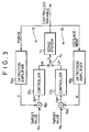
- the testing machine is so configured as to supply a pressurized fluid (fluid pressure) from a hydraulic source 4 to an actuator 3, comprised of a hydraulic cylinder, through a servo valve 5 to operate a movable rod 3b of the actuator 3, thereby providing a load to a test piece S which is held between a stationary chuck 2a provided on the side of a frame of a machine body and a movable chuck 3a provided on the actuator-side.
- the stationary chuck 2a may be removed and a die may be provided instead of the movable chuck 3a, so as to attach the test piece S between the die 3a and a load cell 1.
- a controller 8c of a control section 8 which is comprised of a microcomputer and the like inputs the detected force, displacement and distortion, and controls the operation of the servo valve 5 via a servo amplifier 9 in a feedback manner, with use of a control gain which is set by a control gain setting section 8e, so as to reduce an error between the force detected by the load cell 1 and a target force given from a signal generator 8d of the control section 8 to zero.
- the hydraulic actuator 3 is servo-controlled by the servo feedback control system to adjust a force (more generally, load) applied to the test piece S.
- the electrohydraulic servo control system is represented by a feedback control loop, as shown in Fig. 2. More specifically, the control system comprises an error unit 8b for determining an error ⁇ between a control objective value (a target load or a target displacement, for example) and an output of a detection amplifier 8a which indicates a change (an actual force or an actual displacement) generated in the test piece S, and a controller 8c for controlling, via a servo amplifier 9, the operation of the servo valve 5 in accordance with the error determined by the error unit 8b.
- the control system controls the operation of the servo valve 5 so as to reduce the error ⁇ to zero, thereby hydraulically driving the actuator 3 to adjust the load applied to the test piece S.
- the feedback control system of the testing machine preferably comprises a force control system 12 for feedback controlling the operation of the servo system 11, including the hydraulic actuator 3, servo valve 5 and servo amplifier 9 shown in Fig. 2, in accordance with an error ⁇ eK between an actual force K applied to the test piece and a target force RK; a displacement control system 13 for carrying out the feedback control in accordance with an error ⁇ eH between an actual displacement of the test piece S and a target displacement RH; and a control system-changeover means (selection switch) 14 for selectively operating the force control system 12 or the displacement control system 13.
- a force control system 12 for feedback controlling the operation of the servo system 11, including the hydraulic actuator 3, servo valve 5 and servo amplifier 9 shown in Fig. 2, in accordance with an error ⁇ eK between an actual force K applied to the test piece and a target force RK
- a displacement control system 13 for carrying out the feedback control in accordance with an error ⁇ eH between an actual displacement of the test piece S and a
- reference numeral 15a denotes a detection amplifier for detecting an actual force K from an output of the load cell 1; and 15b denotes a detection amplifier for detecting an actual displacement from an output of the displacement gauge 6.
- Reference numerals 16a and 16b denote error units for determining the error ⁇ eK between actual force K and target force RK and the error ⁇ EH between actual displacement H and target displacement RH, respectively.
- reference numerals 17a and 17b denotes controllers for generating control objective values UK and UH by multiplying the errors ⁇ eK and ⁇ eH by predetermined control gains, respectively.
- the controller 17a supplies the servo system 11 with the control objective value UK to carry out the feedback control in a force control mode
- the controller 17b supplies the servo system 11 with the control objective value UH to effect the feedback control in a displacement control mode.
- control section 8 has a function of automatically optimally setting the control gain in the feedback control loop in accordance with a mechanical property (preferably, stiffness) of the test piece S prior to the start of material testing, to thereby easily carry out material testing in respect of test pieces whose stiffness is unknown.
- the testing machine has various functions which are as follows:
- a first function is to monitor a change in actual force applied to the test piece S or a mechanical change, i.e., a change in displacement or distortion of the test piece S. Preferably, a change in displacement is monitored.
- a second function is to hold a load applied to the test piece S as it is when a minute change of the test piece S, e.g., a minute displacement beyond a measurement resolution of the displacement gauge 6 is detected.
- a third function is to detect the actual force and the actual displacement of the test piece in a condition that the mechanical change, e.g., displacement, is stabilized.
- a fourth function is to estimate an elastic constant KL of the test piece S based on a relationship between the detected actual force applied to the test piece and the actual displacement of the test piece, and a fifth function is to automatically set the control gain in the feedback control loop in accordance with the estimated elastic constant KL.
- the operation of the actuator 3 is controlled while gradually increasing the control gain in the feedback control loop from its minimum value, as shown by the dotted line C in Fig. 4, to thereby gradually increase the load, e.g., force, applied to the test piece S, as shown by the solid line D in Fig. 4.
- the application of force is continued until a minor displacement slightly beyond the measurement resolution of the displacement gauge 6 is detected (processing time period T1).
- a maximum force applicable to the test piece S in the automatic control gain setting processing is preferably restricted up to a value which is 30 to 50% of a maximum target force (shown by the horizontal line portion of the two-dotted-chain line in Fig. 4) for material testing effected after the automatic control gain setting processing, so as to prevent the test piece S from being applied with a large force during the control gain setting.
- the maximum force permitted in the control gain setting may be determined by an estimated mechanical property of the test piece S.
- the operational state of the actuator 3 is held for a predetermined period of time (processing time period T2), thereby holding the force applied to the test piece S at that time, until the displacement of the test piece S is stabilized, as shown by the solid line F in Fig. 4.
- processing time period T2 the operational state of the actuator 3 is held for a predetermined period of time (processing time period T2), thereby holding the force applied to the test piece S at that time, until the displacement of the test piece S is stabilized, as shown by the solid line F in Fig. 4.
- the displacement of the test piece is stabilized within a relatively short period of time, as shown by the time-dependent displacement characteristic line A in Fig. 4.
- the test piece displacement is stabilized after it changes to a certain extent, as shown by the characteristic line B in Fig. 4.
- the time period T2 during which the force is kept unchanged is determined to have a sufficient time length by taking account of the fact that the time period required for the test piece to be stabilized varies depending on the elastic constant of the test piece
- the actual force and the actual displacement of the test piece are detected a multiple number of times (processing time period T3) each.
- the force/displacement detection is repeatedly carried out 100 to 200 times, for instance, to cancel out detection errors.
- an average of detected forces and an average of detected displacements are determined, and the elastic constant KL of the test piece S is estimated by dividing the average force by the average displacement (processing time period T4).
- an optimum control gain to be set in the feedback control loop is determined based on the estimated elastic constant KL, and the determined optimum control gain is initially set.
- optimum control gains in respect of various test pieces S whose elastic constants are known are determined in advance, while optimally operating the testing machine under the control of the servo control system of the machine. Then, by arranging these pieces of data, tabulated data indicating the relationship which is proper to the servo control system is obtained. Furthermore, if a new relationship between the elastic constant KL and the optimum control gain is attained during the material testing, the testing machine learns such actual data and renews the table data.
- the control loop of the testing machine is configured as a closed-loop transfer system which includes, as shown in Fig. 2, the servo amplifier 9, servo valve 5, actuator 3 and test piece S (load).
- the optimum control gain should be set, e.g., in the controller 8c, by taking the transfer system (transfer function) proper to the testing machine and the load transfer system (transfer function) which depends on mechanical properties of the test piece S.
- Fig. 5 exemplarily shows the optimum control gain, corresponding to the elastic constant KL of the test piece S, in the displacement control system in which the operation of the actuator 3 is servo-controlled based on the displacement of the test piece S.
- the optimum proportional gain KP for the displacement control system is shown as a function of elastic constant KL.
- An optimum elastic constant KL vs. integral gain KI characteristic line is similar to that shown in Fig. 5 for the proportional gain KP.
- FIG. 6 shows, by way of example, the optimum proportional gain KP and the optimum integral gain KI, corresponding to the elastic constant KL of the test piece S, for the force control system in which the operation of the actuator 3 is servo-controlled based on the force applied to the test piece S.
- the testing machine Prior to the automatic control gain setting processing, the testing machine is operated with use of a large number of test pieces S whose elastic constants KL, as a whole, vary to cover the entire elastic constant region in which elastic constants of various test pieces to be subject to material testing vary.
- a force applied to the test piece S is caused to gradually increase until a minute displacement of the test piece S is detected, as mentioned before, in order to estimate the elastic constant K of the test piece S.
- the elastic constant KL and the proportional gain KP found at the time of step response of the force control system and shown by way of example in Fig. 8, it is understood that a proper control of force applied to the test piece S, especially, in the case of the test piece whose elastic constant is unknown, can be made by gradually increasing the proportional gain KP with elapse of time, as shown by way of example in Fig. 9. More specifically, as shown in Fig.
- the initial value of the proportional gain KP is set to a minimum value, suitable for a test piece having a largest stiffness, of the proportional gain KP, and then the proportional gain KP is gradually increased with elapse of time.
- the integral gain KI is set to zero, for instance.
- Fig.10 shows the relationship between the elastic constant KL and the proportional gain KP observed at the time of step response of the displacement control system.
- a displacement control may be made instead of the force control in the automatic control gain setting.
- a displacement is given to the test piece S under the displacement control, while gradually increasing the proportional gain KP with elapse of time.
- a load state is temporally held unchanged when a minute displacement of the test piece S is detected.
- the proportional gain and the control objective value, for instance, observed when the minute displacement is detected are kept unchanged.
- the load (force) applied to the test piece S is kept unchanged, thereby preventing the test piece from being applied with an undesired force.
- the testing machine waits until the test piece displacement is stabilized.
- the required time period therefor varies depending on the elastic constant KL of the test piece S.
- the force holding time period T2 is set based on the time period required for the stabilization of displacement of the test piece having smallest elastic constant KL among those test pieces to be subject to material testing.
- the displacement of the test piece and the force applied thereto are each periodically detected a multiple number of times, and an average test piece displacement and an average force are determined.
- an average test piece displacement and an average force are determined.
- the elastic constant of the test piece S is estimated by dividing the average force by the average test piece displacement.
- an estimation is made as for the elastic constant KL of the test piece S based on the relationship between the force and displacement which are observed when a minute test piece displacement is caused to be generated as a result of applying a slight load (force) to the test piece S.
- a control gain corresponding to the estimated elastic constant KL is determined from the aforementioned table in a manner of inverse operation, whereby optimum control gains KP and KI to be set in the control system can be determined.
- the automatic setting can be achieved to determine the optimum control gain for material testing even in respect of the test piece whose elastic constant KL is unknown.
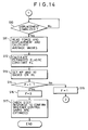
- the control section 8 carries out the processing for control system changeover (step S1).
- the control system changeover means 14 shown in Fig. 3 is caused to perform a changeover action, thereby selecting one of the controllers 17a and 17b, e.g., the controller 17a of the force control system.
- a time elapse vs. gain characteristic for gain adjustment (corresponding to the slanted portion of the dotted line C in Fig. 4) is set as shown in Fig. 9 (step S2), and a target force changing pattern for gain adjustment is set to be equal to a ramp hold waveform which is shown in Fig. 4 by a combination of the solid line D and the two-dotted chain line E (step S3).
- a force control is started which is carried out in accordance with the time elapse vs. gain characteristic and the target force changing pattern (step S5).
- step S6 Based on the actual displacement of the test piece S detected by the displacement gauge 6, a determination is made as to whether or not a minimum displacement which is measurable by the displacement gauge 6 is detected (step S6). If the minimum test piece displacement is detected (the time point of t1 shown in Fig. 4), the proportional gain and the target force at the time point of t1 are kept unchanged, as shown by the dotted line C and the solid line F in Fig. 4 (step S7). As a result, the actual force applied to the test piece S1 at the time point of t1 is kept substantially unchanged. Next, a determination is made as to whether or not the predetermined time period of T2 for stabilizing the test piece displacement has elapsed from the time point of t1 (step S8). If the time period of T2 has not elapsed, the control flow returns to step S7 where the proportional gain and the target force are maintained, and the actual displacement of the test piece S detected by the displacement gauge 6 is read by the controller 17a.
- step S8 If it is determined at step S8 that the time period of T2 has elapsed from the time point of t1 at which the minimum displacement was detected, a determination is made based on the tendency of a change in the actual test piece displacement as to whether or not the actual displacement of the test piece S is stabilized (step S10 in Fig. 14). Ordinarily, the actual test piece displacement is stabilized when the time period of T2 has elapsed. However, if it is determined at step S10 that the actual test piece displacement has not been stabilized as yet, the controller waits for the test piece displacement being stabilized.
- step S10 If it is determined at step S10 that the actual displacement of the test piece S has been stabilized, the output of the load cell 1 indicative of the actual force applied to the test piece S is periodically read a multi-number of times, e.g., 200 times, and the output of the displacement gauge 6 indicative of the actual displacement of the test piece is periodically read a multi-number of times, e.g., 200 times. Then, an average value of the detected actual forces and an average of the detected actual displacements are calculated (step S11).
- an estimated elastic constant KL of the test piece S is calculated based on the average actual force and the average actual displacement (step S12), and the optimum proportional gain KP and optimum integral gain KI for the force control mode, suited to the elastic constant, are determined based on the estimated elastic constant KL and set in the controller 17a of the force control system (step S13).
- the control gain setting processing for the displacement control system is carried out as in the case of the force control system. More specifically, at step S2, the time elapse vs. gain characteristic shown in Fig. 10 is set, and, at step S3, a target displacement changing pattern (not shown) similar to the target force changing pattern of Fig. 4 is set.
- the target displacement has its initial value set to be equal to the sum of the actual test piece displacement observed at the completion of the control gain setting for the force control system and an initial value of the target displacement determined by the target displacement changing pattern.
- step S4 the initial control gain for the displacement control system is set, and at step S5, the displacement control is started. If it is determined at step S6 that a minimum displacement of the test piece S (here, a displacement equal to the sum of the actual test piece displacement observed at the completion of the control gain setting for the force control system and the minimum displacement) is detected, both the control gain and the target displacement observed when the minimum displacement is detected are kept unchanged for a predetermined time period, at steps S7 and S8.
- a minimum displacement of the test piece S here, a displacement equal to the sum of the actual test piece displacement observed at the completion of the control gain setting for the force control system and the minimum displacement
- step S10 After elapse of the predetermined time period, it is determined at step S10 that the actual test piece displacement is stabilized, the average values of both the actual force applied to and the actual displacement of the test piece S are calculated at step S11, and the elastic constant of the test piece is estimated based on the average actual force and the average actual displacement at step S12. Then, at step S13, the proportional gain KP and the integral gain KI, suited to the estimated elastic constant, for the displacement control mode are set in the controller 17b of the displacement control system.
- step S14 Since the result of determination at step S14 becomes affirmative, the flag F is reset to a value of 0 at step S16, and the step response or the like is determined to confirm whether or not the control gains are optimized at step S17, whereupon the control gain setting processing is completed. More specifically, at step S17, the step response in the force control system and the step response in the displacement control system are checked, while setting the step input of target force and the step input of target displacement so as not to apply an excessive load to the test piece S and carrying out the control system changeover processing where required.
- an optimum control gain suited to mechanical properties of the test piece S can be easily set within a short period of time, as explained above, even if mechanical properties of the test piece such as stiffness (elastic constant) are unknown.
- the elastic constant KL can be determined without applying an excessive load to the test piece S, so that an optimum control gain setting may be achieved under a simplified control algorithm.
- the elastic constant KL is estimated based on sampled data in respect of the force and displacement of the test piece, obtained by sampling them a multi-number of times after the displacement of the test piece applied with a slight load is stabilized, the estimation can be made with a sufficiently high accuracy.
- the control gain best suited to the control system is determined by inverse operation based on the estimated elastic constant and is set therein, the automatic control gain setting can be made efficiently.
- the automatic control gain setting processing of the present embodiment can be modified variously.
- the time elapse vs. gain characteristic or the target load changing pattern, especially, a maximum applied force in this pattern may be set by taking account of the type of material testing.
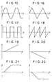
- the force applied to the test piece S is caused to vary in the form of triangular wave as shown in Fig. 16, and in the case of creep-relaxation test, the force is caused to increase in the form of ramp wave and is then caused to be kept unchanged, as shown in Fig. 21. Further, in the case of tensile or compression test, the force or displacement is caused to increase at a fixed slope, as shown in Fig. 19 or 20.
- the elastic constant may be estimated based on the relationship between the displacement and force detected after the test piece displacement is stabilized in a condition that the test piece is applied with the force which corresponds to 30 to 50% of the maximum value of the target force to be applied to the test piece S in material testing.
- the detected displacement can be greatly affected by noise.
- the periodically detected displacements may be subject to filtering based on moving average method, and it may be determined that a significant displacement is generated in the test piece attributable to the application of load (force), if a predetermined displacement is successively detected a multi-number of times.
- an approximate optimum control gain may be determined in accordance with an approximation formula determined by the small quantity of data, on the basis of an estimated elastic constant determined by an average force and an average displacement.
- control gain for a distortion control system can be automatically determined, while carrying out a distortion control with use of distortion generated in the test piece S as a controlled variable.
- the testing machine has a function of correcting a predetermined control gain for the feedback control effected during the material testing, in accordance with a mechanical change (stiffness change) generated in the test piece S, to thereby optimize the feedback control gain during the material testing.
- the correcting function is achieved by measurement means for periodically measuring the actual force applied to and the actual displacement generated in the test piece S, estimation means for estimating the elastic constant of the test piece on the basis of the relationship between the measured force and the measured displacement, and correction means for correcting and optimizing the control gain having been set in accordance with the estimated elastic constant.
- material testing in respect of the test piece S is started with use of the optimally initialized control gain. More specifically, fatigue test, creep test, relaxation test, tensile test or compression test in respect of the test piece S is selectively carried out by variably controlling the target load for the control system with use of a signal generator (shown by reference numeral 8d in Fig. 1).
- a testing waveform which periodically changes in a specific pattern, such as sinusoidal wave, triangular wave, rectangular wave or ramp wave shown in Figs. 15 to 18, is generated by the signal generator 8d and is supplied, as the control objective value, to the controller 8c of the control section 8.
- the target value of the load to be applied to the test piece S periodically changes, so that the fatigue test is carried out.
- a ramp wave shown in Fig. 19 or 20 is given as the target value.
- a ramp-hold wave shown in Fig. 21 or 22 is given as the target value for creep-relaxation compression/tensile test.
- the control gain set for the control section 8 (more generally, for the servo control system) sometimes deviates from it optimum value if mechanical properties (stiffness) of the test piece S change as the material testing proceeds.
- the deviation of the control gain from the optimum value causes the load actually applied to the test piece to change, thereby lowering the testing accuracy.
- the load (force) periodically changes in its amplitude (width) during the material testing
- the changing width of the actual load (actual force) applied to the test piece and the level of the actual load (actual average force) sometimes vary, thereby causing the test condition to vary. This naturally causes an error in the material testing and hence lowers the accuracy and reliability of the material testing.
- a change in the elastic constant KL of the test piece S is monitored during the course of fatigue test carried out with use of a predetermined control gain which was set in the servo control system, by measuring, at intervals of a predetermined cycle, the load applied to and the displacement generated in the test piece S and by periodically estimating the elastic constant KL based on the relationship between the detected force and displacement. If a change in the elastic constant KL of the test piece S is detected, an optimum control gain suited to a new elastic constant KL of the test piece is determined by searching the aforementioned table, for instance, and the control gain previously set in the servo control system is corrected so as to be optimized.
- a control gain correction routine shown in Fig. 23 is executed by the control section 8 during the material testing.
- the force applied to the test piece S and the displacement generated by the applied force in the test piece S are measured at intervals of a cycle which is sufficiently shorter than the cycle at intervals of which the force applied to the test piece S periodically varies, e.g., measured at intervals of a cycle (100 ⁇ sec, for instance) at which the control section 8 carries out its operation (step S101). Then, a determination is made as to whether or not a predetermined number of data samples in respect of each of the force and the displacement is attained (step S102). If it is determined that a sufficient number of data samples is attained, an average force and an average displacement are determined, and the elastic constant KL of the test piece S is estimated based on these average values (step S103).
- the difference ⁇ KL between the estimated elastic constant KL and an elastic constant corresponding to the control gain currently set in the servo control system i.e., a change in elastic constant caused by a change in the load state of the test piece S is determined (step S104).
- the threshold value serves to prevent an excessively frequent correction of control gain which would be otherwise corrected even if the elastic constant slightly changes.
- the thus determined optimum control gain is set in the servo control system, to thereby correct the control gain previously set therein (step S107).
- the control gain correction is carried out at timing which is synchronized with the cycle at which the target force for the servo control system periodically varies.
- the optimum control gain suited to the changed elastic constant is determined and is set in the servo control system, whereby the control gain set therein is optimally corrected.
- the control gain is optimally corrected in accordance with the elastic constant of the test piece S estimated during the course of the material testing, if the control gain deviates from its optimum value as the mechanical properties (elastic constant KL) of the test piece S change while the material testing proceeds after the start of the testing which was started in a condition that an optimum control gain was set by means of the aforementioned automatic control gain setting.
- control gain can be optimized in accordance with the elastic constant of the test piece S estimated during the course of the testing even if an error between the optimum control gain and the control gain initially set in a trial and error manner is considerably large.
- control gain optimizing function the control gain for the servo control system is always optimized, so that the material testing can be carried out with the operation of the control system stabilized, thereby highly improving the testing accuracy. Furthermore, the control gain is optimally corrected only if the elastic constant KL of the test piece S changes beyond the threshold value, i.e., only if a significant error is found in the control gain setting. Thus, the control gain correction is made without being extremely sensitive to a slight change in the elastic constant of the test piece S. This makes it possible to optimize the control gain to thereby keep the control system stabilized, whereby the material testing can be made highly accurately.
- control gain correction of the present embodiment can be modified in various manners.
- optimum control gains corresponding to elastic constants KL of various test pieces are stored in advance in the table and the optimum control gain suited to the estimated elastic constant is determined by searching the table.
- the optimum control gain suited to the elastic constant KL may be derived by means of approximate calculation with use of an arbitrary-degree polynomial approximate equation given in advance and showing the optimum control gain as a function of elastic constant.
- the initial value of the control gain may be set by changing, in a trial and error manner, the control gain once set by taking account of an experientially estimated elastic constant.
- the initial control gain may be set based on the already-known data in respect of the test piece S, such as elastic constant data.
- the level or amplitude of the testing waveform may be corrected in the control gain correction.
- the testing machine of this embodiment is designed to select either the force control system 12 or the displacement control system 13 by means of the control system changeover means 14, as shown in Fig. 3, to thereby feedback-control the servo system 11 in either force control mode or displacement control mode.
- the feedback control for the servo system 11 is carried out in the form of PI control where the differential term in PID control is set to zero.
- the differential control gain may be set to carry out PID control.
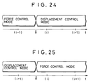
- the changeover of control system is performed when instructions are give by an operator in the course of material testing in respect of the test piece S. For instance, a shift is made from the force control mode where the actual force applied to the test piece is controlled to the target force to the displacement control mode where the actual displacement of the test piece S is controlled to the target displacement, as shown in Fig. 24. Conversely, a shift is made from the displacement control mode to the force control mode, as shown in Fig. 25.
- the control output value U with which the operation of the servo system 11 is controlled greatly varies at the time of mode changeover due to the difference of control gain between the force control system 12 and the displacement control system 13.
- the load applied to the test piece S abruptly changes, so that an undesired shock may be applied to the test piece.
- the load applied to the test piece is released once, e.g., by resetting the load to zero.
- the material testing machine of this embodiment achieves the control mode changeover in a way mentioned below, without causing a shock to the test piece.
- the changeover of control mode is executed in response to a request for changeover shown by triangular marks in Figs. 24 and 25.
- the control output value given to the servo system 11 just before the changeover and that just after the changeover are equal to each other, no substantial change occurs in operational state of the servo system 11, so that the load applied to the test piece S does not change at the time of changeover of control mode.
- the changeover of control system can be made without giving a shock to the test piece, if the control output value U K (i-1) given from the controller 17a of the force control system 12 at the control timing [i-1] just before the control system changeover is equal to the control output value U H (i) given from the controller 17b of the displacement control system 13 to the servo system 11 at the control timing [i] just after the control system changeover.
- the changeover from the displacement control mode to the force control mode can be made without causing a shock, if the control output value U H (i-1) given from the controller 17b of the displacement control system 13 to the servo system 11 just before the mode changeover is equal to the control output value U K (i) given by the controller 17a of the force control system 12 to the servo system 11 just after the mode changeover.
- the initial setting of a value of the integral term (the integral value ⁇ K or ⁇ H of error) for the post-changeover control system is carried out based on the control output value U(i-1) given to the servo system 11 at the control timing [i-1] just before the control system changeover, to eliminate the difference between the control output values U K and U H , attributable to control gain difference, which would be otherwise observed just before and after the control system is changed over.
- control output value U H (i) U H (i)
- the target displacement R H (i) just after the mode changeover is preferably set to a value which is equal to the displacement H(i) which is in turn substantially the same, in general, to the actual displacement H(i-1) just before the mode changeover.
- the proportional control gain P H and the integral control gain I H are determined in dependence on the elastic constant of the test piece S.
- the integral value ⁇ H of error in the integral term I H ⁇ H in the right side of formula (2a) can be set arbitrarily. Therefore, the relationship shown in formula (3) can be satisfied by setting the integral value ⁇ H of error to an appropriate value in the initial setting.
- the control system changeover means 14 initially sets the thus calculated value as the integral value employed for control calculation which is shown in formula (2) and which is performed by the controller 17b.
- the integral value ⁇ H calculated in accordance with formula (4) based on the control output value U K (i-1) given to the servo system 11 just before the control mode changeover represents a history of the displacement of the test piece S caused by the force applied thereto.
- control system changeover means 14 which has the function of making the control output values U K and U H , respectively supplied from the controller 17a of the force control system 12 and the controller 17b of the displacement control system 13 before and after the changeover of control system, equal from each other by the initial setting of the integral values ⁇ K and ⁇ H, extra work of temporarily terminating the operation of the servo system 11 to thereby reset the load applied to the test piece S to zero becomes unnecessary, whereby the changeover of control mode can be made easily, as needed.
- the changeover of control mode can be carried out in a condition that the control output value U supplied to the servo system 11 is kept unchanged, and therefore, an undesired shock never be applied to the test piece S.
- control mode changeover of the present embodiment may be modified variously.
- the mode changeover can be made with ease. That is, by setting the initial value of the target force or the target displacement just after the mode changeover to be equal to the actual force or the actual displacement detected just before the mode changeover, the error ⁇ e just after the mode changeover can be set to a value of zero. By doing this, the control calculation upon mode changeover can be simplified.
- the initial setting of integral value ⁇ H or ⁇ K may be made only if the control gain difference between the force control system and the displacement control system is large enough to produce a large change in the control output value at the time of mode changeover. More specifically, such initial setting may be made only if it is expected in an estimation based on the elastic constant of the test piece S that a change greater than a threshold value will occur in the control output value at the time of mode changeover. Further, the initial setting of integral value ⁇ H or ⁇ K may be selectively performed depending on whether or not the ratio between the target displacement in the displacement control system and the target displacement determined by conversion of the target force in the force control system to target displacement exceeds a threshold value.
Landscapes
- Physics & Mathematics (AREA)
- General Physics & Mathematics (AREA)
- Engineering & Computer Science (AREA)
- Automation & Control Theory (AREA)
- General Health & Medical Sciences (AREA)
- Biochemistry (AREA)
- Analytical Chemistry (AREA)
- Chemical & Material Sciences (AREA)
- Immunology (AREA)
- Pathology (AREA)
- Life Sciences & Earth Sciences (AREA)
- Health & Medical Sciences (AREA)
- Human Computer Interaction (AREA)
- Manufacturing & Machinery (AREA)
- Investigating Strength Of Materials By Application Of Mechanical Stress (AREA)
Abstract
Description
Claims (10)
- A material testing machine for measuring a mechanical property of a test piece (S) based on a load given to the test piece and a mechanical change generated in the test piece, while feedback-controlling an operation of a servo system (11) including a hydraulic actuator (3) which gives the load to the test piece by means of a controller (8) such that actual load applied to the test piece coincides with target load, comprising:gain setting means (S2) for setting the control gain for the feedback control performed during material testing;estimating means (S12, S103) for estimating a mechanical property of the test piece based on an actual load and a mechanical change in the test piece which are periodically detected during the material testing performed while carrying out the feedback control; andgain correcting means (S107) for correcting the control gain set by said gain setting means (S2) in accordance with the estimated mechanical property.
- The material testing machine according to claim 1, wherein said estimating means (S103) estimates stiffness of the test piece based on the actual load and the actual displacement of the test piece which are periodically detected during the material testing.
- The material testing machine according to claim 1, wherein, prior to the material testing, initial setting (Figs. 13 and 14) is made to set the initial value of the control gain for the feedback control performed during the material testing;said initial setting includes giving a load to the test piece, while performing a feedback control similar to the feedback control performed during the material testing, detecting the actual load of and the mechanical change in the test piece, and estimating the mechanical property of the test piece;said gain setting means (S2) causes the control gain to gradually increase from a minimum value of the control gain during the initial setting;said gain correcting means (S107) corrects the control gain to thereby set the initial value of the control gain, based on the estimated mechanical property of the test piece, the estimated mechanical property being determined by said estimating means based on the actual load applied to and the mechanical change generated in the test piece which are observed when a mechanical change in the test piece is detected during the initial setting; andthe material testing is started after the initial value of the control gain is set.
- The material testing machine according to claim 1, wherein said gain correcting means (S107) corrects the control gain set by said gain setting means to coincide with the control gain which corresponds to the estimated mechanical property determined by said estimating means (S103), by searching a table in which the control gain for every type of test piece is set in advance as a function of mechanical property of test piece.
- The material testing machine according to claim 1, further comprising:load maintaining means (S7) for maintaining load observed at a time (t1) when a minute change in the test piece is detected while applying a gradually increasing load prior to material testing; andinitial gain setting means (S13) for setting an initial value of the control gain (KP, KI) for the feedback control in accordance with the estimated mechanical property of the test piece;
wherein said estimating means (S12) estimates a mechanical property (KL) of the test piece based on actual load and a mechanical change of the test piece respectively detected after a displacement of the test piece is stabilized while the load observed when the minute change in the test piece was detected is maintained; andsaid initial gain setting means (S13) sets an initial value of the control gain (KP, KI) in accordance with the mechanical property of the test piece estimated by said estimating means while the load is maintained. - The material testing machine according to claim 5, wherein said initial gain setting means (S13) sets an initial value of a control gain for the controller (8) in accordance with the estimated mechanical property of the test piece determined by said estimating means (S12).
- The material testing machine according to claim 5, wherein said initial setting means (S13) sets the control gain (KP) at a minimum value of the control gain when giving the load to the test piece is started prior to material testing, and thereafter the control gain is gradually increased with elapse of time; andthe minute change in the test piece is detected when a mechanical change in the test piece beyond detecting resolution of a detector (1) is detected.
- The material testing machine according to claim 5, wherein said initial gain setting means (S13) searches a table (Fig. 7) in which the control gain is stored beforehand as a function of the mechanical property of the test piece, to thereby set the initial value of the control gain (KP, KI) based on the mechanical property (KL) estimated by said estimating means (S12).
- The material testing machine according to claim 1, further comprising:a force control system (12) including a controller (17a) for feedback-controlling the operation of the servo system based on an actual force applied to the test piece, the actual force serving as a controlled variable in the feedback control;a displacement control system (13) including a controller (17b) for feedback-controlling the operation of the servo system based on an actual displacement of the test piece, the actual displacement serving as a controlled variable in the feedback control; andcontrol system changeover means (14) for selectively operating either said force control system or said displacement control system, said control system changeover means making initial setting of a control output value (UH or UK) to be supplied from the controller in the post-changeover control system, based on a control output value (UK or UH) supplied from the controller in the pre-changeover control system to the servo system just before the changeover, and then making the control system changeover.
- The material testing machine according to claim 9, wherein the controller (17a) of the force control system determines the control output value UK to be supplied to the servo system in accordance with a formula given by:the controller (17b) of the displacement control system determines the control output value UH to be supplied to the servo system in accordance with a formula given by:said control system changeover mean (14) determines, based on the control output value UK or UH given to the servo system just before the control system changeover, the integral ΣH or ΣK of the error between the controlled variable initially set in the post-changeover control system and a control objective value in accordance with formulas, given by:
Applications Claiming Priority (9)
| Application Number | Priority Date | Filing Date | Title |
|---|---|---|---|
| JP218547/97 | 1997-08-13 | ||
| JP218549/97 | 1997-08-13 | ||
| JP21854997A JP3340055B2 (en) | 1997-08-13 | 1997-08-13 | Material testing machine |
| JP21854797A JP3340054B2 (en) | 1997-08-13 | 1997-08-13 | Material testing machine |
| JP21854897 | 1997-08-13 | ||
| JP21854797 | 1997-08-13 | ||
| JP21854997 | 1997-08-13 | ||
| JP218548/97 | 1997-08-13 | ||
| JP21854897A JP3368182B2 (en) | 1997-08-13 | 1997-08-13 | Material testing machine |
Publications (2)
| Publication Number | Publication Date |
|---|---|
| EP0897110A2 true EP0897110A2 (en) | 1999-02-17 |
| EP0897110A3 EP0897110A3 (en) | 2000-01-12 |
Family
ID=27330155
Family Applications (1)
| Application Number | Title | Priority Date | Filing Date |
|---|---|---|---|
| EP98115079A Withdrawn EP0897110A3 (en) | 1997-08-13 | 1998-08-11 | Material testing machine |
Country Status (3)
| Country | Link |
|---|---|
| US (1) | US6205863B1 (en) |
| EP (1) | EP0897110A3 (en) |
| KR (1) | KR100307270B1 (en) |
Cited By (11)
| Publication number | Priority date | Publication date | Assignee | Title |
|---|---|---|---|---|
| WO2008023226A2 (en) | 2006-08-21 | 2008-02-28 | Illinois Tool Works Inc. | Adaptive control of materials testing machine with tuning of initial control parameters |
| EP1902793A3 (en) * | 2006-09-20 | 2008-09-17 | Fanuc Ltd | Method for changing force gain in a die cushion control and die cushion control apparatus |
| EP1726376A3 (en) * | 2005-05-24 | 2009-07-08 | Fanuc Ltd | Controller for die cushion mechanism |
| GB2467184A (en) * | 2009-01-27 | 2010-07-28 | Illinois Tool Works | Load testing apparatus |
| CN101819112A (en) * | 2010-04-29 | 2010-09-01 | 十堰达峰软轴有限公司 | Device for testing stiffness of sheath of guy cable |
| CN103038048A (en) * | 2011-08-01 | 2013-04-10 | 三菱电机株式会社 | Control device and control method for injection molding machine |
| EP1845427A3 (en) * | 2006-03-07 | 2013-05-15 | Fanuc Corporation | Controller |
| US9270155B2 (en) | 2012-05-20 | 2016-02-23 | Mts Systems Corporation | Linear actuator assembly |
| CN109212967A (en) * | 2018-08-22 | 2019-01-15 | 浙江大学 | A kind of online track smoothing switching method of hydraulic material testing machine control model |
| CN112414842A (en) * | 2020-10-21 | 2021-02-26 | 中国石油大学(北京) | Rock rigidity determination method and device |
| US20210096048A1 (en) * | 2018-10-29 | 2021-04-01 | Shimadzu Corporation | Material testing machine |
Families Citing this family (12)
| Publication number | Priority date | Publication date | Assignee | Title |
|---|---|---|---|---|
| JP4851660B2 (en) * | 2001-05-31 | 2012-01-11 | 学校法人日本大学 | Universal material testing method and apparatus |
| JP2003106967A (en) * | 2001-09-28 | 2003-04-09 | Shimadzu Corp | Hydraulic-servo type material testing machine |
| EP1518101A4 (en) * | 2002-07-03 | 2008-03-19 | Midwest Research Inst | Resonance test system |
| US7437201B2 (en) * | 2003-01-14 | 2008-10-14 | Cullen Christopher P | Electric motor controller |
| US8766811B2 (en) | 2011-01-21 | 2014-07-01 | Nike, Inc. | Compression testing device for testing materials automatically |
| US9506782B2 (en) * | 2013-04-24 | 2016-11-29 | Bose Corporation | Apparatus and method for applying a load to a material |
| JP6477969B2 (en) * | 2016-02-24 | 2019-03-06 | 株式会社島津製作所 | Measuring device and material testing machine |
| JP6209635B2 (en) * | 2016-03-15 | 2017-10-04 | 日新製鋼株式会社 | Strength test method, strength test facility and virtual strength test program for metal roofing materials |
| US10545464B2 (en) * | 2016-12-01 | 2020-01-28 | The Boeing Company | Control system having variable gain feed forward (VGFF) control |
| CN108709807B (en) * | 2018-07-16 | 2023-10-10 | 江苏省特种设备安全监督检验研究院 | Open variable stroke tensile machine |
| US11906475B2 (en) * | 2018-12-21 | 2024-02-20 | Shimadzu Corporation | Material testing machine and method for controlling material testing machine |
| KR20250049834A (en) * | 2023-10-05 | 2025-04-14 | 삼성에스디아이 주식회사 | device and method of measuring pressure density of powder material for all-solid rechargeable battery |
Family Cites Families (8)
| Publication number | Priority date | Publication date | Assignee | Title |
|---|---|---|---|---|
| US3664179A (en) * | 1970-05-11 | 1972-05-23 | Gilmore Ind Inc | Apparatus and method for controlling a resonant testing machine |
| US4171644A (en) * | 1978-02-28 | 1979-10-23 | The United States Of America As Represented By The United States Department Of Energy | Means for ultrasonic testing when material properties vary |
| US4235114A (en) * | 1979-04-02 | 1980-11-25 | Ledex, Inc. | Material testing device |
| US4802367A (en) * | 1986-12-09 | 1989-02-07 | Mts Systems Corporation | Tensile test controller |
| GB8714182D0 (en) * | 1987-06-17 | 1987-07-22 | Northern Eng Ind | Testing materials |
| JP2773355B2 (en) * | 1990-02-27 | 1998-07-09 | 株式会社島津製作所 | Control device for material testing machine |
| GB9319788D0 (en) * | 1993-09-24 | 1993-11-10 | Instron Ltd | Structure testing machine |
| JP3570056B2 (en) * | 1996-01-26 | 2004-09-29 | 株式会社島津製作所 | Material testing machine |
-
1998
- 1998-08-11 EP EP98115079A patent/EP0897110A3/en not_active Withdrawn
- 1998-08-11 KR KR1019980032556A patent/KR100307270B1/en not_active Expired - Fee Related
- 1998-08-13 US US09/133,838 patent/US6205863B1/en not_active Expired - Fee Related
Cited By (25)
| Publication number | Priority date | Publication date | Assignee | Title |
|---|---|---|---|---|
| EP1726376A3 (en) * | 2005-05-24 | 2009-07-08 | Fanuc Ltd | Controller for die cushion mechanism |
| US7619384B2 (en) | 2005-05-24 | 2009-11-17 | Fanuc Ltd | Controller for die cushion mechanism |
| EP2388081A1 (en) * | 2005-05-24 | 2011-11-23 | Fanuc Corporation | Controller for die cushion mechanism |
| EP1845427A3 (en) * | 2006-03-07 | 2013-05-15 | Fanuc Corporation | Controller |
| US8151650B2 (en) | 2006-08-21 | 2012-04-10 | Illinois Tool Works Inc. | Tuning of materials testing machine |
| WO2008023226A3 (en) * | 2006-08-21 | 2008-06-12 | Illinois Tool Works | Adaptive control of materials testing machine with tuning of initial control parameters |
| CN101506639B (en) * | 2006-08-21 | 2013-04-10 | 伊利诺斯工具制品有限公司 | Method of operating a materials tester to test specimens and tester |
| WO2008023226A2 (en) | 2006-08-21 | 2008-02-28 | Illinois Tool Works Inc. | Adaptive control of materials testing machine with tuning of initial control parameters |
| EP1902793A3 (en) * | 2006-09-20 | 2008-09-17 | Fanuc Ltd | Method for changing force gain in a die cushion control and die cushion control apparatus |
| US7757526B2 (en) | 2006-09-20 | 2010-07-20 | Fanuc Ltd | Method for changing force control gain and die cushion control apparatus |
| EP2522980A2 (en) | 2009-01-27 | 2012-11-14 | Illinois Tool Works, Inc. | Apparatus, controller and method for adaptive control of an electromagnetic actuator |
| EP2389572B1 (en) * | 2009-01-27 | 2016-12-07 | Illinois Tool Works Inc. | Apparatus, controller and method for adaptive control of an electromagnetic actuator |
| WO2010088193A2 (en) | 2009-01-27 | 2010-08-05 | Illinois Tool Works Inc. | Apparatus, controller and method for adaptive control of an electromagnetic actuator |
| GB2467184A (en) * | 2009-01-27 | 2010-07-28 | Illinois Tool Works | Load testing apparatus |
| CN101819112A (en) * | 2010-04-29 | 2010-09-01 | 十堰达峰软轴有限公司 | Device for testing stiffness of sheath of guy cable |
| CN101819112B (en) * | 2010-04-29 | 2012-08-22 | 十堰达峰软轴有限公司 | Device for testing stiffness of sheath of guy cable |
| CN103038048A (en) * | 2011-08-01 | 2013-04-10 | 三菱电机株式会社 | Control device and control method for injection molding machine |
| CN103038048B (en) * | 2011-08-01 | 2015-06-17 | 三菱电机株式会社 | Control device and control method for injection molding machine |
| US9270155B2 (en) | 2012-05-20 | 2016-02-23 | Mts Systems Corporation | Linear actuator assembly |
| CN109212967A (en) * | 2018-08-22 | 2019-01-15 | 浙江大学 | A kind of online track smoothing switching method of hydraulic material testing machine control model |
| CN109212967B (en) * | 2018-08-22 | 2020-11-20 | 浙江大学 | An online tracking smooth switching method for the control mode of a hydraulic material testing machine |
| US20210096048A1 (en) * | 2018-10-29 | 2021-04-01 | Shimadzu Corporation | Material testing machine |
| US11740165B2 (en) * | 2018-10-29 | 2023-08-29 | Shimadzu Corporation | Material testing machine |
| CN112414842A (en) * | 2020-10-21 | 2021-02-26 | 中国石油大学(北京) | Rock rigidity determination method and device |
| CN112414842B (en) * | 2020-10-21 | 2022-02-08 | 中国石油大学(北京) | Rock rigidity determination method and device |
Also Published As
| Publication number | Publication date |
|---|---|
| US6205863B1 (en) | 2001-03-27 |
| KR19990023515A (en) | 1999-03-25 |
| EP0897110A3 (en) | 2000-01-12 |
| KR100307270B1 (en) | 2001-12-17 |
Similar Documents
| Publication | Publication Date | Title |
|---|---|---|
| US6205863B1 (en) | Material testing machine having a control system for feedback-controlling the operation of a servo system | |
| US6192299B1 (en) | Method of measuring operation characteristic of proportional electromagnetic control valve, method of controlling operation of hydraulic cylinder, and method of modifying operation characteristic of proportional electromagnetic control valve | |
| RU2528222C2 (en) | Calibration of valves | |
| KR950009911B1 (en) | Thickness control system for rolling mill | |
| US5952582A (en) | Test apparatus with control constant computing device | |
| US5494427A (en) | Pressure sensing device for injection molding machines | |
| KR100687310B1 (en) | Rolling method and rolling apparatus of metal sheet | |
| US20100045214A1 (en) | Shape memory alloy actuator system | |
| WO2008049796A1 (en) | Process and device for measuring and controlling structural deflections of a pressing-bending machine | |
| EP0897109B1 (en) | Material testing machine | |
| JPH1164193A (en) | Fatigue testing machine | |
| JP3570056B2 (en) | Material testing machine | |
| JP5353805B2 (en) | testing machine | |
| JPH1164191A (en) | Material testing machine | |
| EP1875982B1 (en) | Spot welding method and spot welding system | |
| JP2001075651A (en) | Valve positioner | |
| JP3368183B2 (en) | Material testing machine | |
| JP3608302B2 (en) | Fatigue testing machine | |
| JP3340055B2 (en) | Material testing machine | |
| JP3340056B2 (en) | Material testing machine | |
| JP3716976B2 (en) | Electro-hydraulic servo type material testing machine | |
| JP3526746B2 (en) | Material testing machine | |
| JP7079078B2 (en) | Control device | |
| KR100348060B1 (en) | Method for controlling thickness of front end part of steel plate in plate rolling process | |
| KR100786010B1 (en) | Dynamometer load automatic tracking P.ID control method |
Legal Events
| Date | Code | Title | Description |
|---|---|---|---|
| PUAI | Public reference made under article 153(3) epc to a published international application that has entered the european phase |
Free format text: ORIGINAL CODE: 0009012 |
|
| 17P | Request for examination filed |
Effective date: 19980903 |
|
| AK | Designated contracting states |
Kind code of ref document: A2 Designated state(s): DE FR GB |
|
| AX | Request for extension of the european patent |
Free format text: AL;LT;LV;MK;RO;SI |
|
| PUAL | Search report despatched |
Free format text: ORIGINAL CODE: 0009013 |
|
| AK | Designated contracting states |
Kind code of ref document: A3 Designated state(s): AT BE CH CY DE DK ES FI FR GB GR IE IT LI LU MC NL PT SE |
|
| AX | Request for extension of the european patent |
Free format text: AL;LT;LV;MK;RO;SI |
|
| RIC1 | Information provided on ipc code assigned before grant |
Free format text: 7G 01N 3/10 A, 7G 05D 15/01 B, 7G 05D 17/02 B, 7G 05D 3/00 B, 7G 05B 13/04 B |
|
| AKX | Designation fees paid |
Free format text: GB |
|
| RBV | Designated contracting states (corrected) |
Designated state(s): DE FR GB |
|
| REG | Reference to a national code |
Ref country code: DE Ref legal event code: 8566 |
|
| 17Q | First examination report despatched |
Effective date: 20070108 |
|
| STAA | Information on the status of an ep patent application or granted ep patent |
Free format text: STATUS: THE APPLICATION IS DEEMED TO BE WITHDRAWN |
|
| 18D | Application deemed to be withdrawn |
Effective date: 20090303 |