EP0897103B2 - Aircraft containing an apparatus for determining the quantity of fluid within a tank - Google Patents
Aircraft containing an apparatus for determining the quantity of fluid within a tank Download PDFInfo
- Publication number
- EP0897103B2 EP0897103B2 EP98202464A EP98202464A EP0897103B2 EP 0897103 B2 EP0897103 B2 EP 0897103B2 EP 98202464 A EP98202464 A EP 98202464A EP 98202464 A EP98202464 A EP 98202464A EP 0897103 B2 EP0897103 B2 EP 0897103B2
- Authority
- EP
- European Patent Office
- Prior art keywords
- tank
- load cell
- aircraft
- fluid
- central processing
- Prior art date
- Legal status (The legal status is an assumption and is not a legal conclusion. Google has not performed a legal analysis and makes no representation as to the accuracy of the status listed.)
- Expired - Lifetime
Links
Images
Classifications
-
- G—PHYSICS
- G01—MEASURING; TESTING
- G01F—MEASURING VOLUME, VOLUME FLOW, MASS FLOW OR LIQUID LEVEL; METERING BY VOLUME
- G01F23/00—Indicating or measuring liquid level or level of fluent solid material, e.g. indicating in terms of volume or indicating by means of an alarm
- G01F23/20—Indicating or measuring liquid level or level of fluent solid material, e.g. indicating in terms of volume or indicating by means of an alarm by measurement of weight, e.g. to determine the level of stored liquefied gas
-
- G—PHYSICS
- G01—MEASURING; TESTING
- G01G—WEIGHING
- G01G1/00—Weighing apparatus involving the use of a counterweight or other counterbalancing mass
- G01G1/18—Balances involving the use of a pivoted beam, i.e. beam balances
-
- G—PHYSICS
- G01—MEASURING; TESTING
- G01G—WEIGHING
- G01G19/00—Weighing apparatus or methods adapted for special purposes not provided for in the preceding groups
- G01G19/08—Weighing apparatus or methods adapted for special purposes not provided for in the preceding groups for incorporation in vehicles
Definitions
- the present invention relates to an aircraft comprising an apparatus for measuring a quantity of fluid within a tank, and, more particularly, to an aircraft comprising an apparatus for measuring the quantity and level of fluid in the tank by measuring the weight of the tank.
- the present invention is directed toward a system for measuring the quantity of fluid in a tank located within an aircraft.
- Fig. 1 shows a prior art measurement system for measuring fluid 112 within a tank 114.
- the tank 114 may be a waste holding tank or a fuel tank.
- a plurality of strain-gauge load cells 116 which provide analog voltage outputs that correspond proportionally to the load forces applied to cells 116, are positioned between the tank 114 and a common reference surface 118.
- the tank load cells 116 are positioned at all the mounting points for the tank 114, which typically totals four separate locations beneath the tank 114.
- the plurality of load cells provides for measuring and compensating for increased and/or decreased gravitational forces or inertial forces that may be exerted upon the fluid resulting from the movement of the aircraft.
- a reference strain-gauge load cell 124 is placed between a reference standard 126 of known weight and the common reference surface 118.
- the reference load cell 124 provides an analog voltage output in proportion to the load placed on the load cell 124 by the reference standard 126.
- the reference load cell 124 is also aligned to be sensitive to load forces generally parallel along an axis which is substantially normal to the common reference surface 118.
- a Central Processing Unit (CPU) 130 is coupled to receive the analog voltage output from the load cells 116 and the reference load cell 124, and it converts these analog signals into output information on the level of the fluid 112 in the tank 114.
- An averaging device 132 electrically averages out short term transients appearing in the analog voltage output signals from the load cells 116.
- the CPU 130 invokes a program that adds the read-outs from the plurality of the load cells 116, and then divides this amount by the G-force, which is determined by the reference load cell 124.
- a read-out device 134 such as an analog dial, LCD or LED display, is operatively linked to the CPU 130 for displaying the level of the fluid 112 contained in the tank 114.
- the plurality of the load cells 116 are mounted along a plurality of points between the tank 116 and the reference surface 118.
- the requirement to process a plurality of signals from multiple load cells 116 and perform compensating operations based on the output of a specific reference load cell, such as the load cell 124, can increase the likelihood of errors and will increase maintenance costs, as well as increase CPU processing requirements. Accordingly, there is a need in the art for a fluid-level measuring system which is simple and has fewer parts requiring maintenance.
- DE-A1-37 37 658 discloses an apparatus for measuring the tank content of an operational liquid tank on a motor vehicle.
- the latter is mounted to pivot about a horizontal axis and engages, in the region of its other side, in a torque pick-up with a force-measuring element, of which the output signal is evaluated to determine the respective weight of the filled tank as a measure of the tank content.
- the present invention relates to an aircraft, comprising an apparatus for measuring the amount of liquid in a tank mounted within said aircraft, said apparatus comprising:
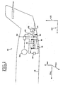
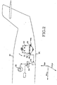
- Fig. 2 shows, in schematic diagram, an apparatus 20 for measuring the quantity of fluid in a tank 22 by measuring the weight of the tank 22 in a simple, easily maintainable manner.
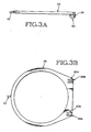
- the apparatus 20 includes a cantilevered tank-mount 24, shown in Figs. 3A and 3B , which is part of the tank 22 which is or mechanically coupled to the tank 22, and pivotally mounted at first and second pivot points, 26A and 26B, respectively.
- the pivot points 26A and 26B work like hinges to limit the tank 22 to rotational motion about a shared axis defined by a first and second aligned axis 40A and 40B of the two pivot points 26A and 26B, respectively.
- the tank-mount 24 also includes an extended end 42, positioned opposite the first and second pivot points 26A and 26B, that engages a single load cell 28, as shown in Fig. 2 .
- the single load cell 28 provides an analog voltage signal that directly corresponds to the static load forces applied by the extended end 42.
- the signal is processed by a filtering device 30, which is well known in the art, in electrical communication with the load cell 28.
- the apparatus 20 also includes a CPU 34 in electrical communication with the filtering device 30.
- the CPU 34 processes signals from the filter 30 and an inclinometer 32 and outputs a fluid level of the tank 22 on a display device 36.
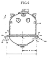
- Fig. 4 shows one embodiment of the tank 22 of the apparatus 20.
- the tank-mount 24 is fastened about the pivot points 26A and 26B which are rotatingly engaged via pins 27 in an orifice of first and second fixed structures 44A and 44B. This limits the movement of the tank 22 to rotation about the pins 27 which are aligned along the common X axis. Thus, only movement and transient forces along the path of rotation C can be detected by the load cell 28. All other influences are mechanically eliminated.
- the fixed structures 44A and 44B hold the tank 22 up at the pivot points 26A and 26B by applying a force F p away from the aircraft body 29, shown in Fig. 2 .
- the load cell 28 is structurally connected to a second fixed structure 46, which is preferably coupled to the aircraft body 29, thereby keeping the cell 28 in a fixed position relative to the extended end 42, which rests upon the load cell 28 in a static state.
- the use of a single load-cell 28, which is installed opposite to the pivot points 26A and 26B makes the load-cell 28 easy to install, replace, and maintain. Thus, a large cost savings may be realized by using the apparatus 20 instead of prior art devices.
- the tank 22 may contain sewage, and an easily maintainable system may reduce health hazards potentially caused by long term exposure to this type of environment. Further, the processing of a single signal is faster and requires a less complex processing means.
- a force F s is applied to the sensing load cell 28 by the extended end 42 and it is proportional to the weight of the tank 22.
- distances A and B are known values for the installation, the relationship between the force F s , measured by the sensing load cell 28, and the weight of the fluid in the tank can be easily calculated. Further, the weight of the fluid is linearly proportional to the volume of the fluid, which can be used to determine the fluid level or what percentage of the tank 22 is filled. Thus, by measuring the force F s at the load cell 28, the weight, quantity and level of the fluid within the tank 22 can be calculated.
- the CPU 34 outputs this level to the display 36.
- the CPU is electronically coupled to an inclinometer 32 which senses the change in the angle of attack of the airplane. This angle is then communicated to the CPU 34 which adjusts the relationship between total weight of fluid and force registered by the load cell 28 accordingly. This may be accomplished by a "look-up table" contained in the CPU which relates the force registered by the load cell 28 to the total weight of the fluid for each anticipated angle.
- the present invention provides a simple and easily maintainable apparatus for measuring the fluid level within an aircraft without the need of multiple load cell sensors or the need to process multiple signals.
Landscapes
- Physics & Mathematics (AREA)
- General Physics & Mathematics (AREA)
- Fluid Mechanics (AREA)
- Level Indicators Using A Float (AREA)
- Measurement Of Levels Of Liquids Or Fluent Solid Materials (AREA)
Description
- The present invention relates to an aircraft comprising an apparatus for measuring a quantity of fluid within a tank, and, more particularly, to an aircraft comprising an apparatus for measuring the quantity and level of fluid in the tank by measuring the weight of the tank.
- The present invention is directed toward a system for measuring the quantity of fluid in a tank located within an aircraft.
Fig. 1 shows a prior art measurement system for measuringfluid 112 within atank 114. Thetank 114 may be a waste holding tank or a fuel tank. - A plurality of strain-
gauge load cells 116, which provide analog voltage outputs that correspond proportionally to the load forces applied tocells 116, are positioned between thetank 114 and acommon reference surface 118. Thetank load cells 116 are positioned at all the mounting points for thetank 114, which typically totals four separate locations beneath thetank 114. - A system of this kind is disclosed in
US-A-5 133 212 . The plurality of load cells provides for measuring and compensating for increased and/or decreased gravitational forces or inertial forces that may be exerted upon the fluid resulting from the movement of the aircraft. - A reference strain-
gauge load cell 124 is placed between areference standard 126 of known weight and thecommon reference surface 118. Thereference load cell 124 provides an analog voltage output in proportion to the load placed on theload cell 124 by thereference standard 126. Thereference load cell 124 is also aligned to be sensitive to load forces generally parallel along an axis which is substantially normal to thecommon reference surface 118. - A Central Processing Unit (CPU) 130, is coupled to receive the analog voltage output from the
load cells 116 and thereference load cell 124, and it converts these analog signals into output information on the level of thefluid 112 in thetank 114. Anaveraging device 132 electrically averages out short term transients appearing in the analog voltage output signals from theload cells 116. TheCPU 130 invokes a program that adds the read-outs from the plurality of theload cells 116, and then divides this amount by the G-force, which is determined by thereference load cell 124. Finally, a read-outdevice 134, such as an analog dial, LCD or LED display, is operatively linked to theCPU 130 for displaying the level of thefluid 112 contained in thetank 114. - To properly measure the weight of the
tank 114, the plurality of theload cells 116 are mounted along a plurality of points between thetank 116 and thereference surface 118. The requirement to process a plurality of signals frommultiple load cells 116 and perform compensating operations based on the output of a specific reference load cell, such as theload cell 124, can increase the likelihood of errors and will increase maintenance costs, as well as increase CPU processing requirements. Accordingly, there is a need in the art for a fluid-level measuring system which is simple and has fewer parts requiring maintenance. -
DE-A1-37 37 658 discloses an apparatus for measuring the tank content of an operational liquid tank on a motor vehicle. To achieve a sufficiently accurate vindication of the content of a tank fixed to the motor vehicle, especially a fuel tank, the latter is mounted to pivot about a horizontal axis and engages, in the region of its other side, in a torque pick-up with a force-measuring element, of which the output signal is evaluated to determine the respective weight of the filled tank as a measure of the tank content. - The present invention relates to an aircraft, comprising an apparatus for measuring the amount of liquid in a tank mounted within said aircraft, said apparatus comprising:
- a tank-mount mechanically coupled to and surrounding said tank to prevent translational movement of said tank, said tank-mount being fastened about pivot points to a plurality of fixed structures mechanically coupled to the aircraft, such that movement of the tank is limited to rotation about a common axis going through orifices of said structures; said tank-mount having an extended end positioned on a side of said tank opposite to said plurality of pivot points, which extends outwardly from said tank;
- a load cell in contact with said extended end for providing a first signal proportional to a force Fs placed on said load cell by said extended end;
- a Central Processing Unit in electrical communication with said load cell, and which is arranged to process the first signal from said load cell and calculates the amount of the fluid in said tank based on the force Fs on said load cell, a distance A from the center of gravity said tank to the common axis, and a distance B from the common axis to where said extended end applies the load Fs to said load cell such that the actual weight FT of the tank and the fluid is calculated by the equation FT = (B/A) x (Fs); and
- an inclinometer electrically coupled to said Central Processing Unit, said inclinometer transmitting a second signal to said Central Processing Unit directly proportional to the angle of inclination of the airplane, wherein the Central Processing Unit is arranged to process the second signal and adjusts the relationship between the total weight of said tank and the force registered by the load cell accordingly.
- These and other features, aspects, and advantages of the present invention will become better understood with regard to the following descriptions, appended claims, and accompanying drawings where:
-
Fig. 1 shows a schematic diagram of a prior art apparatus for measuring the liquid level in a tank; -
Fig. 2 shows a schematic diagram of an apparatus for measuring the level of fluid in a tank according to the present invention; -
Fig. 3A shows a side view of a tank-mount of the apparatus for measuring the level of fluid in the tank; -
Fig. 3B shows a bottom view of the tank-mount; and -
Fig. 4 shows a side view of the tank and the pivoting tank-mount of the apparatus for measuring the quantity of fluid in the tank. - Referring to the drawings,
Fig. 2 shows, in schematic diagram, anapparatus 20 for measuring the quantity of fluid in atank 22 by measuring the weight of thetank 22 in a simple, easily maintainable manner. - The
apparatus 20 includes a cantilevered tank-mount 24, shown inFigs. 3A and 3B , which is part of thetank 22 which is or mechanically coupled to thetank 22, and pivotally mounted at first and second pivot points, 26A and 26B, respectively. Thepivot points 26A and 26B work like hinges to limit thetank 22 to rotational motion about a shared axis defined by a first and second alignedaxis pivot points 26A and 26B, respectively. The tank-mount 24 also includes an extendedend 42, positioned opposite the first andsecond pivot points 26A and 26B, that engages asingle load cell 28, as shown inFig. 2 . Thesingle load cell 28 provides an analog voltage signal that directly corresponds to the static load forces applied by the extendedend 42. The signal is processed by afiltering device 30, which is well known in the art, in electrical communication with theload cell 28. Theapparatus 20 also includes aCPU 34 in electrical communication with thefiltering device 30. TheCPU 34 processes signals from thefilter 30 and an inclinometer 32 and outputs a fluid level of thetank 22 on adisplay device 36. -
Fig. 4 shows one embodiment of thetank 22 of theapparatus 20. The tank-mount 24 is fastened about thepivot points 26A and 26B which are rotatingly engaged viapins 27 in an orifice of first and second fixed structures 44A and 44B. This limits the movement of thetank 22 to rotation about thepins 27 which are aligned along the common X axis. Thus, only movement and transient forces along the path of rotation C can be detected by theload cell 28. All other influences are mechanically eliminated. The fixed structures 44A and 44B hold thetank 22 up at thepivot points 26A and 26B by applying a force F p away from theaircraft body 29, shown inFig. 2 . - The
load cell 28 is structurally connected to a secondfixed structure 46, which is preferably coupled to theaircraft body 29, thereby keeping thecell 28 in a fixed position relative to the extendedend 42, which rests upon theload cell 28 in a static state. The use of a single load-cell 28, which is installed opposite to thepivot points 26A and 26B makes the load-cell 28 easy to install, replace, and maintain. Thus, a large cost savings may be realized by using theapparatus 20 instead of prior art devices. Further, thetank 22 may contain sewage, and an easily maintainable system may reduce health hazards potentially caused by long term exposure to this type of environment. Further, the processing of a single signal is faster and requires a less complex processing means. - A force F s is applied to the
sensing load cell 28 by the extendedend 42 and it is proportional to the weight of thetank 22. The force F T (the weight of the tank) can be calculated by using the distance A of thepivot points 26A and 26B from the center of gravity F T of thetank 22, and the distance B of thepivot points 26 from theload cell 28 where:
- Since distances A and B are known values for the installation, the relationship between the force F s , measured by the
sensing load cell 28, and the weight of the fluid in the tank can be easily calculated. Further, the weight of the fluid is linearly proportional to the volume of the fluid, which can be used to determine the fluid level or what percentage of thetank 22 is filled. Thus, by measuring the force F s at theload cell 28, the weight, quantity and level of the fluid within thetank 22 can be calculated. - The electrical output of
load cell 28, which is proportional to the force F s , is received by afilter 30 for filtering out transient signals due to extraneous events such as jolts in an airplane due to turbulence. This filtered signal is then transmitted from thefilter 30 to theCPU 34, which uses the equation: F T = (B/A) x F, to determine the weight F T of and hence the volume and fluid level of thetank 22. TheCPU 34 outputs this level to thedisplay 36. - When the tank is at an angle other than horizontal, the distance A between the center of gravity and the pivot point varies as the tank is filled. In accordance with the invention, the CPU is electronically coupled to an inclinometer 32 which senses the change in the angle of attack of the airplane. This angle is then communicated to the
CPU 34 which adjusts the relationship between total weight of fluid and force registered by theload cell 28 accordingly. This may be accomplished by a "look-up table" contained in the CPU which relates the force registered by theload cell 28 to the total weight of the fluid for each anticipated angle. - Accordingly, the present invention provides a simple and easily maintainable apparatus for measuring the fluid level within an aircraft without the need of multiple load cell sensors or the need to process multiple signals.
- Except as otherwise disclosed herein, various components shown in outline or block form are individually well-known and their internal construction is not critical either to the making or the using of this invention, or to the description of the best mode of the invention.
- While the detailed description above has been expressed in terms of specific examples, those skilled in the art will appreciate that many other configurations could be used to accomplish the purpose of the disclosed inventive apparatus. Accordingly, it will be appreciated that various modifications of the above-described embodiments may be made without departing from the scope of the invention. Therefore, the invention is to be limited only by the following claims.
Claims (2)
- Aircraft, comprising an apparatus for measuring the amount of liquid in a tank (22) mounted within said aircraft, said apparatus comprising:- a tank-mount (24) mechanically coupled to and surrounding said tank (22) to prevent transitional movement of said tank (22), said tank-mount (24) being fastened about pivot points (26A, 26B) to a plurality of fixed structures (44A, 44B) mechanically coupled to the aircraft, such that movement of the tank is limited to rotation about a common axis going through orifices of said structures, said tank-mount (24) having an extended end (42) positioned on a side of said tank (22) opposite to said plurality of pivot points (26A, 26B), which extends outwardly from said tank (22).- a load cell (28) in contact with said extended end (42) for providing a first signal proportional to a force Fs placed on said load cell (28) by said extended end (42)- a Central Processing Unit (34) in electrical communication with said load cell (28), and which is arranged to process the first signal from said load cell (28) and calculate the amount of the fluid in said tank (22) based on the force Fs on said load cell (28), a distance A from the center of gravity of said tank (22) to the common axis (40A, 40B), and a distance B from the common axis (40A, 40B) to where said extended end (42) applies the load Fs to said load cell (28) such that the actual weight FT of the tank (22) and the fluid is calculated by the equation FT = (B/A) x (Fs); and- an inclinometer (32) electrically coupled to said Central Processing Unit (34), said inclinometer (32) transmitting a second signal to said Central Processing (34), directly proportional to the angle of inclination of the airplane, wherein the Central Processing Unit (34) is arranged to process the second signal and adjust the relationship between the total weight of said tank (22) and the force registered by the load cell (28) accordingly.
- Aircraft according to claim 1, wherein said apparatus further comprises a transient filter (30) electrically connected between said load cell (28) and said Central Processing Unit (34) to remove variations in the signal caused by sudden movement of the aircraft.
Applications Claiming Priority (2)
| Application Number | Priority Date | Filing Date | Title |
|---|---|---|---|
| US08/910,193 US5850757A (en) | 1997-08-12 | 1997-08-12 | Apparatus for measuring the amount of liquid in a tank mounted within a vehicle by measuring the tank pivot cell and inclinometer |
| US910193 | 1997-08-12 |
Publications (3)
| Publication Number | Publication Date |
|---|---|
| EP0897103A1 EP0897103A1 (en) | 1999-02-17 |
| EP0897103B1 EP0897103B1 (en) | 2008-05-28 |
| EP0897103B2 true EP0897103B2 (en) | 2011-04-20 |
Family
ID=25428435
Family Applications (1)
| Application Number | Title | Priority Date | Filing Date |
|---|---|---|---|
| EP98202464A Expired - Lifetime EP0897103B2 (en) | 1997-08-12 | 1998-07-22 | Aircraft containing an apparatus for determining the quantity of fluid within a tank |
Country Status (4)
| Country | Link |
|---|---|
| US (1) | US5850757A (en) |
| EP (1) | EP0897103B2 (en) |
| CA (1) | CA2243791C (en) |
| DE (1) | DE69839543D1 (en) |
Families Citing this family (44)
| Publication number | Priority date | Publication date | Assignee | Title |
|---|---|---|---|---|
| US6066611A (en) * | 1994-10-13 | 2000-05-23 | The Procter & Gamble Company | Bleaching compositions comprising protease enzymes |
| US6148667A (en) * | 1999-01-28 | 2000-11-21 | Chemand Corporation | Pressure vessel isolation carriage |
| CA2278387A1 (en) * | 1999-07-22 | 2001-01-22 | Rodger Francis Voll | Inventory control apparatus |
| US6675643B2 (en) * | 2001-01-22 | 2004-01-13 | Dan Weissmann | Container volume measuring device and method |
| US6978671B1 (en) * | 2001-09-10 | 2005-12-27 | Daniel Meggs | Gas tank gauge |
| US6787713B2 (en) * | 2002-07-29 | 2004-09-07 | Chart Inc. | Load cell and weighing system for cryogenic tanks |
| DE10243516A1 (en) * | 2002-09-19 | 2004-04-01 | Robert Bosch Gmbh | Device for determining a total mass of a vehicle |
| US8230877B2 (en) * | 2005-10-21 | 2012-07-31 | Lonza Ag | Mass flow rate control system |
| US7196277B1 (en) * | 2005-12-01 | 2007-03-27 | Santi Larry D | Device and apparatus for measuring the load in a chamber of a vehicle |
| US7267001B1 (en) * | 2006-05-22 | 2007-09-11 | Stein Daniel J | Apparatus for securely mounting and continuously monitoring the weight of a liquified gas tank |
| US20080092642A1 (en) * | 2006-10-24 | 2008-04-24 | Roger Lee Grimm | Apparatus and method for volumetric determination of container contents |
| US7735365B2 (en) * | 2007-04-27 | 2010-06-15 | Halliburton Energy Services, Inc. | Safe and accurate method of chemical inventory management on location |
| GB2449902A (en) * | 2007-06-07 | 2008-12-10 | Cnh Belgium Nv | Weighing apparatus |
| UY4193U (en) * | 2007-08-30 | 2008-02-29 | Daniel Angel Barreir Oxocelhay | PRECISION METER FOR LIQUID FUEL IN THE DEPOSIT OF A VEHICLE |
| US8481871B2 (en) | 2007-09-13 | 2013-07-09 | Raf Technology, Inc. | Dynamic thickness adaptation for an in-line scale |
| US7858888B2 (en) * | 2007-10-31 | 2010-12-28 | Halliburton Energy Services, Inc. | Methods and systems for metering and monitoring material usage |
| US9044623B2 (en) * | 2009-01-27 | 2015-06-02 | Isp Investments Inc. | Polymer-bound UV absorbers in personal care compositions |
| US7819024B1 (en) * | 2009-04-13 | 2010-10-26 | Halliburton Energy Services Inc. | Apparatus and methods for managing equipment stability |
| US8132456B2 (en) * | 2009-05-05 | 2012-03-13 | Deere & Company | Fuel level indicator for riding lawn equipment |
| US20100282520A1 (en) * | 2009-05-05 | 2010-11-11 | Lucas Bruce C | System and Methods for Monitoring Multiple Storage Units |
| GB0909512D0 (en) * | 2009-06-03 | 2009-07-15 | Airbus Uk Ltd | Weight measurement apparatus and method |
| US8834012B2 (en) | 2009-09-11 | 2014-09-16 | Halliburton Energy Services, Inc. | Electric or natural gas fired small footprint fracturing fluid blending and pumping equipment |
| US8444312B2 (en) * | 2009-09-11 | 2013-05-21 | Halliburton Energy Services, Inc. | Methods and systems for integral blending and storage of materials |
| USRE46725E1 (en) | 2009-09-11 | 2018-02-20 | Halliburton Energy Services, Inc. | Electric or natural gas fired small footprint fracturing fluid blending and pumping equipment |
| US8511150B2 (en) * | 2009-12-10 | 2013-08-20 | Halliburton Energy Services, Inc. | Methods and systems for determining process variables using location of center of gravity |
| US8354602B2 (en) | 2010-01-21 | 2013-01-15 | Halliburton Energy Services, Inc. | Method and system for weighting material storage units based on current output from one or more load sensors |
| US8534497B2 (en) | 2010-09-20 | 2013-09-17 | Prince Castle, LLC | Dispensing method and apparatus utilizing a sensor to determine a time that a dispensing valve is open |
| US8977116B2 (en) * | 2011-04-05 | 2015-03-10 | Guy GONEN | Water level measurement device using load cell |
| US8864863B1 (en) | 2011-08-29 | 2014-10-21 | Exelis Inc. | Three-stage separator for a vacuum waste tank system |
| US20130248538A1 (en) | 2012-03-23 | 2013-09-26 | Prince Castle, LLC | Holding Tank With Internally Reinforced Sidewalls and Liquid Dispenser Using Same |
| CN104583734A (en) * | 2012-08-23 | 2015-04-29 | Sca卫生用品公司 | Fill level monitoring system |
| US9091585B2 (en) * | 2013-02-08 | 2015-07-28 | Raf Technology, Inc. | Smart phone scale that uses the built-in barometric pressure sensor or orientation sensors to calculate weight |
| US9564849B2 (en) | 2013-05-06 | 2017-02-07 | Raf Technology, Inc. | Scale for weighing flowing granular materials |
| US9551609B2 (en) * | 2013-07-30 | 2017-01-24 | The Boeing Company | Modal acoustic aircraft weight system |
| DE202013008340U1 (en) | 2013-09-23 | 2013-11-27 | Minimax Mobile Services Gmbh & Co. Kg | Fire-extinguishing device and fire-fighting vehicle |
| US9863801B2 (en) | 2014-05-01 | 2018-01-09 | Velox Robotics, Llc | High speed robotic weighing system |
| US10345134B2 (en) * | 2014-05-29 | 2019-07-09 | AvtechTyee, Inc. | Storage tank having an active support rod measurement system |
| CN104949733A (en) * | 2015-06-15 | 2015-09-30 | 华南农业大学 | Device and method for pesticide box liquid level on-line monitoring of agricultural unmanned aerial vehicle |
| FR3048774B1 (en) * | 2016-03-08 | 2019-12-20 | Lionel Lecrosnier | DEVICE FOR CONTROLLING THE VOLUME OF A PRODUCT CONTAINED IN A TANK |
| EP3454751B1 (en) | 2016-05-13 | 2019-09-04 | Adaptec Medical Devices LLC | Fluid container measurement system employing load cell linkage member |
| US10444060B2 (en) | 2016-05-13 | 2019-10-15 | Adaptec Medical Devices LLC | Fluid container measurement system |
| US10942056B2 (en) * | 2019-02-20 | 2021-03-09 | B/E Aerospace, Inc. | Tank continuous level sensing based on average flush volume |
| EP4194820A1 (en) * | 2021-12-09 | 2023-06-14 | B/E Aerospace, Inc. | Systems and methods for smart point level sensing of aircraft waste tank |
| US11959791B2 (en) | 2021-12-09 | 2024-04-16 | B/E Aerospace, Inc. | Systems and methods for smart point level sensing of waste tank |
Family Cites Families (11)
| Publication number | Priority date | Publication date | Assignee | Title |
|---|---|---|---|---|
| US4063605A (en) * | 1976-10-12 | 1977-12-20 | Sperry Rand Corporation | Fluid power transmission system |
| US4375839A (en) * | 1981-05-05 | 1983-03-08 | Rmr Systems Inc. | Measuring device for weighing vehicle cargo |
| US4562732A (en) * | 1982-04-28 | 1986-01-07 | Nippon Soken, Inc. | Device for detecting liquid amount in a vessel |
| FR2533695B1 (en) * | 1982-09-24 | 1986-02-14 | Marques Cie Fse Expl | SAFETY GAUGE DEVICE FOR AUTOMOTIVE LIQUID OIL GAS TANK |
| DE3737658C2 (en) * | 1986-11-18 | 1997-03-20 | Volkswagen Ag | Device for measuring the tank content of a fuel tank of a vehicle |
| US5133212A (en) * | 1991-08-12 | 1992-07-28 | Kaiser Aerospace And Electronics Corp. | Method and apparatus for measuring the liquid level of a containment tank subject to external forces |
| US5604938A (en) * | 1992-04-02 | 1997-02-25 | Norcan Aircraft Corporation | Vacuum flush waste disposal system for railcars |
| GB2289542B (en) * | 1994-05-09 | 1998-08-26 | Automotive Tech Int | Method and apparatus for measuring the quantity of fuel in a land vehicle fuel tank subject to external forces |
| DE19519712A1 (en) * | 1995-05-30 | 1996-12-05 | Bosch Gmbh Robert | Method for determining the fill level of a liquid tank, in particular a fuel tank of a motor vehicle |
| GB2316176A (en) * | 1996-08-09 | 1998-02-18 | Rover Group | A motor vehicle fuel load measuring system |
| US5714695A (en) * | 1997-02-04 | 1998-02-03 | Sentek Products | Helical load cell |
-
1997
- 1997-08-12 US US08/910,193 patent/US5850757A/en not_active Expired - Lifetime
-
1998
- 1998-07-20 CA CA002243791A patent/CA2243791C/en not_active Expired - Lifetime
- 1998-07-22 DE DE69839543T patent/DE69839543D1/en not_active Expired - Lifetime
- 1998-07-22 EP EP98202464A patent/EP0897103B2/en not_active Expired - Lifetime
Also Published As
| Publication number | Publication date |
|---|---|
| CA2243791A1 (en) | 1999-02-12 |
| EP0897103B1 (en) | 2008-05-28 |
| US5850757A (en) | 1998-12-22 |
| DE69839543D1 (en) | 2008-07-10 |
| CA2243791C (en) | 2006-03-21 |
| EP0897103A1 (en) | 1999-02-17 |
Similar Documents
| Publication | Publication Date | Title |
|---|---|---|
| EP0897103B2 (en) | Aircraft containing an apparatus for determining the quantity of fluid within a tank | |
| US6615656B1 (en) | Method and apparatus for measuring the quantity of fuel in a vehicle fuel tank subject to external forces | |
| US4102031A (en) | Method of installing a transducer on a structural member | |
| EP2140237B1 (en) | Safe and accurate method of chemical inventory management on location | |
| US5170366A (en) | Apparatus for measuring load by propagation of an acoustic wave within a rigid structure | |
| US9586756B2 (en) | Weighing system for a front-end-loading waste-hauling vehicle | |
| CN101672689A (en) | Weighing system and weighing method thereof | |
| US5522468A (en) | Onboard weight indicator for measuring the load applied to a vehicle axle | |
| AU5777899A (en) | Device for measuring the volume of liquid in a container | |
| US5083624A (en) | Deflection transducer for measuring vehicle loads and a system for mounting same | |
| US5677498A (en) | Vehicle axle load weighing system | |
| US5190116A (en) | Deflection transducer for measuring vehicle loads and a system for mounting same | |
| US4789033A (en) | Onboard weight indicator for vehicles | |
| US4811596A (en) | Arrangement for tank content measurement of an operating-medium tank of a vehicle | |
| GB2191868A (en) | Vehicle load display | |
| US6367325B1 (en) | Motor vehicle fuel level sensor | |
| JPH0968453A (en) | Method and apparatus for measurement of amount of fuel in fuel tank on land vehicle subjected to external force | |
| WO1996038716A1 (en) | Process for finding the level of liquid in a tank, especially a motor vehicle fuel tank | |
| CN218121133U (en) | Weighing platform device weighs | |
| US5939681A (en) | Container-filling-and-weighing device having vertically spaced single point load cells | |
| CN1221875A (en) | Apparatus and method for determining quantity of fluid within tank | |
| US8436261B2 (en) | Cantilever beam scale | |
| WO2007043163A1 (en) | On-vehicle weighing machine | |
| CN217211204U (en) | Combined resistance strain type force measuring device | |
| JPS6361919A (en) | Fuel rest meter for vehicle |
Legal Events
| Date | Code | Title | Description |
|---|---|---|---|
| PUAI | Public reference made under article 153(3) epc to a published international application that has entered the european phase |
Free format text: ORIGINAL CODE: 0009012 |
|
| AK | Designated contracting states |
Kind code of ref document: A1 Designated state(s): DE FR GB |
|
| AX | Request for extension of the european patent |
Free format text: AL;LT;LV;MK;RO;SI |
|
| 17P | Request for examination filed |
Effective date: 19990709 |
|
| R17P | Request for examination filed (corrected) |
Effective date: 19990709 |
|
| AKX | Designation fees paid |
Free format text: AT CH DK LI |
|
| RBV | Designated contracting states (corrected) |
Designated state(s): DE FR GB |
|
| REG | Reference to a national code |
Ref country code: DE Ref legal event code: 8566 |
|
| 17Q | First examination report despatched |
Effective date: 20061024 |
|
| GRAP | Despatch of communication of intention to grant a patent |
Free format text: ORIGINAL CODE: EPIDOSNIGR1 |
|
| RTI1 | Title (correction) |
Free format text: AIRCRAFT CONTAINING AN APPARATUS FOR DETERMINING THE QUANTITY OF FLUID WITHIN A TANK |
|
| GRAS | Grant fee paid |
Free format text: ORIGINAL CODE: EPIDOSNIGR3 |
|
| GRAA | (expected) grant |
Free format text: ORIGINAL CODE: 0009210 |
|
| AK | Designated contracting states |
Kind code of ref document: B1 Designated state(s): DE FR GB |
|
| REG | Reference to a national code |
Ref country code: GB Ref legal event code: FG4D |
|
| REF | Corresponds to: |
Ref document number: 69839543 Country of ref document: DE Date of ref document: 20080710 Kind code of ref document: P |
|
| RAP2 | Party data changed (patent owner data changed or rights of a patent transferred) |
Owner name: THE BOEING COMPANY |
|
| PLBI | Opposition filed |
Free format text: ORIGINAL CODE: 0009260 |
|
| PLAX | Notice of opposition and request to file observation + time limit sent |
Free format text: ORIGINAL CODE: EPIDOSNOBS2 |
|
| 26 | Opposition filed |
Opponent name: AIRBUS SAS/AIRBUS FRANCE SAS/AIRBUS UK LIMITED/ AI Effective date: 20090226 |
|
| PLBB | Reply of patent proprietor to notice(s) of opposition received |
Free format text: ORIGINAL CODE: EPIDOSNOBS3 |
|
| PLAB | Opposition data, opponent's data or that of the opponent's representative modified |
Free format text: ORIGINAL CODE: 0009299OPPO |
|
| R26 | Opposition filed (corrected) |
Opponent name: AIRBUS SAS/AIRBUS FRANCE SAS/AIRBUS UK LIMITED/ AI Effective date: 20090226 |
|
| PLBP | Opposition withdrawn |
Free format text: ORIGINAL CODE: 0009264 |
|
| PUAH | Patent maintained in amended form |
Free format text: ORIGINAL CODE: 0009272 |
|
| STAA | Information on the status of an ep patent application or granted ep patent |
Free format text: STATUS: PATENT MAINTAINED AS AMENDED |
|
| 27A | Patent maintained in amended form |
Effective date: 20110420 |
|
| AK | Designated contracting states |
Kind code of ref document: B2 Designated state(s): DE FR GB |
|
| REG | Reference to a national code |
Ref country code: DE Ref legal event code: R102 Ref document number: 69839543 Country of ref document: DE Effective date: 20110420 |
|
| REG | Reference to a national code |
Ref country code: FR Ref legal event code: PLFP Year of fee payment: 19 |
|
| REG | Reference to a national code |
Ref country code: FR Ref legal event code: PLFP Year of fee payment: 20 |
|
| PGFP | Annual fee paid to national office [announced via postgrant information from national office to epo] |
Ref country code: FR Payment date: 20170726 Year of fee payment: 20 Ref country code: GB Payment date: 20170727 Year of fee payment: 20 Ref country code: DE Payment date: 20170727 Year of fee payment: 20 |
|
| REG | Reference to a national code |
Ref country code: DE Ref legal event code: R071 Ref document number: 69839543 Country of ref document: DE |
|
| REG | Reference to a national code |
Ref country code: GB Ref legal event code: PE20 Expiry date: 20180721 |
|
| PG25 | Lapsed in a contracting state [announced via postgrant information from national office to epo] |
Ref country code: GB Free format text: LAPSE BECAUSE OF EXPIRATION OF PROTECTION Effective date: 20180721 |