EP0897056A1 - Induktionsentladungstreiberschaltung für eine Einspritzdüse - Google Patents
Induktionsentladungstreiberschaltung für eine Einspritzdüse Download PDFInfo
- Publication number
- EP0897056A1 EP0897056A1 EP98113504A EP98113504A EP0897056A1 EP 0897056 A1 EP0897056 A1 EP 0897056A1 EP 98113504 A EP98113504 A EP 98113504A EP 98113504 A EP98113504 A EP 98113504A EP 0897056 A1 EP0897056 A1 EP 0897056A1
- Authority
- EP
- European Patent Office
- Prior art keywords
- injector
- inductor
- drive circuit
- energy
- switch
- Prior art date
- Legal status (The legal status is an assumption and is not a legal conclusion. Google has not performed a legal analysis and makes no representation as to the accuracy of the status listed.)
- Withdrawn
Links
- 230000001939 inductive effect Effects 0.000 title 1
- 239000000446 fuel Substances 0.000 claims abstract description 80
- 238000004146 energy storage Methods 0.000 claims abstract description 10
- 238000007599 discharging Methods 0.000 claims abstract description 5
- 238000002347 injection Methods 0.000 abstract description 23
- 239000007924 injection Substances 0.000 abstract description 23
- 238000002485 combustion reaction Methods 0.000 description 8
- 239000002828 fuel tank Substances 0.000 description 5
- 238000010586 diagram Methods 0.000 description 4
- OKTJSMMVPCPJKN-UHFFFAOYSA-N Carbon Chemical compound [C] OKTJSMMVPCPJKN-UHFFFAOYSA-N 0.000 description 2
- 230000003247 decreasing effect Effects 0.000 description 2
- 239000004215 Carbon black (E152) Substances 0.000 description 1
- QVGXLLKOCUKJST-UHFFFAOYSA-N atomic oxygen Chemical compound [O] QVGXLLKOCUKJST-UHFFFAOYSA-N 0.000 description 1
- 229930195733 hydrocarbon Natural products 0.000 description 1
- 150000002430 hydrocarbons Chemical class 0.000 description 1
- 238000004519 manufacturing process Methods 0.000 description 1
- 229910052760 oxygen Inorganic materials 0.000 description 1
- 239000001301 oxygen Substances 0.000 description 1
Images

Classifications
-
- F—MECHANICAL ENGINEERING; LIGHTING; HEATING; WEAPONS; BLASTING
- F02—COMBUSTION ENGINES; HOT-GAS OR COMBUSTION-PRODUCT ENGINE PLANTS
- F02D—CONTROLLING COMBUSTION ENGINES
- F02D41/00—Electrical control of supply of combustible mixture or its constituents
- F02D41/20—Output circuits, e.g. for controlling currents in command coils
-
- F—MECHANICAL ENGINEERING; LIGHTING; HEATING; WEAPONS; BLASTING
- F02—COMBUSTION ENGINES; HOT-GAS OR COMBUSTION-PRODUCT ENGINE PLANTS
- F02D—CONTROLLING COMBUSTION ENGINES
- F02D41/00—Electrical control of supply of combustible mixture or its constituents
- F02D41/20—Output circuits, e.g. for controlling currents in command coils
- F02D2041/2003—Output circuits, e.g. for controlling currents in command coils using means for creating a boost voltage, i.e. generation or use of a voltage higher than the battery voltage, e.g. to speed up injector opening
-
- F—MECHANICAL ENGINEERING; LIGHTING; HEATING; WEAPONS; BLASTING
- F02—COMBUSTION ENGINES; HOT-GAS OR COMBUSTION-PRODUCT ENGINE PLANTS
- F02D—CONTROLLING COMBUSTION ENGINES
- F02D41/00—Electrical control of supply of combustible mixture or its constituents
- F02D41/20—Output circuits, e.g. for controlling currents in command coils
- F02D2041/2003—Output circuits, e.g. for controlling currents in command coils using means for creating a boost voltage, i.e. generation or use of a voltage higher than the battery voltage, e.g. to speed up injector opening
- F02D2041/201—Output circuits, e.g. for controlling currents in command coils using means for creating a boost voltage, i.e. generation or use of a voltage higher than the battery voltage, e.g. to speed up injector opening by using a boost inductance
-
- F—MECHANICAL ENGINEERING; LIGHTING; HEATING; WEAPONS; BLASTING
- F02—COMBUSTION ENGINES; HOT-GAS OR COMBUSTION-PRODUCT ENGINE PLANTS
- F02D—CONTROLLING COMBUSTION ENGINES
- F02D41/00—Electrical control of supply of combustible mixture or its constituents
- F02D41/30—Controlling fuel injection
- F02D41/38—Controlling fuel injection of the high pressure type
- F02D2041/389—Controlling fuel injection of the high pressure type for injecting directly into the cylinder
-
- F—MECHANICAL ENGINEERING; LIGHTING; HEATING; WEAPONS; BLASTING
- F02—COMBUSTION ENGINES; HOT-GAS OR COMBUSTION-PRODUCT ENGINE PLANTS
- F02D—CONTROLLING COMBUSTION ENGINES
- F02D2200/00—Input parameters for engine control
- F02D2200/02—Input parameters for engine control the parameters being related to the engine
- F02D2200/04—Engine intake system parameters
- F02D2200/0406—Intake manifold pressure
-
- F—MECHANICAL ENGINEERING; LIGHTING; HEATING; WEAPONS; BLASTING
- F02—COMBUSTION ENGINES; HOT-GAS OR COMBUSTION-PRODUCT ENGINE PLANTS
- F02D—CONTROLLING COMBUSTION ENGINES
- F02D2200/00—Input parameters for engine control
- F02D2200/02—Input parameters for engine control the parameters being related to the engine
- F02D2200/04—Engine intake system parameters
- F02D2200/0414—Air temperature
Definitions
- This invention relates to fuel injectors and more particularly to an improved circuit for controlling the operation of a fuel injector.
- the fuel injector In a directly injected two-stroke engine, the fuel injector is typically placed in communication with the combustion chamber through either a cylinder wall or the cylinder head. Thus, fuel is supplied directly from the fuel injector to the combustion chamber which greatly limits the time available to complete the injection event.
- the injection event is further limited in a two-stroke engine as compared to a four-stroke engine because of the high revolutions per minute (RPM) at which a two-stroke engine may operate, with a typical maximum RPM of a two-stroke engine at about 12,000 RPM'S. Still further, in a two-stroke engine the injection event occurs with every revolution of the crankshaft as compared to every other revolution in a four-stroke engine.
- RPM revolutions per minute
- a drive circuit for energizing an engine fuel injector coil from a power source which has energy storage means responsive to a first control signal for selectively storing energy from the power source, and means responsive to a second control signal for selectively discharging energy stored in the energy storage means into said injector coil.
- the stored energy is discharged into the injector coil, in addition to the energy from the power source, to more rapidly open the fuel injector.
- the circuit has an inductor in circuit with the fuel injector, an inductor driver switch to control the flow of current through the inductor and an injector driver switch to control the flow of current through the fuel injector.
- the inductor When the inductor is energized by its associated switch, it stores significant electromagnetic energy therein, which is transferred to the injector when it is desired to open the injector to deliver an increased current to the injector to more quickly open it and reduce the start delay time for the injection event.
- the injector driver switch is off and the fuel injector is closed, the inductor driver switch is turned on and the inductor, which is connected in series with the injector, is energized or charged to provide the current boost to the fuel injector when the injector driver switch is subsequently closed.
- a pair of parallel energy paths are provided to the injector, one through the inductor and one parallel to the inductor. This allows energy to be stored in the inductor even when the injector switch is closed to insure that the inductor is adequately charged even under high engine speeds and loads wherein the fuel injector needs to be held open longer to deliver sufficient fuel to the engine. This increases the rate at which the cycle of storing energy in the inductor and discharging that energy to the injector may be repeated.
- This embodiment permits a simultaneous current flow to energize the inductor and actuate the injector, does not affect the injector performance, and greatly reduces the minimum time for the inductor to be precharged and to discharge that current to the fuel injector.
- the rate at which this cycle of the drive circuit is repeated can be further improved by increasing the flow rate of the injector hence leading to a reduced injection time and more time to directly energize the inductor, or by using a lower resistance inductor which would require a shorter precharge time.
- the driver switches and the inductor as well as appropriate protection diodes are commonly available and of relatively low cost such that the entire circuit is considerably less expensive than peak and hold fuel injector circuits.
- Objects, features and advantages of this invention include providing a fuel injector driver circuit to rapidly open the fuel injector which provides a significant reduction in the start delay time for the injection event, an increased current at the fuel injector to more quickly open it, a relatively simple circuit of commonly available components, and a driver which can be used with high impedance fuel injectors, does not require a high voltage supply, is significantly less expensive than current peak and hold injector drivers, is of economical manufacture and assembly, is reliable and has a long useful life in service.
- FIG. 1 shows an engine 10 and its associated fuel system which delivers fuel to a fuel injector 12 received through a cylinder wall 14 of the engine 10 to directly inject fuel into the combustion chamber 16 within the piston cylinder bore 18.
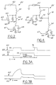
- An electrical drive circuit 20, as shown in FIG. 2 controls the operation of the injector 12 and has an inductor 22 which stores energy and discharges that energy to the injector 12 to more rapidly open the injector 12.
- the fuel system has a fuel tank 24 within which is received a fuel pump 26 which has an inlet 28 adjacent the bottom of the fuel tank 24 through which fuel is drawn into the fuel pump 26 and an outlet 30 communicating with an outlet 32 of the fuel tank 24 through which fuel is delivered under pressure to a fuel rail 33 in communication with the fuel injector 12.
- a vapor vent valve 34 is partially received in the upper fuel tank wall 36 and preferably has an outlet 38 in communication with a fuel vapor canister (not shown) which contains activated charcoal to absorb at least some of the fuel vapors delivered to the canister and reduce the emission of hydrocarbon vapors into the environment.
- the engine 10 has a piston 40 slidably received for reciprocation within the piston cylinder bore 18 and operably connected to a connecting rod 42 which is eccentrically connected to a crankshaft 44.
- An engine air intake throttle valve 46 communicates with a crankcase chamber 48 of the engine 10 to draw air into the crankcase chamber 48 which is communicated with the combustion chamber 16 through a transfer passage (not shown) and a port 49. Air drawn in through the intake throttle valve 46 provides oxygen to the combustion chamber 16 which is mixed with the fuel injected through the fuel injector 12 to facilitate combustion of the fuel when ignited by a spark plug 50.
- the reciprocating piston 40 opens and closes an exhaust passage 52 through which the products of the fuel combustion are exhausted.
- An engine control unit such as a microprocessor 54 monitors sensors of various engine operational parameters such as temperature sensors 55, 56, engine crankshaft position sensor 57, intake air flow rate or throttle opening position sensor 59, and manifold air pressure sensor 61 among others, to control the injection of fuel into the engine 10.
- the microprocessor 54 communicates with a conventional ignition coil 58 to control the timing of the spark plug 50. Further, the microprocessor 54 can be used to control the actuation of the drive circuit 20 which controls the operation of the injector 12.
- a directly injected two-stroke engine 10 In a directly injected two-stroke engine 10, an extremely short time is available to inject sufficient fuel into the combustion chamber 16 of the engine 10 especially at high engine speeds which, for a two-stroke engine can be about 12,000 revolutions per minute (RPM's) or more. At high engine speeds, the time available to inject fuel into such an engine can be about 3 milliseconds or less. Further, in a two-stroke engine, the injection occurs once per revolution of the crankshaft 44 as opposed to once every other revolution of the crankshaft 44 in a four-stroke engine. With this reduced time available for the fuel injection event, it is imperative that the fuel injector 12 be rapidly opened so that sufficient fuel may be delivered to the engine 10 to meet its increased fuel demands at high engine speeds and loads.
- RPM's revolutions per minute
- an electrical injector drive circuit 20 has an inductor 22 connected in series with the solenoid coil 62 of the fuel injector 12.
- the power source for the circuit is preferably an alternator supply driven by the engine 10 or a battery 63 of about 12 volts such as those common in automotive vehicles.
- An inductor driver switch 60 having a control input 65 is connected in series with the inductor 22 across the power source 63, and preferably has a protection diode 64 connected across it to limit the voltage across the switch 60.
- the inductor driver switch 60 is preferably a transistor such as a MOSFET switch which is common and commercially available.
- An injector driver switch 66 having a control input 67 which is also preferably a transistor MOSFET switch, is connected in series with the solenoid coil 62 to control the flow of current through the solenoid coil 62 and the opening and closing of the fuel injector valve.
- inductor 22, injector coil 62 and injector control switch 66 are connected in series across power source 63.
- Inductor driver switch 60 is in parallel to the series combination of the solenoid coil 62 and the injector driver switch 66.
- a protection diode 69 is also connected across this switch 66.
- the inductor driver switch 60 When the inductor driver switch 60 is turned on or closed by a control signal at its input 65, current is drawn through the inductor 22 and through the inductor driver switch 60. The current flow through the inductor 22 energizes the inductor 22 and stores electromagnetic energy therein.
- the inductor driver switch 60 When the inductor driver switch 60 is turned off and the injector driver switch 66 is turned on by a control signal at its input 67, current flows through the solenoid coil 62 of the fuel injector 12 to open it.
- the collapsing field at the inductor 22 causes the energy stored within the inductor to discharge into the solenoid coil 62, providing an increased current in the coil 62 to more rapidly open the fuel injector valve.
- a first control signal at each switch 60, 66 can turn the switches 60, 66 on and a second control signal can turn them off or, preferably, each switch 60, 66 is off in the absence of a control signal at its input 65, 67 and when a control signal is received at an input 65, 67 the associated switch 60, 66 is turned on.
- control signals received at the inputs 65, 67 of each switch 60, 66 may be derived from a single control signal from the microprocessor 54 to control the operation of the circuit 20 and each switch 60, 66 can be independently controlled by sending separate control signals to each input 65, 67.
- the inductor driver switch 60 is turned on before the injection event begins to precharge or store energy in the inductor 22.
- the injector driver switch 66 is preferably turned on slightly before the inductor driver switch 60 is turned off and generally only a few hundred microseconds before the inductor driver switch 60 is turned off. This insures that the injector driver switch 66 is completely on before the energy stored in the inductor 22 is discharged therefrom so that the energy stored in the inductor 22 will flow immediately to the fuel injector coil 62 when the inductor driver switch 60 is turned off. A very small amount of current may flow through the injector coil 62 when the injector driver switch 66 is initially turned on but this does not affect the operation of the injector 12.
- the injector driver switch 66 When the injector driver switch 66 is turned off, the fall time of the current is controlled by the characteristics of the two coils (inductor 22 and solenoid coil 62) in series. To reduce the time to close the injector 12, the influence of the inductor 22 can be removed by turning the inductor driver switch 60 on until the injector 12 has closed, as indicated at 76 in FIG. 3. Once the injector 12 has closed, the inductor driver switch 60 can be turned off again until the next cycle. Any current in the injector 12 developed at the end of the close time will be minimal and will not affect the proper operation of the injector 12.
- the time needed to open the injector 12 was decreased to 0.38 milliseconds as compared to an opening time of 1.4 milliseconds for a similar fuel injector 12 without the drive circuit 20. This dramatic reduction in opening time of the injector 12 permits increased fuel flow through the injector 12 during the relatively short time available for fuel injection.
- the inductance of the inductor 22 should be as large as possible while minimizing its resistance and size.
- An inductor 22 with an inductance that is similar to that of the solenoid coil 62 and a resistance that is about between 1/10th to 1/20th of that of the solenoid coil 62 has been experimentally determined to provide the desired results.
- a first current steering diode 72 is connected in series between inductor 22 and injector coil 62, and a second current steering diode 70 is connected across the series combination of inductor 22 and diode 72.
- the overall function of this drive circuit 20' is essentially the same as that in the first embodiment 20 previously described in that when the inductor driver switch 60 is turned on current flows through the inductor 22 and through the switch 60 to an electrical ground 68 to energize the inductor 22 and store energy therein.
- the injector driver switch 66 if the injector driver switch 66 is on simultaneously with the inductor driver switch 60, current may also flow to the solenoid coil 62 through diode 70 to open the injector 12 and inject fuel into the engine 10.
- the inductor 22 cannot be energized or precharged to store energy therein while the fuel injector 12 is open.
- the inductor 22 may be simultaneously precharged while the injector 12 is open thereby increasing the rate of repetition of the cycle of storing energy and discharging that energy into the injector coil 62 to more rapidly open the injector 12. This is important especially at high engine speeds wherein the engine 10 has an increased fuel demand which requires the injector 12 to remain open for a longer period of time and thereby reduces the time available to charge the inductor 22.
- the repeat rate of the energy storage and discharge cycle is improved from 11 milliseconds in the first embodiment (drive circuit 20) to 7.5 milliseconds in the second embodiment (drive circuit 20').
- the repeat rate of the first embodiment drive circuit 20 is suitable for an engine operating up to about 5,500 RPM's and the repeat rate of the second embodiment drive circuit 20' is suitable to control the fuel injection of an engine operating up to about 8,000 RPM's.
- the repeat rate of the fuel injector drive circuits 20, 20' can be further improved by increasing the flow rate of the injector 12 which will provide a reduced time to inject a given quantity of fuel or by using a lower resistance inductor 22 which would require a shorter precharge time.
- the electronic fuel injector drive circuits 20, 20' utilize low cost, common and commercially available electrical components arranged in relatively simple circuitry to provide an increased current to the fuel injector 12 to more rapidly open it. This provides increased control over the fuel injection event and is especially desirable for use with directly injected two-stroke engines which have a significantly reduced available time for fuel injection.
- the drive circuits 20, 20' are considerably less expensive and more effective than peak and hold or saturation type injector drivers.
- currently available microprocessors 54 which monitor various engine operational perimeters can be readily adapted to control the inductor driver switch 60 and the injector driver switch 66 in use to more efficiently operate the drive circuits 20, 20', fuel system and engine 10.
- an energy storage device (inductor 22) is first caused to store energy, and then connected in series with the vehicle power source to discharge into the injector coil.
Landscapes
- Engineering & Computer Science (AREA)
- Chemical & Material Sciences (AREA)
- Combustion & Propulsion (AREA)
- Mechanical Engineering (AREA)
- General Engineering & Computer Science (AREA)
- Fuel-Injection Apparatus (AREA)
- Electrical Control Of Air Or Fuel Supplied To Internal-Combustion Engine (AREA)
Applications Claiming Priority (2)
| Application Number | Priority Date | Filing Date | Title |
|---|---|---|---|
| US909964 | 1986-09-22 | ||
| US08/909,964 US5979412A (en) | 1997-08-12 | 1997-08-12 | Inductive discharge injector driver |
Publications (1)
| Publication Number | Publication Date |
|---|---|
| EP0897056A1 true EP0897056A1 (de) | 1999-02-17 |
Family
ID=25428116
Family Applications (1)
| Application Number | Title | Priority Date | Filing Date |
|---|---|---|---|
| EP98113504A Withdrawn EP0897056A1 (de) | 1997-08-12 | 1998-07-20 | Induktionsentladungstreiberschaltung für eine Einspritzdüse |
Country Status (3)
| Country | Link |
|---|---|
| US (1) | US5979412A (de) |
| EP (1) | EP0897056A1 (de) |
| JP (1) | JPH11107835A (de) |
Cited By (1)
| Publication number | Priority date | Publication date | Assignee | Title |
|---|---|---|---|---|
| WO1999042716A1 (en) * | 1998-02-20 | 1999-08-26 | Sturman Industries, Inc. | Pulsed-energy controllers and methods of operation thereof |
Families Citing this family (23)
| Publication number | Priority date | Publication date | Assignee | Title |
|---|---|---|---|---|
| US6363314B1 (en) | 2000-07-13 | 2002-03-26 | Caterpillar Inc. | Method and apparatus for trimming a fuel injector |
| US6415762B1 (en) | 2000-07-13 | 2002-07-09 | Caterpillar Inc. | Accurate deliver of total fuel when two injection events are closely coupled |
| US6606974B1 (en) | 2000-07-13 | 2003-08-19 | Caterpillar Inc | Partitioning of a governor fuel output into three separate fuel quantities in a stable manner |
| US6480781B1 (en) | 2000-07-13 | 2002-11-12 | Caterpillar Inc. | Method and apparatus for trimming an internal combustion engine |
| US6467452B1 (en) | 2000-07-13 | 2002-10-22 | Caterpillar Inc | Method and apparatus for delivering multiple fuel injections to the cylinder of an internal combustion engine |
| US6371077B1 (en) | 2000-07-13 | 2002-04-16 | Caterpillar Inc. | Waveform transitioning method and apparatus for multi-shot fuel systems |
| US6386176B1 (en) | 2000-07-13 | 2002-05-14 | Caterpillar Inc. | Method and apparatus for determining a start angle for a fuel injection associated with a fuel injection signal |
| US6390082B1 (en) | 2000-07-13 | 2002-05-21 | Caterpillar Inc. | Method and apparatus for controlling the current level of a fuel injector signal during sudden acceleration |
| US6705277B1 (en) | 2000-07-13 | 2004-03-16 | Caterpillar Inc | Method and apparatus for delivering multiple fuel injections to the cylinder of an engine wherein the pilot fuel injection occurs during the intake stroke |
| US6450149B1 (en) | 2000-07-13 | 2002-09-17 | Caterpillar Inc. | Method and apparatus for controlling overlap of two fuel shots in multi-shot fuel injection events |
| US6453874B1 (en) | 2000-07-13 | 2002-09-24 | Caterpillar Inc. | Apparatus and method for controlling fuel injection signals during engine acceleration and deceleration |
| US6363315B1 (en) | 2000-07-13 | 2002-03-26 | Caterpillar Inc. | Apparatus and method for protecting engine electronic circuitry from thermal damage |
| US6888268B1 (en) * | 2001-01-11 | 2005-05-03 | The Titan Corporation | Energy storage device |
| JP4596353B2 (ja) * | 2001-02-27 | 2010-12-08 | 株式会社デンソー | 電磁弁駆動装置 |
| US6516773B2 (en) | 2001-05-03 | 2003-02-11 | Caterpillar Inc | Method and apparatus for adjusting the injection current duration of each fuel shot in a multiple fuel injection event to compensate for inherent injector delay |
| US6516783B2 (en) | 2001-05-15 | 2003-02-11 | Caterpillar Inc | Camshaft apparatus and method for compensating for inherent injector delay in a multiple fuel injection event |
| US6953108B2 (en) * | 2003-04-04 | 2005-10-11 | Millenworks | Magnetorheological damper system |
| EP1671027A4 (de) * | 2003-09-10 | 2014-12-10 | Pcrc Products | Vorrichtung und verfahren zur steuerung des betriebs eines verbrennungsmotors mit einem elektronischen kraftstoffregelsystem |
| CN100510379C (zh) * | 2003-09-10 | 2009-07-08 | Pcrc产品有限公司 | 用于小型发动机的电子燃油调节系统 |
| JP2005223168A (ja) * | 2004-02-06 | 2005-08-18 | Mitsubishi Electric Corp | 電磁アクチュエータ及びその制御方法 |
| US9371786B2 (en) | 2011-08-24 | 2016-06-21 | Walbro Llc | Fuel injected engine system |
| US9097225B2 (en) * | 2013-01-10 | 2015-08-04 | Continental Automotive Systems, Inc. | Method to detect partial failure of direct-injection boost voltage |
| JP5849975B2 (ja) * | 2013-02-25 | 2016-02-03 | 株式会社デンソー | 燃料噴射制御装置および燃料噴射システム |
Citations (2)
| Publication number | Priority date | Publication date | Assignee | Title |
|---|---|---|---|---|
| EP0366622A2 (de) * | 1988-10-27 | 1990-05-02 | MARELLI AUTRONICA S.p.A. | Schaltung zum Ansteuern von induktiven Lasten, insbesondere zum Antreiben von Elektro-Einspritzventilen eines Dieselmotors |
| EP0995023A1 (de) * | 1997-07-09 | 2000-04-26 | Magneti Marelli France | Leistungssteuerschaltung für einen elektromagnetischen betätiger, wie einspritzventil oder elektromagnetventil |
Family Cites Families (7)
| Publication number | Priority date | Publication date | Assignee | Title |
|---|---|---|---|---|
| US3643129A (en) * | 1970-11-30 | 1972-02-15 | Gen Motors Corp | Solenoid control apparatus |
| US4327693A (en) * | 1980-02-01 | 1982-05-04 | The Bendix Corporation | Solenoid driver using single boost circuit |
| US4355619A (en) * | 1980-10-01 | 1982-10-26 | The Bendix Corporation | Fast response two coil solenoid driver |
| US4604675A (en) * | 1985-07-16 | 1986-08-05 | Caterpillar Tractor Co. | Fuel injection solenoid driver circuit |
| US4905120A (en) * | 1988-10-20 | 1990-02-27 | Caterpillar Inc. | Driver circuit for solenoid operated fuel injectors |
| IT1251259B (it) * | 1991-12-23 | 1995-05-05 | Elasis Sistema Ricerca Fiat | Circuito di comando di carichi prevalentemente induttivi, in particolare elettroiniettori. |
| ES2172569T3 (es) * | 1995-11-07 | 2002-10-01 | St Microelectronics Srl | Circuito de comando para un inyector. |
-
1997
- 1997-08-12 US US08/909,964 patent/US5979412A/en not_active Expired - Fee Related
-
1998
- 1998-07-20 EP EP98113504A patent/EP0897056A1/de not_active Withdrawn
- 1998-07-29 JP JP10213864A patent/JPH11107835A/ja not_active Withdrawn
Patent Citations (2)
| Publication number | Priority date | Publication date | Assignee | Title |
|---|---|---|---|---|
| EP0366622A2 (de) * | 1988-10-27 | 1990-05-02 | MARELLI AUTRONICA S.p.A. | Schaltung zum Ansteuern von induktiven Lasten, insbesondere zum Antreiben von Elektro-Einspritzventilen eines Dieselmotors |
| EP0995023A1 (de) * | 1997-07-09 | 2000-04-26 | Magneti Marelli France | Leistungssteuerschaltung für einen elektromagnetischen betätiger, wie einspritzventil oder elektromagnetventil |
Cited By (2)
| Publication number | Priority date | Publication date | Assignee | Title |
|---|---|---|---|---|
| WO1999042716A1 (en) * | 1998-02-20 | 1999-08-26 | Sturman Industries, Inc. | Pulsed-energy controllers and methods of operation thereof |
| US6005763A (en) * | 1998-02-20 | 1999-12-21 | Sturman Industries, Inc. | Pulsed-energy controllers and methods of operation thereof |
Also Published As
| Publication number | Publication date |
|---|---|
| US5979412A (en) | 1999-11-09 |
| JPH11107835A (ja) | 1999-04-20 |
Similar Documents
| Publication | Publication Date | Title |
|---|---|---|
| US5979412A (en) | Inductive discharge injector driver | |
| US6684862B2 (en) | Controller for internal combustion engine having fuel injection system | |
| KR950003760B1 (ko) | 가스 분사식 연료분사 시스템 | |
| US5430601A (en) | Electronic fuel injector driver circuit | |
| US4886032A (en) | Fuel injector heating method | |
| US7100578B2 (en) | Method for driving fuel injection pump | |
| US6293255B1 (en) | Fuel injection system | |
| EP0643219A1 (de) | Brennstoffversorgungssystem für eine Brennkraftmaschine | |
| US6109245A (en) | Apparatus and method for driving a piezoelectrically controlled fuel injection valve | |
| EP0849455A3 (de) | Vorrichtung und Verfahren zum Einspritzen von Brennstoff bei Brennkraftmaschinen mit Direkteinspritzung | |
| US6712048B2 (en) | Driving circuitry for electromagnetic fuel injection valve | |
| US5806504A (en) | Hybrid ignition circuit for an internal combustion engine | |
| US4870932A (en) | Fuel injection heating system | |
| EP1671027A2 (de) | Vorrichtung und verfahren zur steuerung des betriebs eines verbrennungsmotors mit einem elektronischen kraftstoffregelsystem | |
| WO2005026519A2 (en) | Electronic fuel regulation system for small engines | |
| US5183019A (en) | Idling control device for high pressure fuel injection engine | |
| US5239970A (en) | Fuel injection type engine | |
| US5090381A (en) | Method of and apparatus for controlling an idling control valve of an internal combustion engine | |
| GB2278248A (en) | Fuel injector driver with OFF current prevention | |
| EP0420288A2 (de) | Kraftstoffeinspritzsteuereinrichtung von Zweitaktmotor | |
| US5724938A (en) | Ignition system for a two cycle engine | |
| JP3268244B2 (ja) | 電磁弁駆動回路 | |
| JP3268245B2 (ja) | 電磁弁駆動回路 | |
| US7316217B2 (en) | Control device of internal combustion engine | |
| JP3424239B2 (ja) | 燃料噴射装置及び燃料噴射弁駆動回路 |
Legal Events
| Date | Code | Title | Description |
|---|---|---|---|
| PUAI | Public reference made under article 153(3) epc to a published international application that has entered the european phase |
Free format text: ORIGINAL CODE: 0009012 |
|
| AK | Designated contracting states |
Kind code of ref document: A1 Designated state(s): DE FR IT SE |
|
| AX | Request for extension of the european patent |
Free format text: AL;LT;LV;MK;RO;SI |
|
| 17P | Request for examination filed |
Effective date: 19990430 |
|
| AKX | Designation fees paid |
Free format text: DE FR IT SE |
|
| 17Q | First examination report despatched |
Effective date: 20010831 |
|
| GRAH | Despatch of communication of intention to grant a patent |
Free format text: ORIGINAL CODE: EPIDOS IGRA |
|
| STAA | Information on the status of an ep patent application or granted ep patent |
Free format text: STATUS: THE APPLICATION IS DEEMED TO BE WITHDRAWN |
|
| 18D | Application deemed to be withdrawn |
Effective date: 20030703 |