EP0896227A2 - Harness control system for civil electric plants, in particular for intercom or video intercom systems - Google Patents
Harness control system for civil electric plants, in particular for intercom or video intercom systems Download PDFInfo
- Publication number
- EP0896227A2 EP0896227A2 EP98202374A EP98202374A EP0896227A2 EP 0896227 A2 EP0896227 A2 EP 0896227A2 EP 98202374 A EP98202374 A EP 98202374A EP 98202374 A EP98202374 A EP 98202374A EP 0896227 A2 EP0896227 A2 EP 0896227A2
- Authority
- EP
- European Patent Office
- Prior art keywords
- intercom
- electric
- wires
- harness
- transmitter
- Prior art date
- Legal status (The legal status is an assumption and is not a legal conclusion. Google has not performed a legal analysis and makes no representation as to the accuracy of the status listed.)
- Granted
Links
Images


Classifications
-
- G—PHYSICS
- G01—MEASURING; TESTING
- G01R—MEASURING ELECTRIC VARIABLES; MEASURING MAGNETIC VARIABLES
- G01R31/00—Arrangements for testing electric properties; Arrangements for locating electric faults; Arrangements for electrical testing characterised by what is being tested not provided for elsewhere
- G01R31/50—Testing of electric apparatus, lines, cables or components for short-circuits, continuity, leakage current or incorrect line connections
- G01R31/58—Testing of lines, cables or conductors
Definitions
- the present invention refers to a harness control system for civil electric plants, in particular for intercom or video intercom systems, for access, safety and, in general, signal controls.
- said control has to be performed as many times as the number of internal units placed in the system and therefore, sometimes, especially in case of large residential buildings, it would be better to reduce said number of controls.
- control of the traditional type has to be conducted by at least two technicians, who exchange information on the quality of the reception of the transmitted message, generally by voice, if the distance between the external location and the internal unit allows such exchange by voice, or, otherwise, through a cellular phone, with consequent losses of time, telephone expenses, cost of personnel, possibility of mistakes and misunderstandings during the communication.
- a purpose of the present invention is to solve the above mentioned problems and in particular to indicate a harness control system for civil electric plants, in particular for intercom and/or video intercom systems, said system assuring a high flexibility of the electrical and/or electronic functions, and, at the same time, allowing to control the connections of the entire system in its open circuit conditions, i.e. before the final laying.
- Another purpose of the present invention is to provide a harness control system for intercom or video intercom systems such to control the connections between external locations and internal units even for short lengths of wiring, in order to locate possible installation faults or errors.
- Another purpose of the present invention is to provide a harness control system for video intercom systems of the digital type.
- a further purpose of the present invention is to provide a harness control system for intercom and for video intercom systems, so as to indicate installation defects to the user (cut wires, short circuited wires, inverted wires, wrong call) both in the case of call signal wires and of different types of wires.
- a further purpose of the present invention is to provide a harness control system for intercom and for video intercom systems, whereby a system can be provided without using complex electric or electronic technologies and/or expensive materials.
- the system according to the invention comprises at least an electric signal transmitter, connected to a power supply, which, during the control phase of the working conditions of the electric plant, is installed in place of the external push-button panel, so as to send electric signals through the wires.
- the system comprises a plurality of electric signal receiving means, wherein the receiving frequency is tuned with the transmitted signal frequency, said receiving means being installed in place of the intercom internal units and are used to formulate the diagnosis.
- the present invention is based on the principle that, if neither faults nor malfunctions are present on the connection lines, a signal transmitted as an input into the system has to be found as an identical output signal.
- a plurality of electronic reception stages and a decoder, provided with internal decoding logic, are provided to indicate the level of the signals received at the internal units and to direct said levels to the seven segments of a display with one alphanumeric figure, so that their starting sequence is driven by the sequence of said levels.
- T indicates the electric signal transmitter
- M indicates a pull-out terminal board of the transmitter T
- M2 indicates the terminals of said terminal board M
- M1 indicates a fixed terminal board of the transmitter T having pressure terminals M3.
- S and S1 indicate silk-screened plates, which indicate the exact relation between electric wires and terminals and which are useful for the proper insertion of the system cables into the terminals M2, M3.
- R indicates a receiver of electric signals, comprising a pull-out terminal board M4, a fixed terminal board M5, a first area D of a display screen, wherein a series of LED diodes turn on in sequence, a second area D2 of the display screen to visualise alpha-numeric characters and silk-screened plates D1, S2, S3 to properly connect the electric cables of the plant to the terminals of the terminal board M4, M5; in fact, thanks to these bijection tables, it is possible to control the working conditions of any type of intercom and/or video-intercom system.
- MD and MD1 indicate, for instance, two call modules (one module with two push-buttons and a loudspeaker and the other module with four push-buttons), which can be present in a modular push-button panel P of an external location for calling the floors; 10 indicates an electric double-wire-cable which connects the push-button panel P to an electric lock SE of the building main-gate, 13 indicates a four-wire-electric cable which connects the push-button panel P to a power supply A, whilst SD indicates a shunt module which connects a plurality of internal units; 11 and 12 indicate, respectively, an "n" wire (wherein n is the number of internal units connected to the push-button panel P) and a four-wire-electric cable, which connect the push-button panel P to the shunt module SD, whilst 14 and 15 indicate two cables (having 4+n wires inside) coming out from the SD module.
- 16 indicates a five-wire-electric cable, which connects the SD module to a possible second internal unit
- 17 indicates a five-wire-electric cable, which connects the SD module to a first internal location on the plane and, then, to the internal units CP, CS
- SS indicates a possible additional signal bell
- whilst 18 indicates a five-wire-shunt cable for connecting a possible second internal unit CP, CS parallel to the first.
- the only differences consist in adding a camera module, indicated by TL and positioned on the push-button panel P, in the type of the internal units (the ones with the display screen are indicated with VCS), in the shunt module SDV, provided with a terminal board MSV and in the number of electric wires which are inside the cables.
- 20 indicates a seven-wire-electric cable, which connects the push-button panel P to the power supply A
- 21 indicates a seven-wire-electric cable which connects the push-button panel P to the module SDV
- 23 and 24 indicate two cables with seven and n wires, respectively, wherein n is the number of internal units connected to the push-button panel P, and said cables come out from the module SDV
- 25 indicates an eight-wire-electric cable, which connects the module SDV to a first inside location provided with internal units VCS
- 26 and 27 indicate an eight and a five-wire-electric cables, which connect, in parallel, an output of the shunt device on the plane to a video intercom internal unit VCS and to an intercom internal unit CP.
- the transmitter apparatus T comprises an accumulator battery BT, connected to a power supply circuit CA and to a waveform generator GF; the transmission device further comprises a series of input buffers (equal, in number, to the number of wires to be controlled) and a terminal board MR for sending the electric signals.
- the number of the system wires CV, which can be controlled simultaneously is equal to 10, plus the call wires.
- the receiver R comprises a final terminal board MR1, a receiver device, comprising a series of buffers BF1 (equal, in number, to the number of wires to be controlled), a series of indicators LD of the level of the incoming electric signal, a decoder device DC, which sends the electric signal level to the segments of the zone D2 of the screen DA, wherein alphanumeric characters are visualised.
- a receiver device comprising a series of buffers BF1 (equal, in number, to the number of wires to be controlled), a series of indicators LD of the level of the incoming electric signal, a decoder device DC, which sends the electric signal level to the segments of the zone D2 of the screen DA, wherein alphanumeric characters are visualised.
- the transmitter T Before connecting the electric cables to the ends of the plant and, therefore, through an open circuit operation, the transmitter T is positioned in place of the push-button panel P of the external location, i.e. at the beginning of each harness section wherein the control is desired.
- the receiver R can be positioned in place of each internal unit CS, CP, VCS (direct connection) or at the end of each section to be controlled (indirect connections).
- the transmitter T can be moved along the harness, so as to control the connections on the shorter sections; in fact, the harness sections to be controlled can have, at will, very short distances, in order to locate the problem more easily, through a put and take process.
- a waveform generated by the generator GF is sent to each one of the electric cables to be controlled, but, alternatively, a different waveform could be sent to some or to all the connection wires.
- the signal type can be changed (from square wave to triangular wave, to sawtoothed wave, to ramp waveform and so on), as long as the duration of the generated pulse is sufficient to keep lighted a display device, as for instance a LED diode, for a period of time at least equal to the persistence of vision in the human eye retina, so as to allow a user to notice the various lighting.
- the duration of the pulse is equal to at least one second and the amplitude of the square wave is equal to 3-9 Volt (including the extreme values).
- the connections of the transmitter T are executed by placing the electric cables of the plant on the terminal boards M, M1 in the order established by the plates S, S1 and, therefore, the waveforms are sent to each wire.
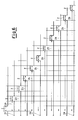
- a microcontrol placed inside the decoder DC executes a reading of the signals on every input IN of the wires to be controlled, following the sequence illustrated in Figure 6, wherein Z is the duration of the square wave (equal, for instance to one second) and Z1, Z2, Z3, Z4, Z5, Z6, Z7, Z8, Z9, Z0 are the time periods whereby the square wave is delayed at the various inputs IN (in this case, Z0 is equal to about 20 seconds).
- Said sequence is necessary to sequentially light the LED diodes of the display screen DA; in fact, the decoder electronic circuit DC senses the levels of the input signals and sends said levels to the screen DA, so as to drive or do not drive the lighting of the LED diode (or LED diodes) corresponding to the electric cable (or cables) where an anomaly has been found.
- all the LED diodes of the screen DA should light in sequence (i.e., starting from the second LED, at two, four, six, eight, ten, twelve, fourteen, sixteen, eighteen and twenty seconds after the first LED lights, respectively).
- the call push-buttons can be grouped in modules of four push-buttons, therefore, in such case, it is convenient to provide an area D2 of the screen DA wherein a seven segments alphanumeric character is displayed, corresponding to the group of four call push-buttons under examination.
- connection between the transmitter T and the receiver R refers to a specific group of call wires
- the corresponding letter (a, b, c, d) shall appear in the area D2; otherwise, if the visualised letter does not match the push button group from which the call is originated, that is sign of a connection error.
- the circuit scheme of an intercom system comprises a shunt device SD, which allows the connection of a plurality of internal places, to start from the plane shunt; said apparatus is simple to provide and works in a substantially known manner.
- the shunt device SDV of a video intercom system ( Figure 4) is much more complex, since the number of electric cables to be connected together is much higher; then, in order to control the harness of the video intercom systems, the shunt device SDV can be substituted by a specific device, which has to be connected with the transmitter T and the receiver R.
- the transmitter T and the receiver R are provided with fixed and/or removable terminal boards, so as to adapt to different types of electric systems and that the diagnosis can be done also with systems of the digital type, section by section, by means of wired terminal boards.
Landscapes
- Physics & Mathematics (AREA)
- General Physics & Mathematics (AREA)
- Interconnected Communication Systems, Intercoms, And Interphones (AREA)
- Selective Calling Equipment (AREA)
- Closed-Circuit Television Systems (AREA)
Abstract
Description
- The present invention refers to a harness control system for civil electric plants, in particular for intercom or video intercom systems, for access, safety and, in general, signal controls.
- Currently, the control of the working conditions of an intercom or of a video intercom system of a civil building is done, after the harness of the entire system has been laid down, through a direct control of the quality of the communication between a technician, who sends test messages from the external location, and at least another operator, who receives the messages coming out from the inside terminals placed in the various floors of the building.
- Then, said control has to be performed as many times as the number of internal units placed in the system and therefore, sometimes, especially in case of large residential buildings, it would be better to reduce said number of controls.
- Further, the way said controls are done has some disadvantages; first of all, the control is done when the harness has been completed and therefore a malfunction would require the operators to disassemble what had been previously set up; secondly, finding a malfunction or an interruption in the communication between the external location and an internal unit does not give any information in order to locate the fault, and thus the technicians have to thoroughly control the whole connection line.
- Finally, said control of the traditional type has to be conducted by at least two technicians, who exchange information on the quality of the reception of the transmitted message, generally by voice, if the distance between the external location and the internal unit allows such exchange by voice, or, otherwise, through a cellular phone, with consequent losses of time, telephone expenses, cost of personnel, possibility of mistakes and misunderstandings during the communication.
- A purpose of the present invention is to solve the above mentioned problems and in particular to indicate a harness control system for civil electric plants, in particular for intercom and/or video intercom systems, said system assuring a high flexibility of the electrical and/or electronic functions, and, at the same time, allowing to control the connections of the entire system in its open circuit conditions, i.e. before the final laying.
- Another purpose of the present invention is to provide a harness control system for intercom or video intercom systems such to control the connections between external locations and internal units even for short lengths of wiring, in order to locate possible installation faults or errors.
- Another purpose of the present invention is to provide a harness control system for video intercom systems of the digital type.
- A further purpose of the present invention is to provide a harness control system for intercom and for video intercom systems, so as to indicate installation defects to the user (cut wires, short circuited wires, inverted wires, wrong call) both in the case of call signal wires and of different types of wires.
- A further purpose of the present invention is to provide a harness control system for intercom and for video intercom systems, whereby a system can be provided without using complex electric or electronic technologies and/or expensive materials.
- Said purposes are achieved by a harness control system for civil electric plants, in particular for intercom and/or video intercom systems, as claimed in
claim 1, which is indicated for reference. - Advantageously, the system according to the invention comprises at least an electric signal transmitter, connected to a power supply, which, during the control phase of the working conditions of the electric plant, is installed in place of the external push-button panel, so as to send electric signals through the wires.
- Additionally, the system comprises a plurality of electric signal receiving means, wherein the receiving frequency is tuned with the transmitted signal frequency, said receiving means being installed in place of the intercom internal units and are used to formulate the diagnosis.
- The present invention is based on the principle that, if neither faults nor malfunctions are present on the connection lines, a signal transmitted as an input into the system has to be found as an identical output signal.
- A plurality of electronic reception stages and a decoder, provided with internal decoding logic, are provided to indicate the level of the signals received at the internal units and to direct said levels to the seven segments of a display with one alphanumeric figure, so that their starting sequence is driven by the sequence of said levels.
- Additional features and advantages of the invention will be more evident from the description of a preferred, non-limiting embodiment of a harness control system for intercom and/or video intercom systems, according to the present invention, said system being illustrated, as a non-limiting example, in the accompanying schematic drawings, in which:
- Figure 1 is a front view of an example of embodiment of a transmitter means used in the harness control system, according to the present invention;
- Figure 2 is a front view of an example of embodiment of a receiver means used in the harness control system, according to the present invention;
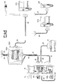
- Figure 3 is a schematic view of a possible embodiment of a harness installation of an intercom system;
- Figure 4 is a schematic view of a possible embodiment of a harness installation of a video intercom system;
- Figure 5 is a block diagram of the harness control system for electric plants, in particular for intercom and/or video intercom systems, according to the present invention;
- Figure 6 shows a diagram of the electric signal wave-forms in function of time, which are sent to all the system wires.
-
- With reference to the above figures, T indicates the electric signal transmitter, M indicates a pull-out terminal board of the transmitter T, M2 indicates the terminals of said terminal board M, whilst M1 indicates a fixed terminal board of the transmitter T having pressure terminals M3.
- Further, S and S1 indicate silk-screened plates, which indicate the exact relation between electric wires and terminals and which are useful for the proper insertion of the system cables into the terminals M2, M3.
- R indicates a receiver of electric signals, comprising a pull-out terminal board M4, a fixed terminal board M5, a first area D of a display screen, wherein a series of LED diodes turn on in sequence, a second area D2 of the display screen to visualise alpha-numeric characters and silk-screened plates D1, S2, S3 to properly connect the electric cables of the plant to the terminals of the terminal board M4, M5; in fact, thanks to these bijection tables, it is possible to control the working conditions of any type of intercom and/or video-intercom system.
- Referring in particular to Figures 3 and 4, MD and MD1 indicate, for instance, two call modules (one module with two push-buttons and a loudspeaker and the other module with four push-buttons), which can be present in a modular push-button panel P of an external location for calling the floors; 10 indicates an electric double-wire-cable which connects the push-button panel P to an electric lock SE of the building main-gate, 13 indicates a four-wire-electric cable which connects the push-button panel P to a power supply A, whilst SD indicates a shunt module which connects a plurality of internal units; 11 and 12 indicate, respectively, an "n" wire (wherein n is the number of internal units connected to the push-button panel P) and a four-wire-electric cable, which connect the push-button panel P to the shunt module SD, whilst 14 and 15 indicate two cables (having 4+n wires inside) coming out from the SD module.
- 16 indicates a five-wire-electric cable, which connects the SD module to a possible second internal unit; 17 indicates a five-wire-electric cable, which connects the SD module to a first internal location on the plane and, then, to the internal units CP, CS; SS indicates a possible additional signal bell; whilst 18 indicates a five-wire-shunt cable for connecting a possible second internal unit CP, CS parallel to the first.
- In the case of a video intercom installation, as shown in Figure 4, the cable connections are similar and the functional blocks indicated by the same reference, compared to Figure 3, have the same features.
- The only differences consist in adding a camera module, indicated by TL and positioned on the push-button panel P, in the type of the internal units (the ones with the display screen are indicated with VCS), in the shunt module SDV, provided with a terminal board MSV and in the number of electric wires which are inside the cables.
- 20 indicates a seven-wire-electric cable, which connects the push-button panel P to the power supply A, 21 indicates a seven-wire-electric cable which connects the push-button panel P to the module SDV; 23 and 24 indicate two cables with seven and n wires, respectively, wherein n is the number of internal units connected to the push-button panel P, and said cables come out from the module SDV; 25 indicates an eight-wire-electric cable, which connects the module SDV to a first inside location provided with internal units VCS; 26 and 27 indicate an eight and a five-wire-electric cables, which connect, in parallel, an output of the shunt device on the plane to a video intercom internal unit VCS and to an intercom internal unit CP.
- The transmitter apparatus T comprises an accumulator battery BT, connected to a power supply circuit CA and to a waveform generator GF; the transmission device further comprises a series of input buffers (equal, in number, to the number of wires to be controlled) and a terminal board MR for sending the electric signals.
- In a non-limiting, preferred embodiment of the present invention, the number of the system wires CV, which can be controlled simultaneously, is equal to 10, plus the call wires.
- In such case, if the number of the system wires is greater than ten, a corresponding number of equal control operations will be conducted, one after the other, on the remaining wires to be controlled.
- The receiver R comprises a final terminal board MR1, a receiver device, comprising a series of buffers BF1 (equal, in number, to the number of wires to be controlled), a series of indicators LD of the level of the incoming electric signal, a decoder device DC, which sends the electric signal level to the segments of the zone D2 of the screen DA, wherein alphanumeric characters are visualised.
- In order to control the proper connections of a civil electric plant, in particular an intercom or a video intercom, the following procedure is followed.
- Before connecting the electric cables to the ends of the plant and, therefore, through an open circuit operation, the transmitter T is positioned in place of the push-button panel P of the external location, i.e. at the beginning of each harness section wherein the control is desired.
- The receiver R can be positioned in place of each internal unit CS, CP, VCS (direct connection) or at the end of each section to be controlled (indirect connections).
- Also the transmitter T can be moved along the harness, so as to control the connections on the shorter sections; in fact, the harness sections to be controlled can have, at will, very short distances, in order to locate the problem more easily, through a put and take process.
- In this way, the electrical connections of the power supply A and of the plant wires, which carry the electric signal, including the call wires.
- This is obtained by sending inside the wires a waveform generated by the generator GF and by evaluating the parameters of the waveform received as an output; preferably, a square wave is sent to each one of the electric cables to be controlled, but, alternatively, a different waveform could be sent to some or to all the connection wires. Further, also the signal type can be changed (from square wave to triangular wave, to sawtoothed wave, to ramp waveform and so on), as long as the duration of the generated pulse is sufficient to keep lighted a display device, as for instance a LED diode, for a period of time at least equal to the persistence of vision in the human eye retina, so as to allow a user to notice the various lighting.
- In a non-limiting and exemplifying embodiment, the duration of the pulse is equal to at least one second and the amplitude of the square wave is equal to 3-9 Volt (including the extreme values).
- The connections of the transmitter T are executed by placing the electric cables of the plant on the terminal boards M, M1 in the order established by the plates S, S1 and, therefore, the waveforms are sent to each wire.
- Usually, ten wires are connected, plus the call wires, and the receiver is able to recognise the levels of the received signals; a microcontrol placed inside the decoder DC executes a reading of the signals on every input IN of the wires to be controlled, following the sequence illustrated in Figure 6, wherein Z is the duration of the square wave (equal, for instance to one second) and Z1, Z2, Z3, Z4, Z5, Z6, Z7, Z8, Z9, Z0 are the time periods whereby the square wave is delayed at the various inputs IN (in this case, Z0 is equal to about 20 seconds).
- Said sequence is necessary to sequentially light the LED diodes of the display screen DA; in fact, the decoder electronic circuit DC senses the levels of the input signals and sends said levels to the screen DA, so as to drive or do not drive the lighting of the LED diode (or LED diodes) corresponding to the electric cable (or cables) where an anomaly has been found.
- If the connections have been executed properly, all the LED diodes of the screen DA should light in sequence (i.e., starting from the second LED, at two, four, six, eight, ten, twelve, fourteen, sixteen, eighteen and twenty seconds after the first LED lights, respectively).
- If this does not happen, various cases can happen, said cases are herein examined: if the LED diode adjacent to the number of the electric cable indicated on the silk-screened plate D1 does not light, it means that the electric cable itself is interrupted; if two or more LED diodes light, it means that the corresponding electric cables are short circuited, while if the LED diodes do not light in the programmed sequence, it means that the corresponding electric cables are inverted.
- In the traditional intercom plants, the call push-buttons can be grouped in modules of four push-buttons, therefore, in such case, it is convenient to provide an area D2 of the screen DA wherein a seven segments alphanumeric character is displayed, corresponding to the group of four call push-buttons under examination.
- Obviously, if the connection between the transmitter T and the receiver R refers to a specific group of call wires, the corresponding letter (a, b, c, d) shall appear in the area D2; otherwise, if the visualised letter does not match the push button group from which the call is originated, that is sign of a connection error.
- However, it is important that the sequential orderly lighting of the LED diodes precedes the lighting of the letter segments corresponding to the group of the call push-button, so that the technician who installs the system can conduct the controls one at a time, without mixing the operations and the results and by paying attention first to the LED and, subsequently, to the alphanumeric display.
- As is clearly seen from Figures 3 and 4, the circuit scheme of an intercom system comprises a shunt device SD, which allows the connection of a plurality of internal places, to start from the plane shunt; said apparatus is simple to provide and works in a substantially known manner.
- On the contrary, the shunt device SDV of a video intercom system (Figure 4) is much more complex, since the number of electric cables to be connected together is much higher; then, in order to control the harness of the video intercom systems, the shunt device SDV can be substituted by a specific device, which has to be connected with the transmitter T and the receiver R.
- It has to be noticed once again the fact that the transmitter T and the receiver R are provided with fixed and/or removable terminal boards, so as to adapt to different types of electric systems and that the diagnosis can be done also with systems of the digital type, section by section, by means of wired terminal boards.
- Finally, it should be understood that, through such a solution, it is necessary to feed only the transmitter T and not also the receiver R.
- From the above description, the features and the advantages of the harness control system for civil electric plants, in particular for intercom and/or video intercom systems, according to the present invention are clear.
- The advantages are, in particular, the following:
- a simple control and diagnosis procedure for anomalies which can be present in the harness of an electric plant; further, said control and diagnosis procedure can be assigned to just one operator;
- possibility of intervening in a short time to solve the problem, without having to completely disassemble the plant;
- possibility of locating the anomaly in the wires, through a put and take technique;
- operation costs substantially reduced in comparison to the known art;
- flexibility of use and all-purpose use.
- It is clear that several changes can be done to the harness control system by the skilled in the art, in particular to the intercom and video intercom systems, which are the subject of the present invention, without leaving the scope of protection of the invention, it is also clear that, in the embodiments of the invention, the shapes of the illustrated details can be different and these same details can be substituted by technically equivalent elements.
Claims (11)
- Harness control system for civil electric plants, in particular for intercom and/or video intercom systems, of the analogue or digital type, characterised by comprising at least a transmitter device (T) and at least a receiver device (R) of electric signals, which are sent inside system wires (CV), in order to find and locate, at least along a wire section, working anomalies in said systems before their final installation.
- System as claimed in claim 1, characterised in that said transmitter device (T) is positioned at the beginning of said wire section and that said transmitter sends, in an open circuit configuration, at least a waveform inside at least a system wire (CV), said waveform being received by said receiver device (R), which is previously set on the frequency of the emitted signal and which is positioned at the end of said wire section.
- System as claimed in claim 1, characterised in that said transmitter device (T) comprises at least a power supply source (BT), at least a power supply circuit (CA), at least a waveform generator (GF) and at least an output stage (BF) to send the electric signals inside the system wires (CV).
- System as claimed in claim 2, characterised in that said transmitter device (T) replaces an external unit (P) of an intercom and/or video intercom system and in that a receiver device (R) replaces each internal unit (CS, CP, VCS) of said plant.
- System as claimed in claim 2, characterised in that said waveform is formed by a square wave which has a pulse duration of at least one second and an amplitude value comprised between 3 and 9 Volt, including the two extreme values.
- System as claimed in claim 3, characterised in that said input stage (BF) comprises at least five inputs (IN), in order to control the proper harness of the call wires and of wires other than call wires in the intercom and/or video intercom systems.
- System as claimed in claim 1, characterised in that said receiver device (R) comprises at least one input stage (BF1) of the electric signal sent by said transmitter device (T), at least a decoder means (DC) of the received signal level and a plurality of LED diodes (LD) to visualise any found anomaly on the screen (DA).
- System as claimed in claim 7, characterised in that each LED diode (LD) is univocally connected to an electric cable of said plant and in that, if said LED diode (LD) does not light, it means that said electric cable is interrupted, while, if two or more LED diodes (LD) light simultaneously, it means that the corresponding electric cables are short circuited, and, if the LED diodes (LD) corresponding to all the connected electric cables light with a sequence different from the predefined sequence, it means that at least two of said electric cables are inverted.
- System as claimed in claim 1, characterised in that said transmitter device (T) and/or said receiver device (R) comprise at least a fixed terminal board (M1, M5) and/or at least a removable terminal board (M, M4).
- System as claimed in claim 8, characterised in that said decoder means (DC) directs the input signal level to a display device (DA) provided with a seven segment alphanumeric character, relative to a predefined group of call push-buttons of an intercom and/or video intercom system.
- System as claimed in claim 10, characterised in that the display of said alphanumeric character on said device (DA) follows the lighting of said LED diodes (LD).
Priority Applications (1)
| Application Number | Priority Date | Filing Date | Title |
|---|---|---|---|
| SI9830383T SI0896227T1 (en) | 1997-08-05 | 1998-07-15 | Harness control system for civil electric installations, in particular for intercom or video intercom systems |
Applications Claiming Priority (2)
| Application Number | Priority Date | Filing Date | Title |
|---|---|---|---|
| ITMI971887 | 1997-08-05 | ||
| IT97MI001887A IT1294306B1 (en) | 1997-08-05 | 1997-08-05 | WIRING VERIFICATION SYSTEM FOR ELECTRICAL SYSTEMS FOR CIVIL USE, IN PARTICULAR FOR INTERCOM AND / OR VIDEO DOOR PHONE SYSTEMS |
Publications (3)
| Publication Number | Publication Date |
|---|---|
| EP0896227A2 true EP0896227A2 (en) | 1999-02-10 |
| EP0896227A3 EP0896227A3 (en) | 1999-07-28 |
| EP0896227B1 EP0896227B1 (en) | 2003-01-08 |
Family
ID=11377729
Family Applications (1)
| Application Number | Title | Priority Date | Filing Date |
|---|---|---|---|
| EP98202374A Expired - Lifetime EP0896227B1 (en) | 1997-08-05 | 1998-07-15 | Harness control system for civil electric installations, in particular for intercom or video intercom systems |
Country Status (6)
| Country | Link |
|---|---|
| EP (1) | EP0896227B1 (en) |
| AT (1) | ATE230852T1 (en) |
| DE (1) | DE69810545T2 (en) |
| ES (1) | ES2189081T3 (en) |
| IT (1) | IT1294306B1 (en) |
| SI (1) | SI0896227T1 (en) |
Citations (6)
| Publication number | Priority date | Publication date | Assignee | Title |
|---|---|---|---|---|
| US4418312A (en) * | 1981-10-23 | 1983-11-29 | Bell Telephone Laboratories, Incorporated | Apparatus for testing multi-conductor cables |
| US4445086A (en) * | 1982-02-22 | 1984-04-24 | The Boeing Company | Multiconductor cable tester |
| DE3701070A1 (en) * | 1986-01-21 | 1987-07-23 | Beha C Gmbh | Circuit arrangement for identifying electrical lines |
| JPS642458A (en) * | 1987-06-25 | 1989-01-06 | Matsushita Electric Works Ltd | Interphone equipment with monitor |
| US4937519A (en) * | 1988-08-16 | 1990-06-26 | Jupiter Toy Company | Apparatus and method for identifying conductors |
| JPH0792217A (en) * | 1993-09-27 | 1995-04-07 | Matsushita Electric Works Ltd | Wiring checker for apartment house |
-
1997
- 1997-08-05 IT IT97MI001887A patent/IT1294306B1/en active IP Right Grant
-
1998
- 1998-07-15 EP EP98202374A patent/EP0896227B1/en not_active Expired - Lifetime
- 1998-07-15 AT AT98202374T patent/ATE230852T1/en not_active IP Right Cessation
- 1998-07-15 ES ES98202374T patent/ES2189081T3/en not_active Expired - Lifetime
- 1998-07-15 DE DE69810545T patent/DE69810545T2/en not_active Expired - Fee Related
- 1998-07-15 SI SI9830383T patent/SI0896227T1/en unknown
Patent Citations (6)
| Publication number | Priority date | Publication date | Assignee | Title |
|---|---|---|---|---|
| US4418312A (en) * | 1981-10-23 | 1983-11-29 | Bell Telephone Laboratories, Incorporated | Apparatus for testing multi-conductor cables |
| US4445086A (en) * | 1982-02-22 | 1984-04-24 | The Boeing Company | Multiconductor cable tester |
| DE3701070A1 (en) * | 1986-01-21 | 1987-07-23 | Beha C Gmbh | Circuit arrangement for identifying electrical lines |
| JPS642458A (en) * | 1987-06-25 | 1989-01-06 | Matsushita Electric Works Ltd | Interphone equipment with monitor |
| US4937519A (en) * | 1988-08-16 | 1990-06-26 | Jupiter Toy Company | Apparatus and method for identifying conductors |
| JPH0792217A (en) * | 1993-09-27 | 1995-04-07 | Matsushita Electric Works Ltd | Wiring checker for apartment house |
Non-Patent Citations (2)
| Title |
|---|
| PATENT ABSTRACTS OF JAPAN vol. 013, no. 173 (E-748), 24 April 1989 -& JP 64 002458 A (MATSUSHITA ELECTRIC WORKS LTD), 6 January 1989 * |
| PATENT ABSTRACTS OF JAPAN vol. 095, no. 007, 31 August 1995 & JP 07 092217 A (MATSUSHITA ELECTRIC WORKS LTD), 7 April 1995 * |
Also Published As
| Publication number | Publication date |
|---|---|
| EP0896227B1 (en) | 2003-01-08 |
| SI0896227T1 (en) | 2003-06-30 |
| ATE230852T1 (en) | 2003-01-15 |
| DE69810545D1 (en) | 2003-02-13 |
| IT1294306B1 (en) | 1999-03-24 |
| DE69810545T2 (en) | 2003-11-20 |
| ES2189081T3 (en) | 2003-07-01 |
| EP0896227A3 (en) | 1999-07-28 |
| ITMI971887A1 (en) | 1999-02-05 |
Similar Documents
| Publication | Publication Date | Title |
|---|---|---|
| US3891811A (en) | Wire pair identification system | |
| US6201853B1 (en) | Telephone technician's remote assist apparatus and method | |
| CN100334456C (en) | Method and apparatus for distinguishing cable by simultaneous supplying of tone and intermittent link | |
| EP0896227B1 (en) | Harness control system for civil electric installations, in particular for intercom or video intercom systems | |
| CN110988580A (en) | Secondary cable alignment system and alignment method thereof | |
| US5764725A (en) | Apparatus for testing the line continuity of telephone switch equipment | |
| CN109493776A (en) | A kind of display panel test fixture and its test method | |
| WO1988003653A1 (en) | Wire tester | |
| US7209553B2 (en) | Cutover method and device for telephone lines | |
| KR920005012B1 (en) | Signalling service functions testing method | |
| GB2330421A (en) | A cable testing system | |
| JP2000347720A (en) | Testing device | |
| KR102117162B1 (en) | Self-diagnosis type line test box | |
| KR102321808B1 (en) | Line check system and method of page phone facility | |
| KR0148889B1 (en) | Method and apparatus for testing keyphone system | |
| KR920000066B1 (en) | Method & apparatus of monitoring circuit | |
| KR940008776B1 (en) | Communication system with optical fiber cable | |
| JPH0316059B2 (en) | ||
| JPS5895486A (en) | Portable telephone subscariber's line tester | |
| JP2003075495A (en) | Continuity inspection apparatus of elevator | |
| CN115639758A (en) | Control system for aging operation of branching acquisition equipment | |
| KR20000003651U (en) | Jumper Automatic Switching Device | |
| JPH03505953A (en) | Apparatus and method for mapping connection status of a communication system having multiple communication paths | |
| SU1061167A1 (en) | Device for remote indicating of presence of limited positions | |
| Table | Specifications |
Legal Events
| Date | Code | Title | Description |
|---|---|---|---|
| PUAI | Public reference made under article 153(3) epc to a published international application that has entered the european phase |
Free format text: ORIGINAL CODE: 0009012 |
|
| AK | Designated contracting states |
Kind code of ref document: A2 Designated state(s): AT BE CH DE ES FR GB GR IT LI NL PT |
|
| AX | Request for extension of the european patent |
Free format text: AL;LT;LV;MK;RO;SI |
|
| PUAL | Search report despatched |
Free format text: ORIGINAL CODE: 0009013 |
|
| AK | Designated contracting states |
Kind code of ref document: A3 Designated state(s): AT BE CH CY DE DK ES FI FR GB GR IE IT LI LU MC NL PT SE |
|
| AX | Request for extension of the european patent |
Free format text: AL;LT;LV;MK;RO;SI |
|
| 17P | Request for examination filed |
Effective date: 20000119 |
|
| AKX | Designation fees paid |
Free format text: AT BE CH CY DE DK ES FI FR GB GR LI |
|
| AXX | Extension fees paid |
Free format text: SI PAYMENT 19991125 |
|
| RBV | Designated contracting states (corrected) |
Designated state(s): AT BE CH DE ES FR GB GR IT LI NL PT |
|
| 17Q | First examination report despatched |
Effective date: 20010615 |
|
| GRAG | Despatch of communication of intention to grant |
Free format text: ORIGINAL CODE: EPIDOS AGRA |
|
| RTI1 | Title (correction) |
Free format text: HARNESS CONTROL SYSTEM FOR CIVIL ELECTRIC INSTALLATIONS, IN PARTICULAR FOR INTERCOM OR VIDEO INTERCOM SYSTEMS |
|
| GRAG | Despatch of communication of intention to grant |
Free format text: ORIGINAL CODE: EPIDOS AGRA |
|
| GRAH | Despatch of communication of intention to grant a patent |
Free format text: ORIGINAL CODE: EPIDOS IGRA |
|
| GRAH | Despatch of communication of intention to grant a patent |
Free format text: ORIGINAL CODE: EPIDOS IGRA |
|
| GRAA | (expected) grant |
Free format text: ORIGINAL CODE: 0009210 |
|
| AK | Designated contracting states |
Kind code of ref document: B1 Designated state(s): AT BE CH DE ES FR GB GR IT LI NL PT |
|
| AX | Request for extension of the european patent |
Free format text: SI PAYMENT 19991125 |
|
| REF | Corresponds to: |
Ref document number: 230852 Country of ref document: AT Date of ref document: 20030115 Kind code of ref document: T |
|
| REG | Reference to a national code |
Ref country code: GB Ref legal event code: FG4D |
|
| REG | Reference to a national code |
Ref country code: CH Ref legal event code: EP |
|
| REF | Corresponds to: |
Ref document number: 69810545 Country of ref document: DE Date of ref document: 20030213 Kind code of ref document: P |
|
| REG | Reference to a national code |
Ref country code: CH Ref legal event code: NV Representative=s name: AMMANN PATENTANWAELTE AG BERN |
|
| REG | Reference to a national code |
Ref country code: GR Ref legal event code: EP Ref document number: 20030401122 Country of ref document: GR |
|
| REG | Reference to a national code |
Ref country code: ES Ref legal event code: FG2A Ref document number: 2189081 Country of ref document: ES Kind code of ref document: T3 |
|
| ET | Fr: translation filed | ||
| PLBE | No opposition filed within time limit |
Free format text: ORIGINAL CODE: 0009261 |
|
| STAA | Information on the status of an ep patent application or granted ep patent |
Free format text: STATUS: NO OPPOSITION FILED WITHIN TIME LIMIT |
|
| 26N | No opposition filed |
Effective date: 20031009 |
|
| REG | Reference to a national code |
Ref country code: SI Ref legal event code: IF |
|
| PGFP | Annual fee paid to national office [announced via postgrant information from national office to epo] |
Ref country code: PT Payment date: 20080625 Year of fee payment: 11 |
|
| PGFP | Annual fee paid to national office [announced via postgrant information from national office to epo] |
Ref country code: ES Payment date: 20080718 Year of fee payment: 11 Ref country code: DE Payment date: 20080730 Year of fee payment: 11 Ref country code: CH Payment date: 20080708 Year of fee payment: 11 |
|
| PGFP | Annual fee paid to national office [announced via postgrant information from national office to epo] |
Ref country code: NL Payment date: 20080711 Year of fee payment: 11 Ref country code: FR Payment date: 20080730 Year of fee payment: 11 Ref country code: AT Payment date: 20080714 Year of fee payment: 11 |
|
| PGFP | Annual fee paid to national office [announced via postgrant information from national office to epo] |
Ref country code: GB Payment date: 20080630 Year of fee payment: 11 |
|
| PGFP | Annual fee paid to national office [announced via postgrant information from national office to epo] |
Ref country code: BE Payment date: 20080722 Year of fee payment: 11 |
|
| PGFP | Annual fee paid to national office [announced via postgrant information from national office to epo] |
Ref country code: GR Payment date: 20080714 Year of fee payment: 11 |
|
| REG | Reference to a national code |
Ref country code: PT Ref legal event code: MM4A Free format text: LAPSE DUE TO NON-PAYMENT OF FEES Effective date: 20100115 |
|
| BERE | Be: lapsed |
Owner name: *BTICINO S.P.A. Effective date: 20090731 |
|
| REG | Reference to a national code |
Ref country code: CH Ref legal event code: PL |
|
| GBPC | Gb: european patent ceased through non-payment of renewal fee |
Effective date: 20090715 |
|
| NLV4 | Nl: lapsed or anulled due to non-payment of the annual fee |
Effective date: 20100201 |
|
| REG | Reference to a national code |
Ref country code: FR Ref legal event code: ST Effective date: 20100331 |
|
| PG25 | Lapsed in a contracting state [announced via postgrant information from national office to epo] |
Ref country code: PT Free format text: LAPSE BECAUSE OF NON-PAYMENT OF DUE FEES Effective date: 20100115 Ref country code: LI Free format text: LAPSE BECAUSE OF NON-PAYMENT OF DUE FEES Effective date: 20090731 Ref country code: FR Free format text: LAPSE BECAUSE OF NON-PAYMENT OF DUE FEES Effective date: 20090731 Ref country code: CH Free format text: LAPSE BECAUSE OF NON-PAYMENT OF DUE FEES Effective date: 20090731 |
|
| REG | Reference to a national code |
Ref country code: SI Ref legal event code: KO00 Effective date: 20100226 |
|
| PG25 | Lapsed in a contracting state [announced via postgrant information from national office to epo] |
Ref country code: GB Free format text: LAPSE BECAUSE OF NON-PAYMENT OF DUE FEES Effective date: 20090715 |
|
| PG25 | Lapsed in a contracting state [announced via postgrant information from national office to epo] |
Ref country code: DE Free format text: LAPSE BECAUSE OF NON-PAYMENT OF DUE FEES Effective date: 20100202 Ref country code: BE Free format text: LAPSE BECAUSE OF NON-PAYMENT OF DUE FEES Effective date: 20090731 Ref country code: AT Free format text: LAPSE BECAUSE OF NON-PAYMENT OF DUE FEES Effective date: 20090715 |
|
| REG | Reference to a national code |
Ref country code: ES Ref legal event code: FD2A Effective date: 20090716 |
|
| PG25 | Lapsed in a contracting state [announced via postgrant information from national office to epo] |
Ref country code: GR Free format text: LAPSE BECAUSE OF NON-PAYMENT OF DUE FEES Effective date: 20100204 Ref country code: ES Free format text: LAPSE BECAUSE OF NON-PAYMENT OF DUE FEES Effective date: 20090716 |
|
| PG25 | Lapsed in a contracting state [announced via postgrant information from national office to epo] |
Ref country code: NL Free format text: LAPSE BECAUSE OF NON-PAYMENT OF DUE FEES Effective date: 20100201 |
|
| PGFP | Annual fee paid to national office [announced via postgrant information from national office to epo] |
Ref country code: IT Payment date: 20140626 Year of fee payment: 17 |
|
| PG25 | Lapsed in a contracting state [announced via postgrant information from national office to epo] |
Ref country code: IT Free format text: LAPSE BECAUSE OF NON-PAYMENT OF DUE FEES Effective date: 20150715 |