EP0895899A2 - Data bus line with data transmitting/receiving components - Google Patents
Data bus line with data transmitting/receiving components Download PDFInfo
- Publication number
- EP0895899A2 EP0895899A2 EP98107502A EP98107502A EP0895899A2 EP 0895899 A2 EP0895899 A2 EP 0895899A2 EP 98107502 A EP98107502 A EP 98107502A EP 98107502 A EP98107502 A EP 98107502A EP 0895899 A2 EP0895899 A2 EP 0895899A2
- Authority
- EP
- European Patent Office
- Prior art keywords
- bus line
- node
- switch
- nodes
- data
- Prior art date
- Legal status (The legal status is an assumption and is not a legal conclusion. Google has not performed a legal analysis and makes no representation as to the accuracy of the status listed.)
- Granted
Links
Images


Classifications
-
- B—PERFORMING OPERATIONS; TRANSPORTING
- B60—VEHICLES IN GENERAL
- B60R—VEHICLES, VEHICLE FITTINGS, OR VEHICLE PARTS, NOT OTHERWISE PROVIDED FOR
- B60R16/00—Electric or fluid circuits specially adapted for vehicles and not otherwise provided for; Arrangement of elements of electric or fluid circuits specially adapted for vehicles and not otherwise provided for
- B60R16/02—Electric or fluid circuits specially adapted for vehicles and not otherwise provided for; Arrangement of elements of electric or fluid circuits specially adapted for vehicles and not otherwise provided for electric constitutive elements
- B60R16/03—Electric or fluid circuits specially adapted for vehicles and not otherwise provided for; Arrangement of elements of electric or fluid circuits specially adapted for vehicles and not otherwise provided for electric constitutive elements for supply of electrical power to vehicle subsystems or for
- B60R16/0315—Electric or fluid circuits specially adapted for vehicles and not otherwise provided for; Arrangement of elements of electric or fluid circuits specially adapted for vehicles and not otherwise provided for electric constitutive elements for supply of electrical power to vehicle subsystems or for using multiplexing techniques
-
- H—ELECTRICITY
- H04—ELECTRIC COMMUNICATION TECHNIQUE
- H04L—TRANSMISSION OF DIGITAL INFORMATION, e.g. TELEGRAPHIC COMMUNICATION
- H04L12/00—Data switching networks
- H04L12/28—Data switching networks characterised by path configuration, e.g. LAN [Local Area Networks] or WAN [Wide Area Networks]
- H04L12/40—Bus networks
- H04L12/40006—Architecture of a communication node
-
- B—PERFORMING OPERATIONS; TRANSPORTING
- B60—VEHICLES IN GENERAL
- B60R—VEHICLES, VEHICLE FITTINGS, OR VEHICLE PARTS, NOT OTHERWISE PROVIDED FOR
- B60R16/00—Electric or fluid circuits specially adapted for vehicles and not otherwise provided for; Arrangement of elements of electric or fluid circuits specially adapted for vehicles and not otherwise provided for
- B60R16/02—Electric or fluid circuits specially adapted for vehicles and not otherwise provided for; Arrangement of elements of electric or fluid circuits specially adapted for vehicles and not otherwise provided for electric constitutive elements
- B60R16/03—Electric or fluid circuits specially adapted for vehicles and not otherwise provided for; Arrangement of elements of electric or fluid circuits specially adapted for vehicles and not otherwise provided for electric constitutive elements for supply of electrical power to vehicle subsystems or for
- B60R16/0315—Electric or fluid circuits specially adapted for vehicles and not otherwise provided for; Arrangement of elements of electric or fluid circuits specially adapted for vehicles and not otherwise provided for electric constitutive elements for supply of electrical power to vehicle subsystems or for using multiplexing techniques
- B60R2016/0322—Temporary code for documents to be reclassified to G08C, H04L or H04Q
-
- H—ELECTRICITY
- H04—ELECTRIC COMMUNICATION TECHNIQUE
- H04L—TRANSMISSION OF DIGITAL INFORMATION, e.g. TELEGRAPHIC COMMUNICATION
- H04L12/00—Data switching networks
- H04L12/28—Data switching networks characterised by path configuration, e.g. LAN [Local Area Networks] or WAN [Wide Area Networks]
- H04L12/40—Bus networks
- H04L2012/40208—Bus networks characterized by the use of a particular bus standard
- H04L2012/40215—Controller Area Network CAN
-
- H—ELECTRICITY
- H04—ELECTRIC COMMUNICATION TECHNIQUE
- H04L—TRANSMISSION OF DIGITAL INFORMATION, e.g. TELEGRAPHIC COMMUNICATION
- H04L12/00—Data switching networks
- H04L12/28—Data switching networks characterised by path configuration, e.g. LAN [Local Area Networks] or WAN [Wide Area Networks]
- H04L12/40—Bus networks
- H04L2012/40267—Bus for use in transportation systems
- H04L2012/40273—Bus for use in transportation systems the transportation system being a vehicle
Definitions
- the invention relates to a data bus line with over Transmitting and receiving components connected to nodes especially for vehicle systems.
- a suitable one for transmission in vehicle systems Data bus works with transmitting and receiving components according to the CAN bus (Controller Area Network) standard according to ISO / DIS (Draft International Standard) 11898. Bert This type of data transmission will be binary electrical Pulses (bits) defined in a sequential pattern as data protocol or data telegram orderly transferred, too diverse Purposes of exchanging data between a triggering and an executing transmission and reception component used on the bus line of the bus system.
- This Standardization with a bus according to ISO / DIS 11898 is shown by way of example in FIG. 6 and consists of an in certain limits two-wire cables of any length 6 with two ends that ensure a technical reliable and trouble-free transmission also with high frequencies each with an electrical resistance 5 are completed.
- Components 1 to 4 are connected via a node 1a to 4a Bus line 6 connected.
- the invention is therefore based on the object Data bus line with transmit and Receiving components, in particular for vehicle systems to create at which the transmission security even if the bus is cut at one Position is maintained.
- Termination resistor is switchable in the bus line and on both sides of the terminating resistor independently operated first or second switch is with which the bus line on both sides of the terminating resistor can be interrupted.
- the bus line preferably connects the nodes ring-shaped with each other, with a line piece between two neighboring nodes by corresponding ones Opening of the first or second switch this node is open.
- Figure 1 shows a connected in a bus line 6 Node.
- a transmission and Receiving component 1, 2, 3, 4 see Figure 2 with the actual bus line 6 can be understood.
- Each Component 1, 2, 3, 4, which with the bus line 6 is to exchange data with other components via a node 1a, 2a, 3a, 4a with the bus line 6 connected.
- the node has a first and a second switch A, B on.
- the switches here Shown as a relay for ease of understanding the bus line can be opened by opening the Contacts A1, A2 and B1, B2 are interrupted.
- the send and receive component is via connections 6a between the contacts of the first and second switches A, B in the bus line switched on.
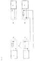
- FIG. 2 shows a data bus line 6 according to the invention with four transmitting and receiving components 1 to 4, the Connected to the bus line via nodes 1a to 4a are. It is a CAN bus whose technical properties essentially unchanged stay.
- the node 1a and 4a Terminating resistor 5r or 5l in bus line 6 placed.
- the contacts A1, A2 of the first switch A opened and contacts B1 and B2 of the second switch B and the contacts C1 and C2 of the third switch C closed.
- the contacts A1 and A2 of the first switch A and the contacts C1 and C2 of the third switch C closed while contacts B1 and B2 of the second Switch B are open.
- the contacts A1 and A2 of the first switch A and the Contacts B1 and B2 of the second switch B closed, while the contacts C1 and C2 of the third switch C are open so that the terminating resistors of this Nodes are not in the bus line.
- FIG. 3 shows the case in which between the nodes 1a and 2a an error 8 such as an interruption in the Bus line 6 occurs.
- the node 1a is now one Communication with the remaining nodes cut off.
- FIG 4 shows how this interference by appropriate Selection of the terminating resistors 5 can be avoided.
- the switches at node 1a are now in the positions brought as they were at node 4a in Figure 2, while the switches on node 2a take the positions take in node 1a in Figure 2.
- the nodes 3a and 4a are connected like nodes 2a and 3a in FIG. The data transfer is now carried out via the connection of nodes 1a and 4a.
- FIG. 5 shows the case in which the node 3a is complete is defective and by switching accordingly the remaining nodes are removed from the bus line system becomes.
- contacts A1 and A2 are in node 3a of switch A and contacts B1 and B2 of Switch B opened.
- node 2a takes the Switch positions of node 4a in Figure 2 and node 4a the switch positions of node 1a in FIG. 2.
- Node 1a is switched to pass according to FIG. 5, by its switches the positions of nodes 2a or Take 3a in Figure 2.
- the intact Components 1, 2 and 4 undisturbed via their nodes communicate with each other and the defective node is 3a isolated from its two neighboring nodes 2a and 4a.
- the described errors can of course be taken for granted occur between or at all nodes. They are recognized automatically by the components, as soon as a send signal addressed to a node is not acknowledged as received by this node. Only if there are two faults at the same time Regeneration is no longer possible.
Landscapes
- Engineering & Computer Science (AREA)
- Mechanical Engineering (AREA)
- Computer Networks & Wireless Communication (AREA)
- Signal Processing (AREA)
- Small-Scale Networks (AREA)
- Dc Digital Transmission (AREA)
Abstract
Description
Die Erfindung betrifft eine Datenbusleitung mit über Knoten angeschlossenen Sende- und Empfangskomponenten insbesondere für Fahrzeugsysteme.The invention relates to a data bus line with over Transmitting and receiving components connected to nodes especially for vehicle systems.
Es ist bekannt, in Fahrzeugen und anderen technischen Systemen Informationssignale über Busleitungen zu übertragen. Die einzelnen im System verteilten Komponenten, die Informationen austauschen müssen, liegen an einer gemeinsamen Busleitung. Die von einer Komponente ausgesendeten Informationen werden in der Weise adressiert, daß nur die entsprechende Zielkomponente diese Informationen erkennt und ausliest.It is known in vehicles and other technical Systems information signals via bus lines transfer. The individual distributed in the system Components that need to exchange information are on a common bus line. The one Information sent out in the component Addressed way that only the corresponding target component recognizes and reads this information.
Ein für die Übertragung in Fahrzeugsystemen geeigneter
Datenbus mit Sende- und Empfangskomponenten arbeitet
nach der Norm des CAN-Busses (Controller Area Network)
nach ISO/DIS (Draft International Standard) 11898. Bei
dieser Art von Datenübertragung werden binäre elektrische
Impulse (Bit), die in einem definierten
sequentiellen Muster als Datenprotokoll oder Datentelegramm
geordnet übertragen werden, zu vielfältigen
Zwecken über Datenaustausch zwischen einer auslösenden
und einer ausführenden Sende-/ und Empfangskomponente
an der Busleitung des Bussystems benutzt. Diese
Standardisierung mit einem Bus nach ISO/DIS 11898 ist
beispielhaft in Figur 6 gezeigt und besteht in einem in
gewissen Grenzen beliebig langen zweiadrigen Kabel 6
mit zwei Enden, die zur Gewährleistung einer technisch
zuverlässigen und störungsfreien Übertragung auch bei
hohen Frequenzen jeweils mit einem elektrischen Widerstand
5 abgeschlossen sind. Die Komponenten 1 bis 4
sind über jeweils einen Knoten 1a bis 4a mit der
Busleitung 6 verbunden.A suitable one for transmission in vehicle systems
Data bus works with transmitting and receiving components
according to the CAN bus (Controller Area Network) standard
according to ISO / DIS (Draft International Standard) 11898. bei
This type of data transmission will be binary electrical
Pulses (bits) defined in a
sequential pattern as data protocol or data telegram
orderly transferred, too diverse
Purposes of exchanging data between a triggering
and an executing transmission and reception component
used on the bus line of the bus system. This
Standardization with a bus according to ISO / DIS 11898 is
shown by way of example in FIG. 6 and consists of an in
certain limits two-wire cables of any
Ein Nachteil eines solchen bekannten Busses besteht darin, daß keine Redundanz vorhanden ist, die eine uneingeschränkte Kommunikation über den Bus auch dann noch gewährleistet, wenn die Busleitung an einer Stelle durchtrennt ist oder ein sonstiger Fehlerfall auftritt. Die beiden Komponenten, zwischen denen ein solcher Fehler auftritt, können dann nicht mehr störungsfrei oder überhaupt nicht mehr miteinander kommunizieren. Dies betrifft auch die jeweils weiter rechts oder links liegenden Komponenten. Dies ist insbesondere bei Systemen, bei denen hohe Anforderungen an die Übertragungssicherheit auch im Fehlerfall gestellt werden, nicht akzeptabel.There is a disadvantage of such a known bus in that there is no redundancy, the one unrestricted communication via the bus even then still guaranteed if the bus line at one point is severed or another error occurs. The two components between which one Errors occur, can then no longer be trouble-free or no longer communicate with each other. This also applies to those on the right or left lying components. This is particularly the case with Systems with high demands on transmission security also be made in the event of an error, unacceptable.
Der Erfindung liegt deshalb die Aufgabe zugrunde, eine Datenbusleitung mit über Knoten angeschlossenen Sende- und Empfangskomponenten insbesondere für Fahrzeugsysteme zu schaffen, bei der die Übertragungssicherheit auch im Falle eines Durchtrennens des Busses an einer Stelle aufrechterhalten bleibt.The invention is therefore based on the object Data bus line with transmit and Receiving components, in particular for vehicle systems to create at which the transmission security even if the bus is cut at one Position is maintained.
Gelöst wird diese Aufgabe mit einer Datenbusleitung der eingangs genannten Art dadurch, daß an jedem Knoten ein Abschlußwiderstand in die Busleitung schaltbar ist und beiderseits des Abschlußwiderstandes jeweils ein unabhängig betätigbarer erster bzw. zweiter Schalter liegt, mit dem die Busleitung beiderseits des Abschlußwiderstandes unterbrochen werden kann. This task is solved with a data bus line type mentioned in that at each node Termination resistor is switchable in the bus line and on both sides of the terminating resistor independently operated first or second switch is with which the bus line on both sides of the terminating resistor can be interrupted.
Die Unteransprüche haben vorteilhafte Weiterbildungen der Erfindung zum Inhalt.The subclaims have advantageous developments the content of the invention.
Danach ist an jedem Knoten insbesondere ein dritter Schalter vorgesehen, mit dem durch Schließen der Abschlußwiderstand in die Busleitung gelegt wird.After that there is in particular a third at each node Switch provided by closing the Termination resistor is placed in the bus line.
Schließlich verbindet die Busleitung die Knoten vorzugsweise ringförmig miteinander, wobei ein Leitungsstück zwischen zwei benachbarten Knoten durch entsprechende Öffnung des ersten bzw. zweiten Schalters an diesen Knoten offen ist.Finally, the bus line preferably connects the nodes ring-shaped with each other, with a line piece between two neighboring nodes by corresponding ones Opening of the first or second switch this node is open.
Weitere Einzelheiten, Merkmale und Vorteile ergeben sich aus der nachfolgenden Beschreibung einer bevorzugten Ausführungsform anhand der Zeichnung. Es zeigt:
- Fig. 1
- ein Prinzipschaltbild eines erfindungsgemäßen Knotens,
- Fig. 2
- ein Prinzipschaltbild einer erfindungsgemäßen Datenbusleitung,
- Fig. 3
- die Datenbusleitung in gestörtem Zustand,
- Fig. 4
- die Datenbusleitung in wiederhergestelltem Zustand,
- Fig. 5
- die Datenbusleitung mit einem gestörten Knoten und
- Fig. 6
- eine Datenbusleitung gemäß dem Stand der Technik (CAN-Bus).
- Fig. 1
- 2 shows a basic circuit diagram of a node according to the invention,
- Fig. 2
- 2 shows a basic circuit diagram of a data bus line according to the invention,
- Fig. 3
- the data bus line in a faulty state,
- Fig. 4
- the data bus line in a restored state,
- Fig. 5
- the data bus line with a faulty node and
- Fig. 6
- a data bus line according to the prior art (CAN bus).
Figur 1 zeigt einen in eine Busleitung 6 geschalteten
Knoten. Unter "Knoten" soll in diesem Zusammenhang die
Verbindungsschaltung einer Sende- und
Empfangskomponente 1, 2, 3, 4 (siehe Figur 2) mit der
eigentlichen Busleitung 6 verstanden werden. Jede
Komponente 1, 2, 3, 4, die über die Busleitung 6 mit
anderen Komponenten Daten austauschen soll, ist somit
über einen Knoten 1a, 2a, 3a, 4a mit der Busleitung 6
verbunden.Figure 1 shows a connected in a
Der Knoten weist gemäß Figur 1 einen ersten und einen
zweiten Schalter A, B auf. Mit den Schaltern, die hier
zur Erleichterung des Verständnisses als Relais dargestellt
sind, kann die Busleitung durch Öffnen der
Kontakte A1, A2 sowie B1, B2 unterbrochen werden.
Zwischen den beiden Schaltern befindet sich ein dritter
Schalter C mit Schaltkontakten C1, C2, mit denen durch
Schließen ein Abschlußwiderstand 5 in die Busleitung
gelegt werden kann. Die Sende- und Empfangskomponente
ist über Anschlüsse 6a zwischen den Kontakten des
ersten und zweiten Schalters A, B in die Busleitung
eingeschaltet.According to FIG. 1, the node has a first and a
second switch A, B on. With the switches here
Shown as a relay for ease of understanding
the bus line can be opened by opening the
Contacts A1, A2 and B1, B2 are interrupted.
There is a third between the two switches
Switch C with switch contacts C1, C2, through which
Connect a terminating
Figur 2 zeigt eine erfindungsgemäße Datenbusleitung 6
mit vier Sende- und Empfangskomponenten 1 bis 4, die
über Knoten 1a bis 4a mit der Busleitung verbunden
sind. Es handelt sich hierbei um einen CAN-Bus, dessen
technische Eigenschaften im wesentlichen unverändert
bleiben.FIG. 2 shows a
Im dargestellten Fall wird an den Knoten 1a und 4a der
Abschlußwiderstand 5r bzw. 5l in die Busleitung 6
gelegt. Am Knoten 1a sind die Kontakte A1, A2 des
ersten Schalters A geöffnet und die Kontakte B1 und B2
des zweiten Schalters B sowie die Kontakte C1 und C2
des dritten Schalters C geschlossen. Am Knoten 4a sind
hingegen die Kontakte A1 und A2 des ersten Schalters A
und die Kontakte C1 und C2 des dritten Schalters C
geschlossen, während die Kontakte B1 und B2 des zweiten
Schalters B geöffnet sind. An den Knoten 2a und 3a sind
die Kontakte A1 und A2 des ersten Schalters A und die
Kontakte B1 und B2 des zweiten Schalters B geschlossen,
während die Kontakte C1 und C2 des dritten Schalters C
geöffnet sind, so daß die Abschlußwiderstände dieser
Knoten nicht in der Busleitung liegen.In the case shown, the
Figur 3 zeigt den Fall, in dem zwischen den Knoten 1a
und 2a ein Fehler 8 wie z.B. eine Unterbrechung in der
Busleitung 6 auftritt. Der Knoten 1a ist nun von einer
Kommunikation mit den übrigen Knoten abgeschnitten.Figure 3 shows the case in which between the
Figur 4 zeigt, wie diese Störung durch entsprechende
Auswahl der Abschlußwiderstände 5 umgangen werden kann.
Die Schalter am Knoten 1a werden nun in die Stellungen
gebracht, wie sie sich am Knoten 4a in Figur 2 befanden,
während die Schalter am Knoten 2a die Stellungen
im Knoten 1a in Figur 2 einnehmen. Die Knoten 3a
und 4a sind wie die Knoten 2a und 3a in Figur 2 geschaltet.
Die Datenübertragung erfolgt somit nun über
die Verbindung der Knoten 1a und 4a.Figure 4 shows how this interference by appropriate
Selection of the terminating
Figur 5 zeigt den Fall, in dem der Knoten 3a vollständig
defekt ist und durch entsprechende Umschaltung
der übrigen Knoten aus dem Busleitungssystem entfernt
wird. Dazu werden im Knoten 3a die Kontakte A1 und A2
des Schalters A und die Kontakte B1 und B2 des
Schalters B geöffnet. Ferner nimmt Knoten 2a die
Schalterstellungen von Knoten 4a in Figur 2 und Knoten
4a die Schalterstellungen von Knoten 1a in Figur 2 ein.
Knoten 1a wird gemäß Figur 5 auf Durchgang geschaltet,
indem seine Schalter die Stellungen der Knoten 2a oder
3a in Figur 2 einnehmen. Somit können die intakten
Komponenten 1, 2 und 4 über ihre Knoten ungestört
miteinander kommunizieren und der defekte Knoten 3a ist
von seinen beiden Nachbarknoten 2a und 4a isoliert. Figure 5 shows the case in which the
Insgesamt wird also eine virtuelle Ring-Busübertragung realisiert, mit der Leitungsfehler umgangen und defekte Komponenten unwirksam gemacht werden können.Overall, there will be a virtual ring bus transmission realized with the line errors bypassed and broken Components can be rendered ineffective.
Die beschriebenen Fehlerfälle können sich selbstverständlich zwischen bzw. an allen Knoten ereignen. Sie werden von den Komponenten selbsttätig erkannt, sobald ein an einen Knoten adressiertes Sendesignal nicht von diesem Knoten als empfangen quittiert wird. Erst wenn gleichzeitig zwei Störungen der beschriebenen Art auftreten, ist eine Regeneration nicht mehr möglich.The described errors can of course be taken for granted occur between or at all nodes. They are recognized automatically by the components, as soon as a send signal addressed to a node is not acknowledged as received by this node. Only if there are two faults at the same time Regeneration is no longer possible.
Claims (3)
Applications Claiming Priority (2)
| Application Number | Priority Date | Filing Date | Title |
|---|---|---|---|
| DE19733760 | 1997-08-05 | ||
| DE19733760A DE19733760C2 (en) | 1997-08-05 | 1997-08-05 | Data bus line with transmission and reception components |
Publications (3)
| Publication Number | Publication Date |
|---|---|
| EP0895899A2 true EP0895899A2 (en) | 1999-02-10 |
| EP0895899A3 EP0895899A3 (en) | 2000-04-19 |
| EP0895899B1 EP0895899B1 (en) | 2003-11-12 |
Family
ID=7837995
Family Applications (1)
| Application Number | Title | Priority Date | Filing Date |
|---|---|---|---|
| EP98107502A Expired - Lifetime EP0895899B1 (en) | 1997-08-05 | 1998-04-24 | Data bus line with data transmitting/receiving components |
Country Status (2)
| Country | Link |
|---|---|
| EP (1) | EP0895899B1 (en) |
| DE (2) | DE19733760C2 (en) |
Cited By (5)
| Publication number | Priority date | Publication date | Assignee | Title |
|---|---|---|---|---|
| EP1044851A2 (en) * | 1999-04-12 | 2000-10-18 | MaK System Gesellschaft mbH | Apparatus for a power ring |
| EP1309043A2 (en) * | 2001-10-31 | 2003-05-07 | Yazaki Corporation | Plug shaped terminating resistance device |
| FR2916874A1 (en) * | 2007-06-04 | 2008-12-05 | Nexter Systems Sa | DEVICE FOR CONNECTING COMPONENTS ON A BUS LINE, BUS LINE AND METHODS FOR REGENERATING A BUS LINE USING SUCH A CONNECTING DEVICE |
| WO2013059495A1 (en) * | 2011-10-18 | 2013-04-25 | Schneider Electric Buildings, Llc | Self-healing communications network |
| EP2817923B1 (en) * | 2012-02-24 | 2021-01-20 | Rheinmetall Landsysteme GmbH | Computer network with a ring bus connection |
Families Citing this family (7)
| Publication number | Priority date | Publication date | Assignee | Title |
|---|---|---|---|---|
| DE19946993A1 (en) * | 1999-09-30 | 2001-04-19 | Infineon Technologies Ag | Protection circuit for an access-restricted bus system network |
| DE20116380U1 (en) | 2001-10-05 | 2003-02-13 | Siemens AG, 80333 München | CAN-bus for control of telecommunication system, has total network impedance reduced by parallel circuiting of termination impedances |
| DE10310302B4 (en) * | 2003-03-10 | 2007-05-16 | Knorr Bremse Systeme | Initialization method for a data bus arrangement |
| DE10324724A1 (en) * | 2003-05-30 | 2004-12-16 | Wabco Gmbh & Co.Ohg | Control device with redundant CAN data bus e.g. for communication systems, has additional CAN data bus segment as redundant data bus segment provided between data bus terminals |
| JP2011076903A (en) * | 2009-09-30 | 2011-04-14 | Sanyo Electric Co Ltd | Battery apparatus and electric vehicle |
| DE102010044892A1 (en) * | 2010-09-09 | 2012-03-15 | Novar Gmbh | Danger alarm system with two data transmission speeds |
| DE102010046152B3 (en) | 2010-09-21 | 2011-12-15 | Rheinmetall Landsysteme Gmbh | Plant with n - mechanically interconnected facilities |
Citations (3)
| Publication number | Priority date | Publication date | Assignee | Title |
|---|---|---|---|---|
| EP0419712A1 (en) * | 1989-09-28 | 1991-04-03 | Siemens Aktiengesellschaft | Decoupling device for a bus communication system |
| EP0491179A1 (en) * | 1990-12-11 | 1992-06-24 | Bayerische Motoren Werke Aktiengesellschaft | Linear data bus |
| EP0712267A2 (en) * | 1994-11-10 | 1996-05-15 | Weidmüller Interface GmbH & Co. | Modular control equipment with field bus integrated connection |
-
1997
- 1997-08-05 DE DE19733760A patent/DE19733760C2/en not_active Expired - Fee Related
-
1998
- 1998-04-24 EP EP98107502A patent/EP0895899B1/en not_active Expired - Lifetime
- 1998-04-24 DE DE59810130T patent/DE59810130D1/en not_active Expired - Fee Related
Patent Citations (3)
| Publication number | Priority date | Publication date | Assignee | Title |
|---|---|---|---|---|
| EP0419712A1 (en) * | 1989-09-28 | 1991-04-03 | Siemens Aktiengesellschaft | Decoupling device for a bus communication system |
| EP0491179A1 (en) * | 1990-12-11 | 1992-06-24 | Bayerische Motoren Werke Aktiengesellschaft | Linear data bus |
| EP0712267A2 (en) * | 1994-11-10 | 1996-05-15 | Weidmüller Interface GmbH & Co. | Modular control equipment with field bus integrated connection |
Cited By (12)
| Publication number | Priority date | Publication date | Assignee | Title |
|---|---|---|---|---|
| EP1044851A2 (en) * | 1999-04-12 | 2000-10-18 | MaK System Gesellschaft mbH | Apparatus for a power ring |
| EP1044851A3 (en) * | 1999-04-12 | 2001-04-11 | Rheinmetall Landsysteme GmbH | Apparatus for a power ring |
| US6552443B1 (en) | 1999-04-12 | 2003-04-22 | Rheinmetall Landsysteme Gmbh | Power ring |
| EP1309043A2 (en) * | 2001-10-31 | 2003-05-07 | Yazaki Corporation | Plug shaped terminating resistance device |
| EP1309043A3 (en) * | 2001-10-31 | 2003-06-04 | Yazaki Corporation | Plug shaped terminating resistance device |
| US6994562B2 (en) | 2001-10-31 | 2006-02-07 | Yazaki Corporation | Apparatus for multiplex communication |
| FR2916874A1 (en) * | 2007-06-04 | 2008-12-05 | Nexter Systems Sa | DEVICE FOR CONNECTING COMPONENTS ON A BUS LINE, BUS LINE AND METHODS FOR REGENERATING A BUS LINE USING SUCH A CONNECTING DEVICE |
| EP2001169A1 (en) | 2007-06-04 | 2008-12-10 | NEXTER Systems | Device for connecting components to a BUS line, BUS line and methods for regenerating a BUS line implementing such a connection device |
| WO2013059495A1 (en) * | 2011-10-18 | 2013-04-25 | Schneider Electric Buildings, Llc | Self-healing communications network |
| US9313042B2 (en) | 2011-10-18 | 2016-04-12 | Schneider Electric Buildings, Llc | Self-healing communications network |
| US9497038B2 (en) | 2011-10-18 | 2016-11-15 | Schneider Electric Buildings, Llc | Self-healing communications network |
| EP2817923B1 (en) * | 2012-02-24 | 2021-01-20 | Rheinmetall Landsysteme GmbH | Computer network with a ring bus connection |
Also Published As
| Publication number | Publication date |
|---|---|
| DE19733760C2 (en) | 1999-06-10 |
| DE19733760A1 (en) | 1999-03-04 |
| EP0895899B1 (en) | 2003-11-12 |
| DE59810130D1 (en) | 2003-12-18 |
| EP0895899A3 (en) | 2000-04-19 |
Similar Documents
| Publication | Publication Date | Title |
|---|---|---|
| DE4404962C2 (en) | Method and arrangement for configuring functional units in a master-slave arrangement | |
| EP0895899B1 (en) | Data bus line with data transmitting/receiving components | |
| DE4229175A1 (en) | Network interface | |
| DE10207529A1 (en) | Local network, in particular an Ethernet network with redundancy properties and a coupling device for such a network | |
| DE3416990C2 (en) | Test system for a signal transmission system | |
| DE19646016C2 (en) | Method for the equivalent switching of transmission devices for the bidirectional transmission of ATM cells | |
| EP0448734A1 (en) | Circuit arrangement for the routine testing of the interface between transmission groups and the switching network of a PCM telecommunications exchange | |
| EP1010303A1 (en) | Communication device for transmitting message signals | |
| DE19515194A1 (en) | Communication network and control device for vehicle | |
| EP0263246B1 (en) | Explosion-protected multiplexer | |
| DE3842762C2 (en) | ||
| DE102005056284A1 (en) | Method of making a network formed of buses of the CAN type, network and devices with this network | |
| DE4215945C1 (en) | ||
| EP0792078A1 (en) | Actuator-sensor interface system | |
| DE3800977C2 (en) | ||
| DE19639352C2 (en) | Sensor-actuator bus system with subsystems connected via specially trained repeaters | |
| EP1016238A1 (en) | Redundancy system with "1:n" and "1:1" redundancy for a asn-system | |
| DE10207527A1 (en) | Local network, in particular Ethernet network, with redundancy properties and coupling device for such a network | |
| DE3830321C2 (en) | ||
| EP1972107A1 (en) | Protection or control-system appliance | |
| CH649744A5 (en) | Device for transmitting information for remotely controlling railway signalling systems | |
| EP1465358A2 (en) | Data communication unit for a set of railway wagons | |
| DE102010046152B3 (en) | Plant with n - mechanically interconnected facilities | |
| EP0235649A1 (en) | Circuit arrangement for serial data transmission between several stations | |
| DE19714761A1 (en) | Data communication connection in a hierarchical communication network with bus, which is operated according to a polling protocol |
Legal Events
| Date | Code | Title | Description |
|---|---|---|---|
| PUAI | Public reference made under article 153(3) epc to a published international application that has entered the european phase |
Free format text: ORIGINAL CODE: 0009012 |
|
| AK | Designated contracting states |
Kind code of ref document: A2 Designated state(s): DE FR GB NL SE |
|
| AX | Request for extension of the european patent |
Free format text: AL;LT;LV;MK;RO;SI |
|
| PUAL | Search report despatched |
Free format text: ORIGINAL CODE: 0009013 |
|
| RIC1 | Information provided on ipc code assigned before grant |
Free format text: 7B 60R 16/02 A, 7H 04L 12/40 B |
|
| AK | Designated contracting states |
Kind code of ref document: A3 Designated state(s): AT BE CH CY DE DK ES FI FR GB GR IE IT LI LU MC NL PT SE |
|
| AX | Request for extension of the european patent |
Free format text: AL;LT;LV;MK;RO;SI |
|
| 17P | Request for examination filed |
Effective date: 20000518 |
|
| AKX | Designation fees paid |
Free format text: DE FR GB NL SE |
|
| RAP1 | Party data changed (applicant data changed or rights of an application transferred) |
Owner name: RHEINMETALL LANDSYSTEME GMBH |
|
| 17Q | First examination report despatched |
Effective date: 20020424 |
|
| GRAH | Despatch of communication of intention to grant a patent |
Free format text: ORIGINAL CODE: EPIDOS IGRA |
|
| GRAS | Grant fee paid |
Free format text: ORIGINAL CODE: EPIDOSNIGR3 |
|
| GRAA | (expected) grant |
Free format text: ORIGINAL CODE: 0009210 |
|
| AK | Designated contracting states |
Kind code of ref document: B1 Designated state(s): DE FR GB NL SE |
|
| REG | Reference to a national code |
Ref country code: GB Ref legal event code: FG4D Free format text: NOT ENGLISH |
|
| REF | Corresponds to: |
Ref document number: 59810130 Country of ref document: DE Date of ref document: 20031218 Kind code of ref document: P |
|
| REG | Reference to a national code |
Ref country code: SE Ref legal event code: TRGR |
|
| GBT | Gb: translation of ep patent filed (gb section 77(6)(a)/1977) |
Effective date: 20040213 |
|
| ET | Fr: translation filed | ||
| PLBE | No opposition filed within time limit |
Free format text: ORIGINAL CODE: 0009261 |
|
| STAA | Information on the status of an ep patent application or granted ep patent |
Free format text: STATUS: NO OPPOSITION FILED WITHIN TIME LIMIT |
|
| 26N | No opposition filed |
Effective date: 20040813 |
|
| PGFP | Annual fee paid to national office [announced via postgrant information from national office to epo] |
Ref country code: NL Payment date: 20050412 Year of fee payment: 8 |
|
| PG25 | Lapsed in a contracting state [announced via postgrant information from national office to epo] |
Ref country code: NL Free format text: LAPSE BECAUSE OF NON-PAYMENT OF DUE FEES Effective date: 20061101 |
|
| NLV4 | Nl: lapsed or anulled due to non-payment of the annual fee |
Effective date: 20061101 |
|
| PGFP | Annual fee paid to national office [announced via postgrant information from national office to epo] |
Ref country code: SE Payment date: 20070412 Year of fee payment: 10 |
|
| PGFP | Annual fee paid to national office [announced via postgrant information from national office to epo] |
Ref country code: GB Payment date: 20070426 Year of fee payment: 10 |
|
| PGFP | Annual fee paid to national office [announced via postgrant information from national office to epo] |
Ref country code: FR Payment date: 20070416 Year of fee payment: 10 |
|
| EUG | Se: european patent has lapsed | ||
| GBPC | Gb: european patent ceased through non-payment of renewal fee |
Effective date: 20080424 |
|
| REG | Reference to a national code |
Ref country code: FR Ref legal event code: ST Effective date: 20081231 |
|
| PG25 | Lapsed in a contracting state [announced via postgrant information from national office to epo] |
Ref country code: FR Free format text: LAPSE BECAUSE OF NON-PAYMENT OF DUE FEES Effective date: 20080430 |
|
| PG25 | Lapsed in a contracting state [announced via postgrant information from national office to epo] |
Ref country code: GB Free format text: LAPSE BECAUSE OF NON-PAYMENT OF DUE FEES Effective date: 20080424 |
|
| PGFP | Annual fee paid to national office [announced via postgrant information from national office to epo] |
Ref country code: DE Payment date: 20090422 Year of fee payment: 12 |
|
| PG25 | Lapsed in a contracting state [announced via postgrant information from national office to epo] |
Ref country code: SE Free format text: LAPSE BECAUSE OF NON-PAYMENT OF DUE FEES Effective date: 20080425 |
|
| PG25 | Lapsed in a contracting state [announced via postgrant information from national office to epo] |
Ref country code: DE Free format text: LAPSE BECAUSE OF NON-PAYMENT OF DUE FEES Effective date: 20101103 |