EP0895360A2 - Optical incremental encoder - Google Patents
Optical incremental encoder Download PDFInfo
- Publication number
- EP0895360A2 EP0895360A2 EP98105683A EP98105683A EP0895360A2 EP 0895360 A2 EP0895360 A2 EP 0895360A2 EP 98105683 A EP98105683 A EP 98105683A EP 98105683 A EP98105683 A EP 98105683A EP 0895360 A2 EP0895360 A2 EP 0895360A2
- Authority
- EP
- European Patent Office
- Prior art keywords
- light
- increment
- rotation
- axis
- wheel
- Prior art date
- Legal status (The legal status is an assumption and is not a legal conclusion. Google has not performed a legal analysis and makes no representation as to the accuracy of the status listed.)
- Withdrawn
Links
- 230000003287 optical effect Effects 0.000 title claims description 27
- 238000011156 evaluation Methods 0.000 description 11
- 230000008901 benefit Effects 0.000 description 8
- 238000001514 detection method Methods 0.000 description 8
- 230000010363 phase shift Effects 0.000 description 6
- 238000010586 diagram Methods 0.000 description 4
- 238000004519 manufacturing process Methods 0.000 description 4
- 238000000034 method Methods 0.000 description 3
- 230000008569 process Effects 0.000 description 3
- 230000005540 biological transmission Effects 0.000 description 2
- 230000009467 reduction Effects 0.000 description 2
- 238000011161 development Methods 0.000 description 1
- 230000018109 developmental process Effects 0.000 description 1
- 238000001208 nuclear magnetic resonance pulse sequence Methods 0.000 description 1
- 230000000737 periodic effect Effects 0.000 description 1
- 238000003825 pressing Methods 0.000 description 1
- 230000004044 response Effects 0.000 description 1
Images


Classifications
-
- G—PHYSICS
- G01—MEASURING; TESTING
- G01D—MEASURING NOT SPECIALLY ADAPTED FOR A SPECIFIC VARIABLE; ARRANGEMENTS FOR MEASURING TWO OR MORE VARIABLES NOT COVERED IN A SINGLE OTHER SUBCLASS; TARIFF METERING APPARATUS; MEASURING OR TESTING NOT OTHERWISE PROVIDED FOR
- G01D5/00—Mechanical means for transferring the output of a sensing member; Means for converting the output of a sensing member to another variable where the form or nature of the sensing member does not constrain the means for converting; Transducers not specially adapted for a specific variable
- G01D5/26—Mechanical means for transferring the output of a sensing member; Means for converting the output of a sensing member to another variable where the form or nature of the sensing member does not constrain the means for converting; Transducers not specially adapted for a specific variable characterised by optical transfer means, i.e. using infrared, visible, or ultraviolet light
- G01D5/32—Mechanical means for transferring the output of a sensing member; Means for converting the output of a sensing member to another variable where the form or nature of the sensing member does not constrain the means for converting; Transducers not specially adapted for a specific variable characterised by optical transfer means, i.e. using infrared, visible, or ultraviolet light with attenuation or whole or partial obturation of beams of light
- G01D5/34—Mechanical means for transferring the output of a sensing member; Means for converting the output of a sensing member to another variable where the form or nature of the sensing member does not constrain the means for converting; Transducers not specially adapted for a specific variable characterised by optical transfer means, i.e. using infrared, visible, or ultraviolet light with attenuation or whole or partial obturation of beams of light the beams of light being detected by photocells
- G01D5/36—Forming the light into pulses
- G01D5/363—Direction discrimination
-
- G—PHYSICS
- G01—MEASURING; TESTING
- G01D—MEASURING NOT SPECIALLY ADAPTED FOR A SPECIFIC VARIABLE; ARRANGEMENTS FOR MEASURING TWO OR MORE VARIABLES NOT COVERED IN A SINGLE OTHER SUBCLASS; TARIFF METERING APPARATUS; MEASURING OR TESTING NOT OTHERWISE PROVIDED FOR
- G01D5/00—Mechanical means for transferring the output of a sensing member; Means for converting the output of a sensing member to another variable where the form or nature of the sensing member does not constrain the means for converting; Transducers not specially adapted for a specific variable
- G01D5/26—Mechanical means for transferring the output of a sensing member; Means for converting the output of a sensing member to another variable where the form or nature of the sensing member does not constrain the means for converting; Transducers not specially adapted for a specific variable characterised by optical transfer means, i.e. using infrared, visible, or ultraviolet light
- G01D5/32—Mechanical means for transferring the output of a sensing member; Means for converting the output of a sensing member to another variable where the form or nature of the sensing member does not constrain the means for converting; Transducers not specially adapted for a specific variable characterised by optical transfer means, i.e. using infrared, visible, or ultraviolet light with attenuation or whole or partial obturation of beams of light
- G01D5/34—Mechanical means for transferring the output of a sensing member; Means for converting the output of a sensing member to another variable where the form or nature of the sensing member does not constrain the means for converting; Transducers not specially adapted for a specific variable characterised by optical transfer means, i.e. using infrared, visible, or ultraviolet light with attenuation or whole or partial obturation of beams of light the beams of light being detected by photocells
- G01D5/347—Mechanical means for transferring the output of a sensing member; Means for converting the output of a sensing member to another variable where the form or nature of the sensing member does not constrain the means for converting; Transducers not specially adapted for a specific variable characterised by optical transfer means, i.e. using infrared, visible, or ultraviolet light with attenuation or whole or partial obturation of beams of light the beams of light being detected by photocells using displacement encoding scales
- G01D5/3473—Circular or rotary encoders
-
- H—ELECTRICITY
- H03—ELECTRONIC CIRCUITRY
- H03M—CODING; DECODING; CODE CONVERSION IN GENERAL
- H03M1/00—Analogue/digital conversion; Digital/analogue conversion
- H03M1/12—Analogue/digital converters
- H03M1/22—Analogue/digital converters pattern-reading type
- H03M1/24—Analogue/digital converters pattern-reading type using relatively movable reader and disc or strip
- H03M1/28—Analogue/digital converters pattern-reading type using relatively movable reader and disc or strip with non-weighted coding
- H03M1/30—Analogue/digital converters pattern-reading type using relatively movable reader and disc or strip with non-weighted coding incremental
- H03M1/301—Constructional details of parts relevant to the encoding mechanism, e.g. pattern carriers, pattern sensors
Definitions
- the invention relates to an optical increment encoder the genus of the main claim.
- the one Have knobs of different switching positions can take.
- There are at least 2 LEDs and associated ones Light receiver provided, the light receiver emit signal pulse sequences when the rotary control is actuated, which are phase-shifted by 90 ° depending on the direction of rotation.
- the optical incremental encoder according to the invention with the features the main claim has the advantage that not an independent component with an axis of rotation for mounting the rotational movement of the increment wheel on a circuit board is to be provided so that when the increment wheel is actuated no mechanical forces on the circuit board be transmitted. This way the circuit board not mechanically stressed by operating the increment wheel.
- Another advantage is that the capture no mechanical stress from increment wheel settings required as they are non-contact via light receivers he follows.
- Another advantage is that the light receiver with a rotation of the increment wheel depending on the Direction of rotation alternately lighter and darker Detect areas. Hence a determination of Direction of rotation of the actuated increment wheel possible.
- Light transmitter and light receiver each as a structural light transmitter / receiver unit train, which means space, manufacturing costs and costs can be saved.
- the increment wheel has two ring-shaped reflectors concentric to the axis of rotation, which are spaced differently from the axis of rotation are that each reflector is exactly one of the two light transmitters and exactly one of the two light receivers are assigned the respective light transmitter light on the assigned to it
- the reflector emits and the associated light receiver the light reflected by this reflector of the associated Light transmitter receives that the reflectors are concentric to the Rotary axis each have a coding track and that on the Coding traces the lighter areas and the darker areas are arranged alternately.
- the reflectors are concentric to the Rotary axis each have a coding track and that on the Coding traces the lighter areas and the darker areas are arranged alternately.
- Another advantage is that the light transmitting / receiving units on a common radial to the axis of rotation lie and that the coding tracks out of phase with each other are arranged on the increment wheel. In this way can be used to determine the direction of rotation when actuated of the increment wheel required phase-shifted Detection of the reflected light at the light receivers Realize particularly easily and precisely.
- the two coding tracks are the same Have number of lighter areas and darker areas. This enables the production of the coding tracks simplify and standardize.
- the increment wheel exactly one ring-shaped reflector concentric to the axis of rotation has that the reflector, the two light transmitters and the two light receivers are assigned, the two Light transmitter emit light on the reflector and the two The light receiver reflects the light from the reflector each assigned light transmitter receive that the Reflector has a coding track concentric to the axis of rotation and that the lighter areas and the darker areas are arranged alternately. To this In this way, one coding track can be saved, as a result of which Manufacturing expenditure for the optical increment encoder further is reduced.
- a phase-shifted detection of the reflected one Light through the light receiver can also be achieved be arranged so that the light transmitter and the light receiver are that the light receiver is not on at the same time same radial lines reflected to the axis of rotation of the increment wheel Detect light. This way too thus the for determining the direction of rotation when the Increment wheel required phase-shifted detection of the reflected light at the light receivers and implement precisely.
- the increment wheel is centric Axis of rotation has a bore and that in the bore preferably illuminable push button is arranged via which a pressure contact can be actuated. That way the functionality of the increment wheel increased so that over the push button of the increment wheel, for example, an on or Switch is feasible. Since no annoying, with the axis connected to the circuit board is present, can the pressure contact easily on the circuit board Arrange below the pushbutton. Through the hole is also prevented by pressing the pushbutton the reflectors are moved so that when the Push button a mechanical stress on the reflectors of the increment wheel is avoided.
- the functionality of the pushbutton is also increased because it also acts as an axis for the rotary movement of the increment wheel serves.
- the pushbutton is designed to be illuminated is. This will make operation more convenient for the user relieved especially at night.
- Another advantage is that the lighter areas and the darker areas of a coding track are the same are great. In this way, the production of the coding tracks simplify.
- FIG. 1 shows an optical device according to the invention Increment encoder according to a first embodiment
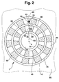
- figure 2 an optical incremental encoder according to the invention according to a second embodiment
- Figure 3 shows an inventive optical incremental encoder according to a third embodiment
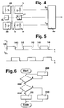
- Figure 4 is a block diagram of an inventive optical incremental encoder
- Figure 5 shows a course of Output signals of the light receiver of the optical according to the invention Increment encoder
- Figure 6 is a flow chart for the Evaluation of the output signals of the light receiver in one Evaluation circuit.
- 1 denotes an optical increment encoder, for example for the volume setting of a car radio can be used, but generally for the incremental Setting values of any functions on any electrical devices.
- the optical increment encoder 1 comprises an increment wheel 10 arranged on a device cap 85 an axis of rotation 5 which is perpendicular to the device cap 85 on the Device cap 85 is arranged.
- the increment wheel 10 is around the axis of rotation 5 is rotatably supported on the device cap 85.
- the reflectors 35, 40 are each as coding tracks formed concentrically to the axis of rotation 5 with alternately lighter areas 45 and darker areas Surfaces 50 formed.
- the lighter areas are 45 and the darker areas 50 are the same as a coding track 35, 40 large.
- the two coding tracks 35, 40 have the same number of lighter areas 45 and darker areas 50 on.
- the alternation of the lighter areas 45 with the darker areas 50 are each in tangential, not realized in the radial direction.
- the two coding tracks 35, 40 are in the exemplary embodiment according to FIG. 1 by 90 ° arranged out of phase with each other on the increment wheel 10. Other phase shifts are also possible except for a phase shift of 0 or 180 °. With the latter two phase shift angles detection of the direction of rotation when actuated of the increment wheel 10 no longer ensure.
- On a Radials 65 to the axis of rotation 5 are two light transmitting / receiving units 55, 60, each as a structural unit a light transmitter 25, 30 and a light receiver 15, 20 are trained.
- a first light transmitter 25 thus forms a first light receiver 15 a first light transmitting / receiving unit 55 and a second light transmitter 30 and one second light receivers 20 form a second light transmission / reception unit 60.
- the first light transmitting / receiving unit 55 is further away from the axis of rotation 5 than the second Light sending / receiving unit 60.
- the first light sending / receiving unit 55 is covered by the first reflector 35 and the second light transmitting / receiving unit 60 covered by the second reflector 40.
- the first light transmitter / receiver unit 55 is thus assigned to the first reflector 35, and the second light transmitting / receiving unit is 60 assigned to the second reflector 40.
- the two light transmitting / receiving units 55, 60 are on the increment wheel 10 facing side on a not shown in Figure 1 Printed circuit board arranged on the the increment wheel 10 facing away from the device cap 85. About corresponding Breakthroughs in the device cap 85 are the two Light transmitting / receiving units 55, 60 on the device cap 85 accessible.
- the first reflector 35 is the first Assigned light transmitter 25 and the first light receiver 15
- the second reflector 40 is the second light transmitter 30 and the second light receiver 20 assigned.
- the one for each Reflector 35, 40 associated light transmitter 25, 30 emits light onto this reflector 35, 40. There it will be reflected and from that assigned to the respective reflector 35, 40 Light receiver 15, 20 received.
- the increment wheel 10 In the position of the increment wheel 10 according to FIG. 1 receives the first Light receiver 15 reflected from a lighter surface 45 Light, whereas due to the phase shift of the two coding tracks 35, 40 by 90 ° the second light receiver 20 receives light reflected from a darker surface 50.
- the increment wheel 10 can also be centered on the axis of rotation 5 have a bore 70, wherein in the bore 70 a Push button 75 is arranged, via which a pressure contact, for example to switch on / off the device or the special one operable by the increment wheel 10 function is.
- the increment wheel 10 is preferably around cylindrical push button 75 mounted on the device cap 85.
- Figure 2 is another embodiment of the invention optical incremental encoder 1 shown, wherein Identical reference symbols denote identical elements.
- the difference the coding tracks are for the exemplary embodiment according to FIG. 1 35, 40 not out of phase with each other.
- the first and the second light transmitting / receiving unit 55, 60 not on the same radial to the axis of rotation 5. Rather, the first light transmission / reception unit 55 is on a first radial 65 and the second light transmitting / receiving unit 60 arranged on a second radial 66.
- the reflectors 35, 40 are assigned Light transmitter 25, 30 and light receiver 15, 20 arranged so that each of the two light receivers 15, 20 at a different Radials 65, 66 to the axis of rotation 5 of the increment wheel 10 reflected light detected.
- the two radials 65, 66 to the axis of rotation 5 for the arrangement of the light transmitting / receiving units 55, 60 according to FIG. 2 are chosen so that the corresponding light receiver 15, 20 the brighter Surfaces 45 and the darker surfaces 50 with a phase shift detect from 90 °.
- the increment wheel takes 10 according to Figure 2 a current position in which the first light receiver 15 detects a lighter area 45 and the second light receiver 20 has a darker area 50.
- FIG. 3 is another embodiment of the invention optical incremental encoder 1 shown, wherein Identical reference symbols denote identical elements.
- the increment wheel 10 in the embodiment 3 exactly one reflector 35. It is also the first light transmitter / receiver unit 55 as well as the second light transmitting / receiving unit 60 this Associated reflector 35. That means that both the first Light transmitter 25 and the second light transmitter 30 light on emit the reflector 35 from where it reflects and from the light receiver assigned to the respective light transmitter 25, 30 15, 20 is received.
- Analogous to the embodiment 2 lies in the embodiment according to FIG.
- the increment wheel 10 takes one current position in which the first light receiver 15 a lighter area 45 is detected and the second light receiver 20 a darker area 50.
- the first light transmitter 25 and the second light transmitter 30 are shown as light-emitting diodes. However, other light transmitters, for example laser diodes, can also be used. 4 photodiodes are shown as light receivers 15, 20. However, other light receivers, for example phototransistors, can also be used. For example, the infrared range can be selected as the wavelength range for the light transmitters 25, 30 and the light receivers 15, 20. By reflection at the increment wheel 10, the light emitted by the first light transmitter 25 reaches the first light receiver 15, and the light emitted by the second light transmitter 30 reaches the second light receiver 20. The first light receiver 15 converts the supplied light signal into a first pulse-shaped electrical output signal S 1 around.
- the second light receiver 20 converts the light signal supplied to it into a second pulse-shaped electrical output signal S 2 .
- the first and the second output signals S 1 and S 2 are each fed to an evaluation circuit 90 which determines the direction of rotation of the increment wheel 10 and the number of incrementing steps to be carried out on the basis of the two output signals S 1 , S 2 .
- the evaluation circuit 90 then causes a corresponding setting of the device function which can be operated by the increment wheel 10. This is indicated by an arrow indicated at the output of the evaluation circuit 90 and pointing away from the evaluation circuit 90.
- the pressure contact 80 which can be actuated via the pushbutton 75, is also connected to the evaluation circuit 90 and enables the corresponding electrical device or the function of the electrical device to be operated by the increment wheel 10 to be switched on and off.
- FIG. 5 shows a course of the two output signals S 1 , S 2 over time t.
- the corresponding light receiver 15, 20 emits a pulse as the output signal S 1 , S 2 .
- the corresponding light receiver 15, 20 does not emit an output signal S 1 , S 2 . If the increment wheel 10 according to FIG. 1, FIG. 2 or FIG. 3 is turned clockwise, the time profile according to FIG. 5 is obtained. At constant speed of rotation, a periodic pulse train results for the same dimensions of the darker areas 50 and the lighter areas 45 the output signals S 1 , S 2 , which are 90 ° out of phase with each other.
- the second output signal S 2 lags the first output signal S 1 by 90 °.
- the evaluation circuit 90 determines the number of incrementing steps to be carried out from the number of pulses of the first output signal S 1 detected during a turning operation of the increment wheel 10.
- a clockwise movement of the increment wheel 10 is then connected, for example, to a corresponding incremental increase in the assigned function value, for example the volume of the car radio. Movement of the increment wheel 10 counterclockwise is then associated with a corresponding incremental reduction in the assigned function value.
- FIG. 6 a flow chart is shown which describes the detection of the rotary movement of the increment wheel 10 in the evaluation circuit 90 on the basis of the pulse schedule according to FIG. 5.
- the program shown in FIG. 6 is run through again for each individual incrementing process.
- a program point 200 it is checked whether the first output signal S 1 of the first light receiver 15 has a falling edge 140, 145 according to FIG. 5. If this is the case, a branch is made to program point 210, otherwise the program branches to program point 205, a waiting loop is run through at program point 205 and the program is then branched back to program point 200.
- a falling edge of the first output signal S 1 of the first light receiver 15 is identified by the reference symbol 140 if the second output signal S 2 of the second light receiver 20 is switched on on this falling edge or a pulse is present at the output thereof.
- the two diagrams according to FIG. 5 are run from right to left.
- a falling edge of the first output signal S 1 of the first light receiver 15 then coincides with a switched-off second output signal S 2 of the second light receiver 20 and is identified by the reference symbol 145.
- Such a falling edge 145 when the second output signal S 2 of the second light receiver 20 is switched off was detected at program point 220, so that at program point 220 a rotation of the increment wheel 10 counterclockwise was detected. This then leads to a decrementing of the setting of the corresponding associated operating function, that is to say in the example the volume of the car radio to a corresponding reduction in this volume.
- the program is exited after program point 215 or program point 220.
- the roles of the first output signal S 1 and the second output signal S 2 could also be interchanged during the evaluation in the evaluation circuit 90.
- the setting of the corresponding operating function can also be incremented by rotating the increment wheel 10 counterclockwise and decremented by rotating the increment wheel 10 clockwise.
- the detection of the direction of rotation of the increment wheel 10 is based So depending on the direction of rotation when actuated of the increment wheel 10 phase-shifted detection of the brighter Surfaces 45 and the darker surfaces 50 through the Light receiver 15, 20 so that the light receiver 15, 20 in Depending on the direction of rotation out of phase Give signal impulses.
- Applying the coding tracks 35, 40 to the increment wheel 10 can be done, for example, by a printing process.
- the push button 75 can be designed to be illuminated by it is made of translucent material and inside is provided with a light source. This makes it easier the operation especially in the dark.
- the increment wheel 10 In the event that the increment wheel 10 according to the embodiments 1, FIG. 2 and FIG. 3, the bore 70 with the push button 75, the increment wheel 10 um the cylindrical according to Figures 1, 2 and 3 Pushbutton 75 rotated during operation. The increment wheel 10 is then rotatable on the device cap 85 around the push button 75 stored. The push button 75 does not have to turn. In the event that no hole 70 and no push button 75 are provided, is at the location of the axis of rotation 5 To provide axis around which the increment wheel 10 rotatably on the Device cap 85 is stored.
Landscapes
- Physics & Mathematics (AREA)
- General Physics & Mathematics (AREA)
- Engineering & Computer Science (AREA)
- Theoretical Computer Science (AREA)
- Optical Transform (AREA)
- Analogue/Digital Conversion (AREA)
- Transmission And Conversion Of Sensor Element Output (AREA)
Abstract
Description
Die Erfindung geht von einem optischen Inkrementgeber nach der Gattung des Hauptanspruchs aus.The invention relates to an optical increment encoder the genus of the main claim.
Aus einem Prospekt der Firma Lorlin Electronics sind bereits die optischen Inkrementgeber LOE1 und LOE8 bekannt, die einen Drehregler aufweisen, der verschiedene Schaltpositionen einnehmen kann. Dabei sind mindestens 2 Leuchtdioden und zugehörige Lichtempfänger vorgesehen, wobei die Lichtempfänger bei Betätigung des Drehreglers Signalimpulsfolgen abgeben, die je nach Drehrichtung um 90° phasenverschoben sind.From a prospectus from Lorlin Electronics are already the optical incremental encoder LOE1 and LOE8 known, the one Have knobs of different switching positions can take. There are at least 2 LEDs and associated ones Light receiver provided, the light receiver emit signal pulse sequences when the rotary control is actuated, which are phase-shifted by 90 ° depending on the direction of rotation.
Der erfindungsgemäße optische Inkrementgeber mit den Merkmalen des Hauptanspruchs hat demgegenüber den Vorteil, daß kein eigenständiges Bauelement mit einer Drehachse zur Aufnahme der Drehbewegung des Inkrementrades auf einer Leiterplatte vorzusehen ist, so daß bei der Betätigung des Inkrementrades keine mechanischen Kräfte auf die Leiterplatte übertragen werden. Auf diese Weise wird die Leiterplatte durch Betätigung des Inkrementrades mechanisch nicht beansprucht.The optical incremental encoder according to the invention with the features the main claim has the advantage that not an independent component with an axis of rotation for mounting the rotational movement of the increment wheel on a circuit board is to be provided so that when the increment wheel is actuated no mechanical forces on the circuit board be transmitted. This way the circuit board not mechanically stressed by operating the increment wheel.
Ein weiterer Vorteil besteht darin, daß auch die Erfassung von Einstellungen des Inkrementrades keine mechanische Beanspruchung erfordert, da sie berührungslos über Lichtempfänger erfolgt.Another advantage is that the capture no mechanical stress from increment wheel settings required as they are non-contact via light receivers he follows.
Ein weiterer Vorteil besteht darin, daß die Lichtempfänger bei einer Drehung des Inkrementrades in Abhängigkeit der Drehrichtung phasenverschoben abwechselnd hellere und dunklere Flächen detektieren. Somit ist eine Bestimmung der Drehrichtung des betätigten Inkrementrades möglich.Another advantage is that the light receiver with a rotation of the increment wheel depending on the Direction of rotation alternately lighter and darker Detect areas. Hence a determination of Direction of rotation of the actuated increment wheel possible.
Durch die in den Unteransprüchen aufgeführten Maßnahmen sind vorteilhafte Weiterbildungen und Verbesserungen des im Hauptanspruchs angegebenen optischen Inkrementgebers möglich.By the measures listed in the subclaims advantageous further developments and improvements of the Main increment specified optical incremental encoder possible.
Besonders vorteilhaft ist es, die einander zugeordneten Lichtsender und Lichtempfänger jeweils als bauliche Lichtsende-/-empfangseinheit auszubilden, wodurch Platz, Herstellungsaufwand und -kosten eingespart werden.It is particularly advantageous to assign them to one another Light transmitter and light receiver each as a structural light transmitter / receiver unit train, which means space, manufacturing costs and costs can be saved.
Ein weiterer Vorteil besteht darin, daß das Inkrementrad konzentrisch zur Drehachse zwei ringförmige Reflektoren aufweist, die unterschiedlich von der Drehachse beabstandet sind, daß jedem Reflektor genau einer der beiden Lichtsender und genau einer der beiden Lichtempfänger zugeordnet sind wobei der jeweilige Lichtsender Licht auf den ihm zugeordneten Reflektor abstrahlt und der zugehörige Lichtempfänger das von diesem Reflektor reflektierte Licht des zugeordneten Lichtsenders empfängt, daß die Reflektoren konzentrisch zur Drehachhse jeweils eine Kodierspur aufweisen und daß auf den Kodierspuren die helleren Flächen und die dunkleren Flächen abwechselnd angeordnet sind. Auf diese Weise läßt sich eine phasenverschobene Detektion von abwechselnd helleren und dunkleren Flächen in Abhängigkeit der Drehrichtung besonders einfach und aufwandsarm realisieren, indem lediglich zwei Kodierspuren auf das Inkrementrad aufgebracht und die Lichtsender und -empfänger entsprechend angeordnet werden müssen.Another advantage is that the increment wheel has two ring-shaped reflectors concentric to the axis of rotation, which are spaced differently from the axis of rotation are that each reflector is exactly one of the two light transmitters and exactly one of the two light receivers are assigned the respective light transmitter light on the assigned to it The reflector emits and the associated light receiver the light reflected by this reflector of the associated Light transmitter receives that the reflectors are concentric to the Rotary axis each have a coding track and that on the Coding traces the lighter areas and the darker areas are arranged alternately. In this way one can phase shifted detection of alternately brighter and darker areas especially depending on the direction of rotation simple and easy to implement by just two Coding tracks applied to the increment wheel and the light transmitter must be arranged accordingly.
Ein weiterer Vorteil besteht darin, daß die Lichtsende-/-empfangseinheiten auf einer gemeinsamen Radialen zur Drehachse liegen und daß die Codierspuren gegeneinander phasenverschoben am Inkrementrad angeordnet sind. Auf diese Weise läßt sich die für die Bestimmung der Drehrichtung bei Betätigung des Inkrementrades erforderliche phasenverschobene Detektion des reflektierten Lichtes bei den Lichtempfängern besonders einfach und präzise realisieren.Another advantage is that the light transmitting / receiving units on a common radial to the axis of rotation lie and that the coding tracks out of phase with each other are arranged on the increment wheel. In this way can be used to determine the direction of rotation when actuated of the increment wheel required phase-shifted Detection of the reflected light at the light receivers Realize particularly easily and precisely.
Vorteilhaft ist auch, daß die beiden Codierspuren die gleiche Anzahl von helleren Flächen und dunkleren Flächen aufweisen. Dadurch läßt sich die Herstellung der Kodierspuren vereinfachen und vereinheitlichen.It is also advantageous that the two coding tracks are the same Have number of lighter areas and darker areas. This enables the production of the coding tracks simplify and standardize.
Ein weiterer Vorteil besteht darin, daß das Inkrementrad konzentrisch zur Drehachse genau einen ringförmigen Reflektor aufweist, das dem Reflektor die beiden Lichtsender und die beiden Lichtempfänger zugeordnet sind, wobei die beiden Lichtsender Licht auf den Reflektor abstrahlen und die beiden Lichtempfänger das vom Reflektor reflektierte Licht des ihnen jeweils zugeordneten Lichtsenders empfangen, daß der Reflektor konzentrisch zur Drehachse eine Kodierspur aufweist und daß auf der Kodierspur die helleren Flächen und die dunkleren Flächen abwechselnd angeordnet sind. Auf diese Weise kann eine Kodierspur eingespart werden, wodurch der Herstellungsaufwand für den optischen Inkrementgeber weiter verringert wird.Another advantage is that the increment wheel exactly one ring-shaped reflector concentric to the axis of rotation has that the reflector, the two light transmitters and the two light receivers are assigned, the two Light transmitter emit light on the reflector and the two The light receiver reflects the light from the reflector each assigned light transmitter receive that the Reflector has a coding track concentric to the axis of rotation and that the lighter areas and the darker areas are arranged alternately. To this In this way, one coding track can be saved, as a result of which Manufacturing expenditure for the optical increment encoder further is reduced.
Eine phasenverschobene Detektion des jeweils reflektierten Lichtes durch die Lichtempfänger kann auch dadurch erreicht werden, daß die Lichtsender und die Lichtempfänger so angeordnet sind, daß die Lichtempfänger nicht gleichzeitig an derselben Radialen zur Drehachse des Inkrementrades reflektiertes Licht detektieren. Auch auf diese Weise läßt sich somit die zur Bestimmung der Drehrichtung bei Betätigung des Inkrementrades erforderliche phasenverschobene Detektion des jeweils reflektierten Lichtes an den Lichtempfängern einfach und präzise realisieren.A phase-shifted detection of the reflected one Light through the light receiver can also be achieved be arranged so that the light transmitter and the light receiver are that the light receiver is not on at the same time same radial lines reflected to the axis of rotation of the increment wheel Detect light. This way too thus the for determining the direction of rotation when the Increment wheel required phase-shifted detection of the reflected light at the light receivers and implement precisely.
Vorteilhaft ist auch, daß die helleren Flächen und die dunkleren Flächen auf das Inkrementrad aufgedruckt sind, da ein solcher Druckvorgang sehr präzise und preiswert durchgeführt werden kann.It is also advantageous that the lighter areas and the darker ones Areas are printed on the increment wheel as a such printing process is carried out very precisely and inexpensively can be.
Vorteilhaft ist auch, daß das Inkrementrad zentrisch zur Drehachse eine Bohrung aufweist und daß in der Bohrung eine vorzugsweise beleuchtbare Drucktaste angeordnet ist, über die ein Druckkontakt betätigbar ist. Auf diese Weise wird die Funktionalität des Inkrementrades erhöht, so daß über die Drucktaste des Inkrementrades beispielsweise ein Ein- bzw. Ausschalter realisierbar ist. Da keine störende, mit der Leiterplatte verbundene Achse vorhanden ist, läßt sich der Druckkontakt ohne großen Aufwand einfach auf der Leiterplatte unterhalb der Drucktaste anordnen. Durch die Bohrung wird auch verhindert, daß durch Betätigung der Drucktaste die Reflektoren bewegt werden, so daß bei Betätigung der Drucktaste eine mechanische Beanspruchung der Reflektoren des Inkrementrades vermieden wird.It is also advantageous that the increment wheel is centric Axis of rotation has a bore and that in the bore preferably illuminable push button is arranged via which a pressure contact can be actuated. That way the functionality of the increment wheel increased so that over the push button of the increment wheel, for example, an on or Switch is feasible. Since no annoying, with the axis connected to the circuit board is present, can the pressure contact easily on the circuit board Arrange below the pushbutton. Through the hole is also prevented by pressing the pushbutton the reflectors are moved so that when the Push button a mechanical stress on the reflectors of the increment wheel is avoided.
Außerdem wird die Funktionalität der Drucktaste erhöht, da sie gleichzeitig als Achse für die Drehbewegung des Inkrementrades dient.The functionality of the pushbutton is also increased because it also acts as an axis for the rotary movement of the increment wheel serves.
Vorteilhaft ist auch, wenn die Drucktaste beleuchtbar ausgeführt ist. Dadurch wird die Bedienung für den Benutzer, vor allem bei Nacht erleichtert.It is also advantageous if the pushbutton is designed to be illuminated is. This will make operation more convenient for the user relieved especially at night.
Ein weiterer Vorteil besteht darin, daß die helleren Flächen und die dunkleren Flächen einer Codierspur jeweils gleich groß sind. Auf diese Weise läßt sich die Herstellung der Codierspuren vereinfachen.Another advantage is that the lighter areas and the darker areas of a coding track are the same are great. In this way, the production of the coding tracks simplify.
Ausführungsbeispiele der Erfindung sind in der Zeichnung dargestellt und in der nachfolgenden Beschreibung näher erläutert. Es zeigen Figur 1 einen erfindungsgemäßen optischen Inkrementgeber gemäß einem ersten Ausführungsbeispiel, Figur 2 einen erfindungsgemäßen optischen Inkrementgeber gemäß einem zweiten Ausführungsbeispiel, Figur 3 einen erfindungsgemäßen optischen Inkrementgeber gemäß einem dritten Ausführungsbeispiel, Figur 4 ein Blockschaltbild eines erfindungsgemäßen optischen Inkrementgebers, Figur 5 einen Verlauf der Ausgangssignale der Lichtempfänger des erfindungsgemäßen optischen Inkrementgebers und Figur 6 einen Ablaufplan für die Auswertung der Ausgangssignale der Lichtempfänger in einer Auswerteschaltung.Embodiments of the invention are in the drawing shown and explained in more detail in the following description. 1 shows an optical device according to the invention Increment encoder according to a first embodiment, figure 2 an optical incremental encoder according to the invention according to a second embodiment, Figure 3 shows an inventive optical incremental encoder according to a third embodiment, Figure 4 is a block diagram of an inventive optical incremental encoder, Figure 5 shows a course of Output signals of the light receiver of the optical according to the invention Increment encoder and Figure 6 is a flow chart for the Evaluation of the output signals of the light receiver in one Evaluation circuit.
In Figur 1 kennzeichnet 1 einen optischen Inkrementgeber,
der beispielsweise für die Lautstärkeeinstellung eines Autoradios
verwendbar ist, generell jedoch für die inkrementale
Einstellung von Werten beliebiger Funktionen an beliebigen
elektrischen Geräten. Der optische Inkrementgeber 1 umfaßt
ein an einer Gerätekappe 85 angeordnetes Inkrementrad 10 mit
einer Drehachse 5, die senkrecht zur Gerätekappe 85 an der
Gerätekappe 85 angeordnet ist. Das Inkrementrad 10 ist um
die Drehachse 5 drehbar an der Gerätekappe 85 gelagert. An
seiner der Gerätekappe 85 zugewandten Oberfläche weist das
Inkrementrad 10 konzentrisch zur Drehachse 5 einen ersten
ringförmigen Reflektor 35 und einen zweiten ringförmigen Reflektor
40 auf, wobei der erste ringförmige Reflektor 35
weiter von der Drehachse 5 beabstandet ist, als der zweite
ringförmige Reflektor 40 und die beiden ringförmigen Reflektoren
35, 40 nicht überlappen, sondern durch einen Abstand
voneinander getrennt sind. Die Reflektoren 35, 40 sind jeweils
als konzentrisch zur Drehachse 5 ausgebildete Codierspuren
mit abwechselnd helleren Flächen 45 und dunkleren
Flächen 50 ausgebildet. Dabei sind die helleren Flächen 45
und die dunkleren Flächen 50 einer Codierspur 35, 40 gleich
groß. Außerdem weisen die beiden Codierspuren 35, 40 die
gleiche Anzahl von helleren Flächen 45 und dunkleren Flächen
50 auf. Die Abwechslung der helleren Flächen 45 mit den
dunkleren Flächen 50 ist dabei jeweils in tangentialer,
nicht in radialer Richtung realisiert. Die beiden Codierspuren
35, 40 sind im Ausführungsbeispiel gemäß Figur 1 um 90°
gegeneinander phasenverschoben am Inkrementrad 10 angeordnet.
Andere Phasenverschiebungen sind ebenfalls möglich,
ausgenommen jedoch eine Phasenverschiebung um 0 bzw. um
180°. Bei den beiden letztgenannten Phasenverschiebungswinkeln
läßt sich eine Detektion der Drehrichtung bei Betätigung
des Inkrementrades 10 nicht mehr gewährleisten. Auf einer
Radialen 65 zur Drehachse 5 liegen zwei Lichtsende-/-empfangseinheiten
55, 60, die jeweils als bauliche Einheit
eines Lichtsenders 25, 30 und eines Lichtempfängers 15, 20
ausgebildet sind. So bildet ein erster Lichtsender 25 mit
einem ersten Lichtempfänger 15 eine erste Lichtsende-/-empfangseinheit
55 und ein zweiter Lichtsender 30 und ein
zweiter Lichtempfänger 20 bilden eine zweite Lichtsende-/-empfangseinheit
60. Die erste Lichtsende-/empfangseinheit 55
ist dabei weiter von der Drehachse 5 entfernt als die zweite
Lichtsende-/empfangseinheit 60. Die erste Lichtsende-/-empfangseinheit
55 wird dabei vom ersten Reflektor 35 überdeckt
und die zweite Lichtsende-/-empfangseinheit 60 wird
vom zweiten Reflektor 40 überdeckt. Die erste Lichtsende-/-empfangseinheit
55 ist somit dem ersten Reflektor 35 zugeordnet,
und die zweite Lichtsende-/-empfangseinheit 60 ist
dem zweiten Reflektor 40 zugeordnet. Die beiden Lichtsende-/-empfangseinheiten
55, 60 sind an der dem Inkrementrad 10
zugewandten Seite auf einer in Figur 1 nicht dargestellten
Leiterplatte angeordnet, die sich auf der dem Inkrementrad
10 abgewandten Seite der Gerätekappe 85 befindet. Über entsprechende
Durchbrüche der Gerätekappe 85 sind die beiden
Lichtsende-/-empfangseinheiten 55, 60 an der Gerätekappe 85
zugänglich. Somit ist dem ersten Reflektor 35 der erste
Lichtsender 25 und der erste Lichtempfänger 15 zugeordnet,
und dem zweiten Reflektor 40 ist der zweite Lichtsender 30
und der zweite Lichtempfänger 20 zugeordnet. Der dem jeweiligen
Reflektor 35, 40 zugeordnete Lichtsender 25, 30
strahlt Licht auf diesen Reflektor 35, 40 ab. Dort wird es
reflektiert und von dem dem jeweiligen Reflektor 35, 40 zugeordneten
Lichtempfänger 15, 20 empfangen. In der Stellung
des Inkrementrades 10 gemäß Figur 1 empfängt der erste
Lichtempfänger 15 das von einer helleren Fläche 45 reflektierte
Licht, wohingegen aufgrund der Phasenverschiebung der
beiden Codierspuren 35, 40 um 90° der zweite Lichtempfänger
20 das von einer dunkleren Fläche 50 reflektierte Licht empfängt.In FIG. 1, 1 denotes an optical increment encoder,
for example for the volume setting of a car radio
can be used, but generally for the incremental
Setting values of any functions on any
electrical devices. The
Das Inkrementrad 10 kann zusätzlich zentrisch zur Drehachse
5 eine Bohrung 70 aufweisen, wobei in der Bohrung 70 eine
Drucktaste 75 angeordnet ist, über die ein Druckkontakt beispielsweise
zum Ein-/Ausschalten des Gerätes oder der speziellen
durch das Inkrementrad 10 bedienbaren Funktion betätigbar
ist. Das Inkrementrad 10 ist dabei um die vorzugsweise
zylinderförmige Drucktaste 75 an der Gerätekappe 85 gelagert.The
In Figur 2 ist ein weiteres Ausführungsbeispiel des erfindungsgemäßen
optischen Inkrementgebers 1 dargestellt, wobei
gleiche Bezugszeichen gleiche Elemente kennzeichnen. Im Unterschied
zum Ausführungsbeispiel gemäß Figur 1 sind die Codierspuren
35, 40 nicht gegeneinander phasenverschoben. Jedoch
liegen die erste und die zweite Lichtsende-/-empfangseinheit
55, 60 nicht auf derselben Radialen zur Drehachse 5.
Vielmehr ist die erste Lichtsende-/-empfangseinheit 55 an
einer ersten Radialen 65 und die zweite Lichtsende-/-empfangseinheit
60 an einer zweiten Radialen 66 angeordnet. In Figure 2 is another embodiment of the invention
optical
Auf diese Weise sind die den Reflektoren 35, 40 zugeordneten
Lichtsender 25, 30 und Lichtempfänger 15, 20 so angeordnet,
daß jeder der beiden Lichtempfänger 15, 20 an einer unterschiedlichen
Radialen 65, 66 zur Drehachse 5 des Inkrementrades
10 reflektiertes Licht detektiert. Die beiden Radialen
65, 66 zur Drehachse 5 für die Anordnung der Lichtsende-/-empfangseinheiten
55, 60 gemäß Figur 2 sind dabei so gewählt,
daß die entsprechenden Lichtempfänger 15, 20 die helleren
Flächen 45 und die dunkleren Flächen 50 mit einer Phasenverschiebung
von 90° detektieren. Dabei nimmt das Inkrementrad
10 gemaß Figur 2 eine momentane Stellung ein, in der
der erste Lichtempfänger 15 eine hellere Fläche 45 detektiert
und der zweite Lichtempfänger 20 eine dunklere Fläche
50.In this way, the
In Figur 3 ist ein weiteres Ausführungsbeispiel des erfindungsgemäßen
optischen Inkrementgebers 1 dargestellt, wobei
gleiche Bezugszeichen gleiche Elemente kennzeichnen. Im Unterschied
zu den beiden vorherigen Ausführungsbeispielen gemäß
den Figuren 1 und 2 weist das Inkrementrad 10 beim Ausführungsbeispiel
gemäß Figur 3 genau einen Reflektor 35 auf.
Außerdem ist sowohl die erste Lichtsende-/-empfangseinheit
55 als auch die zweite Lichsende-/-empfangseinheit 60 diesem
Reflektor 35 zugeordnet. Das bedeutet, daß sowohl der erste
Lichtsender 25 als auch der zweite Lichtsender 30 Licht auf
den Reflektor 35 abstrahlen, von wo es reflektiert und von
dem dem jeweiligen Lichtsender 25, 30 zugeordneten Lichtempfänger
15, 20 empfangen wird. Analog zum Ausführungsbeispiel
gemäß Figur 2 liegt beim Ausführungsbeispiel gemäß Figur 3
die erste Lichtsende-/-empfangseinheit 55 auf einer ersten
Radialen 65 zur Drehachse 5 und die zweite Lichtsende-/-empfangseinheit
60 auf einer zweiten, von der ersten Radialen
65 verschiedenen Radialen 66 zur Drehachse 5. Auch beim
Ausführungsbeispiel gemäß Figur 3 sind die beiden Radialen
65,66 zur Drehachse 5 für die Anordnung der Lichtsende-/-empfangseinheiten
55, 60 so gewählt, daß die entsprechenden
Lichtempfänger 15, 20 die helleren Flächen 45 und die dunkleren
Flächen 50 mit einer Phasenverschiebung von 90° detektieren.
Dabei nimmt das Inkrementrad 10 gemäß Figur 3 eine
momentane Stellung ein, in der der erste Lichtempfänger 15
eine hellere Fläche 45 detektiert und der zweite Lichtempfänger
20 eine dunklere Fläche 50.In Figure 3 is another embodiment of the invention
optical
In einem Blockschaltbild gemäß Figur 4 sind der erste Lichtsender
25 und der zweite Lichtsender 30 als Leuchtdioden
dargestellt. Es können jedoch auch andere Lichtsender, beispielsweise
Laserdioden verwendet werden. Als Lichtempfänger
15, 20 sind in Figur 4 Fotodioden dargestellt. Es können jedoch
auch andere Lichtempfänger, beispielswiese Fototransistoren
verwendet werden. Als Wellenlängenbereich für die
Lichtsender 25, 30 und die Lichtempfänger 15, 20 kann beispielsweise
der Infrarotbereich gewählt werden. Durch Reflexion
an dem Inkrementrad 10 gelangt das vom ersten Lichtsender
25 abgestrahlte Licht an den ersten Lichtempfänger 15,
und das vom zweiten Lichtsender 30 abgestrahlte Licht an den
zweiten Lichtempfänger 20. Der erste Lichtempfänger 15 wandelt
das zugeführte Lichtsignal in ein erstes impulsförmiges
elektrisches Ausgangssignal S1 um. Der zweite Lichtempfänger
20 wandelt das ihm zugeführte Lichtsignal in ein zweites impulsförmiges
elektrisches Ausgangssignal S2 um. Das erste
und das zweite Ausgangssignal S1 und S2 wird jeweils einer
Auswerteschaltung 90 zugeführt, die aufgrund der beiden Ausgangssignale
S1, S2 die Drehrichtung des Inkrementrades 10
und die Anzahl der durchzuführenden Inkrementierungsschritte
ermittelt. Die Auswerteschaltung 90 veranlaßt daraufhin eine
entsprechende Einstellung der durch das Inkrementrad 10 bedienbaren
Gerätefunktion. Dies ist durch einen am Ausgang
der Auswerteschaltung 90 angedeuteten, von der Auswerteschaltung
90 wegweisenden Pfeil angedeutet. Der über die
Drucktaste 75 betätigbare Druckkontakt 80 ist ebenfalls an
die Auswerteschaltung 90 angeschlossen und ermöglicht das
Ein-/Ausschalten des entsprechenden elektrischen Gerätes
bzw. der durch das Inkrementrad 10 zu bedienenden Funktion
des elektrischen Gerätes.4, the
In Figur 5 ist ein Verlauf der beiden Ausgangssignale S1, S2
jeweils über der Zeit t dargestellt. Für den Fall, daß eine
hellere Fläche 45 detektiert wird, gibt der entsprechende
Lichtempfänger 15, 20 als Ausgangssignal S1, S2 einen Impuls
ab. Für den Fall, daß eine dunklere Fläche 50 detektiert
wird, gibt der entsprechende Lichtempfänger 15, 20 kein Ausgangssignal
S1, S2 ab. Wird das Inkrementrad 10 gemäß Figur
1, Figur 2 oder Figur 3 im Uhrzeigersinn gedreht, so ergibt
sich der zeitliche Verlauf gemäß Figur 5. Bei konstanter
Drehgeschwindigkeit ergibt sich dabei aufgrund der gleichen
Abmessungen der dunkleren Flächen 50 und der helleren Flächen
45 eine periodische Impulsfolge für die Ausgangssignale
S1, S2, die gegeneinander um 90° phasenverschoben sind. Dabei
eilt das zweite Ausgangssignal S2 dem ersten Ausgangssignal
S1 um 90° nach. Bei Drehung im Uhrzeigersinn werden
die Diagramme gemäß Figur 5 von links nach rechts mit zunehmender
Zeit durchlaufen. Bei Drehung gegen den Uhrzeigersinn
werden die beiden Diagramme von rechts nach links mit zunehmender
Zeit durchlaufen. Dann eilt das erste Ausgangssignal
S1 dem zweiten Ausgangssignal S2 um 90° nach. Aus der Anzahl
der bei einem Drehvorgang des Inkrementrades 10 detektierten
Impulse des ersten Ausgangssignals S1 ermittelt die Auswerteschaltung
90 die Anzahl der durchzuführenden Inkrementierungsschritte.
Eine Bewegung des Inkrementrades 10 im Uhrzeigersinn
ist dann beispielsweise mit einer entsprechend
inkrementalen Erhöhung des zugeordneten Funktionswertes,
beispielsweise der Lautstärke des Autoradios verbunden. Eine
Bewegung des Inkrementrades 10 gegen den Uhrzeigersinn ist
dann mit einer entsprechend inkrementalen Verringerung des
zugeordneten Funktionswertes verbunden.FIG. 5 shows a course of the two output signals S 1 , S 2 over time t. In the event that a
Gemäß Figur 6 ist ein Ablaufplan dargestellt, der die Detektion
der Drehbewegung des Inkrementrades 10 in der Auswerteschaltung
90 auf der Grundlage des Impulsfahrplans gemäß Figur
5 beschreibt. Das in Figur 6 dargestellte Programm wird
dabei für jeden einzelnen Inkrementierungsvorgang erneut
durchlaufen. Bei einem Programmpunkt 200 wird geprüft, ob
das erste Ausgangssignal S1 des ersten Lichtempfängers 15
eine fallende Flanke 140, 145 gemäß Figur 5 aufweist. Ist
dies der Fall, so wird zum Programmpunkt 210 verzweigt, anderenfalls
wird zum Programmpunkt 205 verzweigt, bei Programmpunkt
205 wird eine Warteschleife durchlaufen und anschließend
wird wieder zu Programmpunkt 200 verzweigt. Bei
Programmpunkt 210 wird geprüft, ob bei der detektierten fallenden
Flanke 140, 145 das zweite Ausgangssignal S2 des
zweiten Lichtempfängers 20 eingeschaltet ist, das heißt, ob
dort bei der fallenden Flanke 140, 145 ein Impuls vorliegt.
Ist dies der Fall, so wird zu Programmpunkt 215 verzweigt,
anderenfalls wird zu Programmpunkt 220 verzweigt. Bei Programmpunkt
215 ist eine Drehbewegung des Inkrementrades 10
im Uhrzeigersinn detektiert worden, so daß bei diesem Programmpunkt
eine Inkrementierung der Einstellung der entsprechenden
Bedienfunktion erfolgt. Handelt es sich bei der einzustellenden
Bedienfunktion beispielsweise um die Lautstärke
des Autoradios, so wird diese bei Programmpunkt 215 inkremental
erhöht. Gemäß Figur 5 wird eine fallende Flanke des
ersten Ausgangssignals S1 des ersten Lichtempfängers 15 mit
dem Bezugszeichen 140 gekennzeichnet, wenn bei dieser fallenden
Flanke das zweite Ausgangssignal S2 des zweiten
Lichtempfängers 20 eingeschaltet ist bzw. an dessen Ausgang
ein Impuls vorliegt. Bei einer Drehbewegung des Inkrementrades
10 gegen den Uhrzeigersinn werden die beiden Diagramme
gemäß Figur 5 von rechts nach links durchlaufen. Eine abfallende
Flanke des ersten Ausgangssignals S1 des ersten Lichtempfängers
15 fällt dann mit einem ausgeschalteten zweiten
Ausgangssignal S2 des zweiten Lichtempfängers 20 zusammen
und wird durch das Bezugszeichen 145 gekennzeichnet. Eine
solche fallende Flanke 145 bei ausgeschaltetem zweiten Ausgangssignal
S2 des zweiten Lichtempfängers 20 wurde bei Programmpunkt
220 detektiert, so daß bei Programmpunkt 220 eine
Drehbewegung des Inkrementrades 10 gegen den Uhrzeigersinn
detektiert wurde. Dies führt dann zu einer Dekrementierung
der Einstellung der entsprechend zugehörigen Bedienfunktion,
das heißt im Beispiel der Lautstarke des Autoradios zu einer
entsprechenden Verringerung dieser Lautstärke. Nach Programmpunkt
215 bzw. Programmpunkt 220 wird das Programm verlassen.According to FIG. 6, a flow chart is shown which describes the detection of the rotary movement of the
Alternativ könnten die Rollen des ersten Ausgangssignals S1
und des zweiten Ausgangssignals S2 bei der Auswertung in der
Auswerteschaltung 90 auch vertauscht werden. Genausogut kann
eine Inkrementierung der Einstellung der entsprechenden Bedienfunktion
auch durch Drehung des Inkrementrades 10 gegen
den Uhrzeigersinn und eine Dekrementierung durch Drehbewegung
des Inkrementrades 10 im Uhrzeigersinn realisiert werden.Alternatively, the roles of the first output signal S 1 and the second output signal S 2 could also be interchanged during the evaluation in the
Die Erkennung der Drehrichtung des Inkrementrades 10 beruht
also auf der in Abhängigkeit der Drehrichtung bei Betätigung
des Inkrementrades 10 phasenverschobenen Detektion der helleren
Flächen 45 und der dunkleren Flächen 50 durch die
Lichtempfänger 15, 20, so daß die Lichtempfänger 15, 20 in
Abhängigkeit der Drehrichtung entsprechend phasenverschoben
Signalimpulse abgeben.The detection of the direction of rotation of the
Wählt man für die Lichtempfänger 15, 20 eine kurze Ansprechzeit,
so werden auch schnelle Drehbewegungen des Inkrementrades
10 detektiert.If a short response time is selected for the
Auf Aufbringen der Codierspuren 35, 40 auf das Inkrementrad
10 kann beispielsweise durch einen Druckvorgang erfolgen.Applying the coding tracks 35, 40 to the
Die Drucktaste 75 kann beleuchtbar ausgeführt werden, indem
sie aus lichtdurchlässigem Material gebildet wird und im Innern
mit einer Lichtquelle versehen wird. Dies erleichtert
die Bedienung vor allem bei Dunkelheit.The
Für den Fall, daß das Inkrementrad 10 gemäß den Ausführungsbeispielen
nach Figur 1, Figur 2 und Figur 3 die Bohrung 70
mit der Drucktaste 75 aufweist, wird das Inkrementrad 10 um
die gemäß den Figuren 1, 2 und 3 zylinderförmig ausgebildete
Drucktaste 75 bei der Bedienung gedreht. Das Inkrementrad
10 ist dann an der Gerätekappe 85 drehbar um die Drucktaste
75 gelagert. Die Drucktaste 75 muß sich dabei nicht mitdrehen.
Für den Fall, daß keine Bohrung 70 und keine Drucktaste
75 vorgesehen sind, ist an der Stelle der Drehachse 5 eine
Achse vorzusehen, um die das Inkrementrad 10 drehbar an der
Gerätekappe 85 gelagert ist.In the event that the
Claims (12)
Applications Claiming Priority (2)
| Application Number | Priority Date | Filing Date | Title |
|---|---|---|---|
| DE1997133049 DE19733049A1 (en) | 1997-07-31 | 1997-07-31 | Optical increment encoder |
| DE19733049 | 1997-07-31 |
Publications (2)
| Publication Number | Publication Date |
|---|---|
| EP0895360A2 true EP0895360A2 (en) | 1999-02-03 |
| EP0895360A3 EP0895360A3 (en) | 2002-08-21 |
Family
ID=7837525
Family Applications (1)
| Application Number | Title | Priority Date | Filing Date |
|---|---|---|---|
| EP98105683A Withdrawn EP0895360A3 (en) | 1997-07-31 | 1998-03-28 | Optical incremental encoder |
Country Status (3)
| Country | Link |
|---|---|
| EP (1) | EP0895360A3 (en) |
| JP (1) | JPH11142186A (en) |
| DE (1) | DE19733049A1 (en) |
Cited By (2)
| Publication number | Priority date | Publication date | Assignee | Title |
|---|---|---|---|---|
| EP0974879A1 (en) * | 1997-11-19 | 2000-01-26 | Seiko Epson Corporation | Information processor |
| WO2005026664A1 (en) * | 2003-09-11 | 2005-03-24 | Preh Gmbh | Optical incremental encoder comprising a pushbutton |
Families Citing this family (4)
| Publication number | Priority date | Publication date | Assignee | Title |
|---|---|---|---|---|
| JP4671360B2 (en) * | 2003-01-16 | 2011-04-13 | ヤスカワ・ヨーロップ・テクノロジー・リミテッド | Optical encoder |
| CN101638974B (en) | 2008-07-28 | 2011-07-20 | 陈耀华 | Rolling blind position detection method and sensing device for electric rolling blind drive controller |
| JP6512639B2 (en) * | 2017-02-10 | 2019-05-15 | 信得 曾 | Optical scanning light guide encoder |
| CN110375776B (en) * | 2019-07-25 | 2021-05-11 | 广东工业大学 | a rotary encoder |
Citations (4)
| Publication number | Priority date | Publication date | Assignee | Title |
|---|---|---|---|---|
| EP0332244A1 (en) * | 1988-02-22 | 1989-09-13 | Dynamics Research Corporation | Single track absolute encoder |
| US4978848A (en) * | 1988-04-12 | 1990-12-18 | Fuji Jukogyo Kabushiki Kaisha | Suspension control system for a motor vehicle |
| EP0492621A1 (en) * | 1990-12-24 | 1992-07-01 | Pitney Bowes Inc. | Motor driven positioning system with reflective optical encoder |
| GB2299403A (en) * | 1994-08-25 | 1996-10-02 | Braun Paul Wilheim | Timing scale or timing disc |
-
1997
- 1997-07-31 DE DE1997133049 patent/DE19733049A1/en not_active Withdrawn
-
1998
- 1998-03-28 EP EP98105683A patent/EP0895360A3/en not_active Withdrawn
- 1998-07-31 JP JP21721798A patent/JPH11142186A/en active Pending
Patent Citations (4)
| Publication number | Priority date | Publication date | Assignee | Title |
|---|---|---|---|---|
| EP0332244A1 (en) * | 1988-02-22 | 1989-09-13 | Dynamics Research Corporation | Single track absolute encoder |
| US4978848A (en) * | 1988-04-12 | 1990-12-18 | Fuji Jukogyo Kabushiki Kaisha | Suspension control system for a motor vehicle |
| EP0492621A1 (en) * | 1990-12-24 | 1992-07-01 | Pitney Bowes Inc. | Motor driven positioning system with reflective optical encoder |
| GB2299403A (en) * | 1994-08-25 | 1996-10-02 | Braun Paul Wilheim | Timing scale or timing disc |
Cited By (3)
| Publication number | Priority date | Publication date | Assignee | Title |
|---|---|---|---|---|
| EP0974879A1 (en) * | 1997-11-19 | 2000-01-26 | Seiko Epson Corporation | Information processor |
| EP0974879B1 (en) * | 1997-11-19 | 2007-07-25 | Seiko Epson Corporation | Information processor |
| WO2005026664A1 (en) * | 2003-09-11 | 2005-03-24 | Preh Gmbh | Optical incremental encoder comprising a pushbutton |
Also Published As
| Publication number | Publication date |
|---|---|
| DE19733049A1 (en) | 1999-02-04 |
| EP0895360A3 (en) | 2002-08-21 |
| JPH11142186A (en) | 1999-05-28 |
Similar Documents
| Publication | Publication Date | Title |
|---|---|---|
| EP1435509B1 (en) | Optoelectronic measuring method and device | |
| EP0019129B1 (en) | Position detection device, in particular for angular-position detection | |
| EP0049764A2 (en) | Incremental length or angle measuring device | |
| DE3146152A1 (en) | Optoelectrical key array | |
| DE102006047471B4 (en) | Pulse generator for a control element in a motor vehicle | |
| EP0895360A2 (en) | Optical incremental encoder | |
| WO2005027168A1 (en) | Control element | |
| EP0935541A1 (en) | Device for determining the angular position of the steering wheel in a motor vehicle | |
| DE10314315B4 (en) | operating element | |
| DE10342326B4 (en) | Integrated optical encoder | |
| DE10342325B4 (en) | Optical incremental encoder with pushbutton | |
| EP0874224B1 (en) | Optical incremental encoder | |
| EP0895062B1 (en) | Optical incremental encoder | |
| EP1740910B1 (en) | Rotating actuator | |
| DE102008004047B4 (en) | Absolutely measuring optical angle of rotation sensor | |
| WO2005024875A1 (en) | Operating element | |
| DE102011014374B3 (en) | Optoelectronic encoder | |
| EP1476329B1 (en) | Steering device including contactless data transmission between steering wheel and basic part | |
| DE2811103C2 (en) | Radar device | |
| DE19852412B4 (en) | light sensor | |
| EP1062729B1 (en) | Electronic device with illuminated operator buttons, the activation of said operator buttons being determined by detection of the change in the luminous reflectance | |
| DE19843143C1 (en) | Encoder for converting an analog input into digital signals | |
| DE19754963B4 (en) | Retroreflective | |
| EP2107344A2 (en) | Rotary knob | |
| DE10018795A1 (en) | Operating device |
Legal Events
| Date | Code | Title | Description |
|---|---|---|---|
| PUAI | Public reference made under article 153(3) epc to a published international application that has entered the european phase |
Free format text: ORIGINAL CODE: 0009012 |
|
| AK | Designated contracting states |
Kind code of ref document: A2 Designated state(s): AT BE CH DE DK ES FI FR GB GR IE IT LI LU MC NL PT SE |
|
| AX | Request for extension of the european patent |
Free format text: AL;LT;LV;MK;RO;SI |
|
| PUAL | Search report despatched |
Free format text: ORIGINAL CODE: 0009013 |
|
| AK | Designated contracting states |
Kind code of ref document: A3 Designated state(s): AT BE CH DE DK ES FI FR GB GR IE IT LI LU MC NL PT SE |
|
| AX | Request for extension of the european patent |
Free format text: AL;LT;LV;MK;RO;SI |
|
| RIC1 | Information provided on ipc code assigned before grant |
Free format text: 7H 03M 1/30 A, 7G 01D 5/347 B, 7G 01D 5/249 B |
|
| AKX | Designation fees paid | ||
| REG | Reference to a national code |
Ref country code: DE Ref legal event code: 8566 |
|
| STAA | Information on the status of an ep patent application or granted ep patent |
Free format text: STATUS: THE APPLICATION IS DEEMED TO BE WITHDRAWN |
|
| 18D | Application deemed to be withdrawn |
Effective date: 20030222 |