EP0895312A2 - An electrical connector having a terminal position assurance device - Google Patents
An electrical connector having a terminal position assurance device Download PDFInfo
- Publication number
- EP0895312A2 EP0895312A2 EP98305002A EP98305002A EP0895312A2 EP 0895312 A2 EP0895312 A2 EP 0895312A2 EP 98305002 A EP98305002 A EP 98305002A EP 98305002 A EP98305002 A EP 98305002A EP 0895312 A2 EP0895312 A2 EP 0895312A2
- Authority
- EP
- European Patent Office
- Prior art keywords
- contact
- electrical connector
- terminal position
- prelatch
- position assurance
- Prior art date
- Legal status (The legal status is an assumption and is not a legal conclusion. Google has not performed a legal analysis and makes no representation as to the accuracy of the status listed.)
- Granted
Links
Images

Classifications
-
- H—ELECTRICITY
- H01—ELECTRIC ELEMENTS
- H01R—ELECTRICALLY-CONDUCTIVE CONNECTIONS; STRUCTURAL ASSOCIATIONS OF A PLURALITY OF MUTUALLY-INSULATED ELECTRICAL CONNECTING ELEMENTS; COUPLING DEVICES; CURRENT COLLECTORS
- H01R13/00—Details of coupling devices of the kinds covered by groups H01R12/70 or H01R24/00 - H01R33/00
- H01R13/40—Securing contact members in or to a base or case; Insulating of contact members
- H01R13/42—Securing in a demountable manner
- H01R13/436—Securing a plurality of contact members by one locking piece or operation
- H01R13/4364—Insertion of locking piece from the front
- H01R13/4365—Insertion of locking piece from the front comprising a temporary and a final locking position
-
- H—ELECTRICITY
- H01—ELECTRIC ELEMENTS
- H01R—ELECTRICALLY-CONDUCTIVE CONNECTIONS; STRUCTURAL ASSOCIATIONS OF A PLURALITY OF MUTUALLY-INSULATED ELECTRICAL CONNECTING ELEMENTS; COUPLING DEVICES; CURRENT COLLECTORS
- H01R13/00—Details of coupling devices of the kinds covered by groups H01R12/70 or H01R24/00 - H01R33/00
- H01R13/40—Securing contact members in or to a base or case; Insulating of contact members
- H01R13/42—Securing in a demountable manner
- H01R13/422—Securing in resilient one-piece base or case, e.g. by friction; One-piece base or case formed with resilient locking means
- H01R13/4223—Securing in resilient one-piece base or case, e.g. by friction; One-piece base or case formed with resilient locking means comprising integral flexible contact retaining fingers
-
- H—ELECTRICITY
- H01—ELECTRIC ELEMENTS
- H01R—ELECTRICALLY-CONDUCTIVE CONNECTIONS; STRUCTURAL ASSOCIATIONS OF A PLURALITY OF MUTUALLY-INSULATED ELECTRICAL CONNECTING ELEMENTS; COUPLING DEVICES; CURRENT COLLECTORS
- H01R13/00—Details of coupling devices of the kinds covered by groups H01R12/70 or H01R24/00 - H01R33/00
- H01R13/62—Means for facilitating engagement or disengagement of coupling parts or for holding them in engagement
- H01R13/627—Snap or like fastening
- H01R13/6271—Latching means integral with the housing
- H01R13/6272—Latching means integral with the housing comprising a single latching arm
-
- H—ELECTRICITY
- H01—ELECTRIC ELEMENTS
- H01R—ELECTRICALLY-CONDUCTIVE CONNECTIONS; STRUCTURAL ASSOCIATIONS OF A PLURALITY OF MUTUALLY-INSULATED ELECTRICAL CONNECTING ELEMENTS; COUPLING DEVICES; CURRENT COLLECTORS
- H01R13/00—Details of coupling devices of the kinds covered by groups H01R12/70 or H01R24/00 - H01R33/00
- H01R13/40—Securing contact members in or to a base or case; Insulating of contact members
- H01R13/42—Securing in a demountable manner
- H01R13/422—Securing in resilient one-piece base or case, e.g. by friction; One-piece base or case formed with resilient locking means
- H01R13/4223—Securing in resilient one-piece base or case, e.g. by friction; One-piece base or case formed with resilient locking means comprising integral flexible contact retaining fingers
- H01R13/4226—Securing in resilient one-piece base or case, e.g. by friction; One-piece base or case formed with resilient locking means comprising integral flexible contact retaining fingers comprising two or more integral flexible retaining fingers acting on a single contact
-
- H—ELECTRICITY
- H01—ELECTRIC ELEMENTS
- H01R—ELECTRICALLY-CONDUCTIVE CONNECTIONS; STRUCTURAL ASSOCIATIONS OF A PLURALITY OF MUTUALLY-INSULATED ELECTRICAL CONNECTING ELEMENTS; COUPLING DEVICES; CURRENT COLLECTORS
- H01R13/00—Details of coupling devices of the kinds covered by groups H01R12/70 or H01R24/00 - H01R33/00
- H01R13/46—Bases; Cases
- H01R13/52—Dustproof, splashproof, drip-proof, waterproof, or flameproof cases
- H01R13/5219—Sealing means between coupling parts, e.g. interfacial seal
Definitions
- the present invention is directed to an electrical connector having a terminal position assurance device.
- terminal position assurance device for electrical connectors.
- One form of terminal position assurance device is used in an electrical connector having deflectable latching arms. When the contacts are inserted into such a connector, the latching arms deflect to allow passage of the contacts. When the contacts are fully inserted, the latching arms resile into their initial position and latch behind a shoulder or some other surface on the contact thereby securing the contact within the connector.
- a terminal position assurance device is then inserted into the connector.
- the terminal position assurance device has surfaces that are received into a space proximate to the latching arms. When the terminal position assurance device is in place, the surfaces prevent the latching arms from deflecting and thereby secure the contacts within the connector.
- a further feature of the terminal position assurance device is that the terminal position assurance device cannot be inserted into the connector unless all of the latching arms are in their normal, non-deflected position. Therefore, if one of the contacts is not properly positioned, the latching arm will be deflected and the terminal position assurance device will be prevented from being inserted into the connector.
- a typical electrical connector having latching arms for securing the contacts within the passages has an outer wall surrounding the periphery of the electrical connector, on the outer side of the latching arms.
- the terminal position assurance device typically has two walls, one wall is a locking arm which is pushed into the electrical connector and received into the space to prevent the latching arm from deflecting and the second wall which is received on the outer side of the electrical connector wall to secure the terminal position assurance member onto the electrical connector.
- the invention is directed to an electrical connector having a housing body with a contact receiving passage therein.
- the contact receiving passage has a contact retention arm for securing a contact within the passage.
- the contact retention arm forms the outer wall of the body.
- a terminal position assurance member has an outer wall with an inner shoulder and a locking surface. The outer wall is received around the contact retention arm.
- the terminal position assurance member has a first position in which the terminal position assurance member forms a space behind the contact retention arm.
- the terminal position assurance member has a second position wherein the locking surface is received behind the contact retention arm thereby preventing deflection of the contact retention arm.
- the invention is further directed to an electrical connector having a body with contact receiving passages therein.
- the contact receiving passage has a contact retention arm for securing a contact within the passage.
- the contact retention arm forms the outer wall of the body.
- a terminal position assurance member has a wall to be received on the outer side of the contact retention arm.
- the terminal position assurance member having a shoulder and a locking surface. The shoulder and the locking surface are formed on the inner side of the wall.
- the terminal position assurance member has a first position in which the terminal position assurance member forms a space behind the retention arm to allow deflection of the retention arm for insertion of the contact within the passage.
- the terminal position assurance member has a second position in which the locking surface is behind the retention arm thereby preventing the deflection of the retention arm and to secure the contact within the passage.
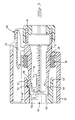
- Figure 1 shows a cross sectional view of an electrical connector 10 mating with a mating connector 100.
- the mating connector is represented at 100 however no details are shown of a mating connector.
- the mating connector 100 will have many other features, such as contact receiving passages and contacts, which are not shown in Figure 1.
- the electrical connector has a housing 12 with contact receiving passages 14 therein for receiving contacts, not shown.
- the electrical connector 10 has a mating end 16 and rearward end 18.
- the electrical connector 10 further has a shroud 20 which extends around the mating end 16 of the electrical connector 10 and also surrounds an inner body 28 of the electrical connector 10.
- Electrical connector 10 has a housing latch 22 having a latching protrusion 24 thereon.
- the housing latch 22 is used to latch and secure the mating connector 100 therewith.
- the mating connector 100 has a complimentary latching protrusion 110 which engages with the latching protrusion 24 to secure the mating connector 100 with the electrical connector 10.
- Electrical connector 10 has seal 26 which extends around the inner body 28 of the electrical connector 10 within the shroud 20. When the mating connector 100 is connected with the electrical connector 10 a portion of the mating connector 100 will engage the outer surfaces of seal 26 thereby providing a sealing interface between the electrical connector 10 and the mating connector 100.
- the mating connector 100 When the mating connector 100 is mated with the electrical connector 10, the mating connector is received within the shroud 20, and surrounds the inner body 28, and engages the seal 26 thereby providing the sealing interface.
- the mating connector 100 will have a series of electrical contacts secured therein to mate with the electrical contacts which are in the contact receiving passages 14, neither of these contacts being shown in Figure 1.
- the retention arms 30 each have a latching protrusion 32 which is used to engage a shoulder on the electrical contact to secure the contact therein.
- the contact retention arms 30 provide the outer wall of the electrical connector 10 and more specifically the outer wall of the inner body 28.
- a terminal position assurance member (TPA) 50 is inserted from the front end or the mating end 16 of the electrical connector 10 to provide a backup to the retention arms 30 to lock the contacts within the electrical connector 10 and also to alert the operator when a contact is improperly mounted within the electrical connector 10.
- the TPA 50 has an outer wall 52, a shoulder 54 and a locking surface 56 disposed therealong. When the TPA 50 is fully inserted onto the electrical connector 10, as is shown in Figure 1, the locking surface 56 will be received behind the contact retention arm 30 thereby preventing the deflection of the contact retention arm 32. In this state, the TPA is acting as a backup for the contact retention arm 30 in that it prevents the contact retention arm 30 from deflecting and thereby keeps the contact secured within the passage 14.
- FIG. 2 shows the electrical connector 10 and the TPA 50.
- the TPA 50 is shown in the prelatch position. That is, the position which it is in prior to and during the insertion of the contacts into the contact receiving passageway 14. In this position, the locking surface 56 is received forwardly from the contact retention arms 30, the shoulder 54 also received forwardly of the retention arms 30. This forms a space 58 behind the contact retention arm 30 which allows the contact retention arm 30 to be deflected into the space 58.
- the contacts can be inserted into the electrical connector 10 from the rear 18 of the electrical connector 10. During insertion of the contact, the contact retention arm 30 will deflect into the space 58.
- the contact retention arm 30 When the contact is properly seated within the contact passageway 14, the contact retention arm 30 will resile to its normal position and the latching protrusion 32 will latch behind a shoulder or some other space on the electrical contact, thereby securing the contact within the electrical connector 10.
- the TPA 50 When the TPA 50 is in the prelatch position, as shown in Figure 2, it will also act as an overstress for the retention arm 30.
- the outer wall 52' will prevent the contact retention arm 30 from being deflected to the point where it might break. The outer wall will serve this overstress function during insertion of the contacts and also if it is necessary for the contacts to be removed from the electrical connector 10 to either replace or repair the contacts.
- the TPA 50 can be moved from its prelatched position, as is shown in Figure 2, to its final position as is shown in Figure 1, because all of the contact retention arms 30 will be in their normal position. Therefore, the TPA 50 will provide a backup for all of the contact retention arms 30 thereby securing the contacts within the electrical connector 10.
- FIG 3 shows the electrical connector 10 having an electrical contact 70 improperly inserted within the electrical connector 10.
- the contact retention arm 30 is still deflected from its normal position. That is in Figure 2, the contact retention arm would be pushed up into space 58.
- the shoulder 54 will stub on the front end of the contact retention arm 30 thereby preventing the TPA 50 from being moved completely to a final position.
- the outer wall of the TPA and the outer wall of the inner body 28 of the electrical connector have been eliminated thereby having the contact retention arms 30 as the outer portion of the inner body 28 of the electrical connector.
- the TPA 50 only comprises one wall.
- the overall size of the connector is reduced because the two outer walls have been eliminated on the electrical connector and the TPA thereby reducing the overall size of the electrical connector.
Abstract
Description
- The present invention is directed to an electrical connector having a terminal position assurance device.
- It is known to provide a terminal position assurance device for electrical connectors. One form of terminal position assurance device is used in an electrical connector having deflectable latching arms. When the contacts are inserted into such a connector, the latching arms deflect to allow passage of the contacts. When the contacts are fully inserted, the latching arms resile into their initial position and latch behind a shoulder or some other surface on the contact thereby securing the contact within the connector. A terminal position assurance device is then inserted into the connector. The terminal position assurance device has surfaces that are received into a space proximate to the latching arms. When the terminal position assurance device is in place, the surfaces prevent the latching arms from deflecting and thereby secure the contacts within the connector. A further feature of the terminal position assurance device is that the terminal position assurance device cannot be inserted into the connector unless all of the latching arms are in their normal, non-deflected position. Therefore, if one of the contacts is not properly positioned, the latching arm will be deflected and the terminal position assurance device will be prevented from being inserted into the connector.
- A typical electrical connector having latching arms for securing the contacts within the passages has an outer wall surrounding the periphery of the electrical connector, on the outer side of the latching arms. Furthermore, the terminal position assurance device typically has two walls, one wall is a locking arm which is pushed into the electrical connector and received into the space to prevent the latching arm from deflecting and the second wall which is received on the outer side of the electrical connector wall to secure the terminal position assurance member onto the electrical connector. As the demand is for electrical connectors to become smaller and smaller, it is necessary to eliminate some of the plastic within the electrical connector in order to make the housing smaller.
- What is needed is an electrical connector having a smaller dimension than the typical electrical connector.
- The invention is directed to an electrical connector having a housing body with a contact receiving passage therein. The contact receiving passage has a contact retention arm for securing a contact within the passage. The contact retention arm forms the outer wall of the body. A terminal position assurance member has an outer wall with an inner shoulder and a locking surface. The outer wall is received around the contact retention arm. The terminal position assurance member has a first position in which the terminal position assurance member forms a space behind the contact retention arm. The terminal position assurance member has a second position wherein the locking surface is received behind the contact retention arm thereby preventing deflection of the contact retention arm.
- The invention is further directed to an electrical connector having a body with contact receiving passages therein. The contact receiving passage has a contact retention arm for securing a contact within the passage. The contact retention arm forms the outer wall of the body. A terminal position assurance member has a wall to be received on the outer side of the contact retention arm. The terminal position assurance member having a shoulder and a locking surface. The shoulder and the locking surface are formed on the inner side of the wall. The terminal position assurance member has a first position in which the terminal position assurance member forms a space behind the retention arm to allow deflection of the retention arm for insertion of the contact within the passage. The terminal position assurance member has a second position in which the locking surface is behind the retention arm thereby preventing the deflection of the retention arm and to secure the contact within the passage. When the contact is not properly seated within the passage and the retention arm is deflected, if the terminal position assurance member is moved from the first position to the second position, the shoulder will stub on the retention arm thereby indicating that the contact is improperly inserted within the passage.
- An embodiment of the present invention will now be described by way of example with reference to the accompanying drawings, in which:
- Figure 1 is a cross sectional view of an electrical connector with a terminal position assurance device in a locking position;
- Figure 2 is a cross section of an electrical connector showing the terminal position device in a pre-locking position; and
- Figure 3 is a cross sectional view of the electrical connector having an improperly mounted electrical contact within the electrical connector.
-
- Figure 1 shows a cross sectional view of an
electrical connector 10 mating with amating connector 100. The mating connector is represented at 100 however no details are shown of a mating connector. Themating connector 100 will have many other features, such as contact receiving passages and contacts, which are not shown in Figure 1. The electrical connector has ahousing 12 withcontact receiving passages 14 therein for receiving contacts, not shown. Theelectrical connector 10 has amating end 16 and rearwardend 18. Theelectrical connector 10 further has ashroud 20 which extends around themating end 16 of theelectrical connector 10 and also surrounds aninner body 28 of theelectrical connector 10. -
Electrical connector 10 has ahousing latch 22 having alatching protrusion 24 thereon. Thehousing latch 22 is used to latch and secure themating connector 100 therewith. Themating connector 100 has acomplimentary latching protrusion 110 which engages with thelatching protrusion 24 to secure themating connector 100 with theelectrical connector 10. -
Electrical connector 10 hasseal 26 which extends around theinner body 28 of theelectrical connector 10 within theshroud 20. When themating connector 100 is connected with the electrical connector 10 a portion of themating connector 100 will engage the outer surfaces ofseal 26 thereby providing a sealing interface between theelectrical connector 10 and themating connector 100. - When the
mating connector 100 is mated with theelectrical connector 10, the mating connector is received within theshroud 20, and surrounds theinner body 28, and engages theseal 26 thereby providing the sealing interface. Themating connector 100 will have a series of electrical contacts secured therein to mate with the electrical contacts which are in thecontact receiving passages 14, neither of these contacts being shown in Figure 1. - Within the
contact receiving passages 14 there arecontact retention arms 30. Theretention arms 30 each have alatching protrusion 32 which is used to engage a shoulder on the electrical contact to secure the contact therein. - In a typical electrical connector with a terminal position assurance device, there would be a space behind the latching arm, that is the side opposite to the
latching protrusion 32, and an outer peripheral wall received around the outer side of thecontact retention arms 30. However, in the present invention, thecontact retention arms 30 provide the outer wall of theelectrical connector 10 and more specifically the outer wall of theinner body 28. - A terminal position assurance member (TPA) 50 is inserted from the front end or the
mating end 16 of theelectrical connector 10 to provide a backup to theretention arms 30 to lock the contacts within theelectrical connector 10 and also to alert the operator when a contact is improperly mounted within theelectrical connector 10. The TPA 50 has anouter wall 52, ashoulder 54 and alocking surface 56 disposed therealong. When theTPA 50 is fully inserted onto theelectrical connector 10, as is shown in Figure 1, thelocking surface 56 will be received behind thecontact retention arm 30 thereby preventing the deflection of thecontact retention arm 32. In this state, the TPA is acting as a backup for thecontact retention arm 30 in that it prevents thecontact retention arm 30 from deflecting and thereby keeps the contact secured within thepassage 14. - Figure 2 shows the
electrical connector 10 and theTPA 50. TheTPA 50 is shown in the prelatch position. That is, the position which it is in prior to and during the insertion of the contacts into thecontact receiving passageway 14. In this position, thelocking surface 56 is received forwardly from thecontact retention arms 30, theshoulder 54 also received forwardly of theretention arms 30. This forms aspace 58 behind thecontact retention arm 30 which allows thecontact retention arm 30 to be deflected into thespace 58. When theTPA 50 is in this position, the contacts can be inserted into theelectrical connector 10 from the rear 18 of theelectrical connector 10. During insertion of the contact, thecontact retention arm 30 will deflect into thespace 58. When the contact is properly seated within thecontact passageway 14, thecontact retention arm 30 will resile to its normal position and thelatching protrusion 32 will latch behind a shoulder or some other space on the electrical contact, thereby securing the contact within theelectrical connector 10. When theTPA 50 is in the prelatch position, as shown in Figure 2, it will also act as an overstress for theretention arm 30. The outer wall 52' will prevent thecontact retention arm 30 from being deflected to the point where it might break. The outer wall will serve this overstress function during insertion of the contacts and also if it is necessary for the contacts to be removed from theelectrical connector 10 to either replace or repair the contacts. In order to remove the contacts, it is necessary for the operator to first move theTPA 50 to the prelatch position, then to deflect theretention arm 30 to remove the contact, and therefore, the outer wall 52' will serve to protect theretention arm 30 from overstress during this process. - If all of the contacts are properly inserted into the
electrical connector 10, theTPA 50 can be moved from its prelatched position, as is shown in Figure 2, to its final position as is shown in Figure 1, because all of thecontact retention arms 30 will be in their normal position. Therefore, theTPA 50 will provide a backup for all of thecontact retention arms 30 thereby securing the contacts within theelectrical connector 10. - Figure 3 shows the
electrical connector 10 having anelectrical contact 70 improperly inserted within theelectrical connector 10. In this position, it can be seen that thecontact retention arm 30 is still deflected from its normal position. That is in Figure 2, the contact retention arm would be pushed up intospace 58. When an attempt is made to move the TPA from the prelatch position as shown in Figure 2, into the final position as is shown in Figure 1, theshoulder 54 will stub on the front end of thecontact retention arm 30 thereby preventing theTPA 50 from being moved completely to a final position. This will alert the operator that one or more of thecontacts 70 are improperly positioned and that their position must be corrected before theTPA 50 can be moved to its final position so that theTPA 50 can act as a back up to thecontact retention arms 30 to prevent them from deflecting and allowing thecontact 30 from being removed from theelectrical connector 10. - In the present invention, the outer wall of the TPA and the outer wall of the
inner body 28 of the electrical connector have been eliminated thereby having thecontact retention arms 30 as the outer portion of theinner body 28 of the electrical connector. - Furthermore the
TPA 50 only comprises one wall. In the electrical connector of the present invention the overall size of the connector is reduced because the two outer walls have been eliminated on the electrical connector and the TPA thereby reducing the overall size of the electrical connector. - The electrical connector of the present invention and many of its attendant advantages will be understood from the foregoing description. It is apparent that various changes may be made in the form, construction, and arrangement of parts thereof without departing from the scope of the invention.
Claims (8)
- An electrical connector (10) comprising:
a housing body (12) having at least one contact receiving passageway (14) having at least one contact retention member (30) aligned with each contact receiving passageway (14);
characterized by a terminal position assurance member (50) movable between a prelatch position and a latch position, the terminal position assurance member (50) having a prelatch surface (52) and a locking surface (56), such that when the terminal position assurance member (50) is in the prelatch position, the prelatch surface (52) is located adjacent the contact retention member (30) but distanced from the contact retention member (30) by a recess (58) so as to accommodate deflection thereof, and when the terminal position assurance member (50) is in the latch position, the locking surface (56) is located adjacent to and in contact with the contact retention member (30) thereby preventing deflection thereof. - The electrical connector (10) of claim 1,
characterized in that the locking surface (56) and the prelatch surface (52) define a shoulder therebetween, such that the shoulder (54) stubs on the contact retention member (30)when the contact retention member (30)is deflected into the recess (58), thereby precluding the terminal position assurance member (50) from moving from the prelatch position to the latch position. - The electrical connector (10) of claim 1 or 2 characterized in that the prelatch surface (52) is adjacent the locking surface (56), the prelatch surface (52) being offset from the locking surface(56).
- The electrical connector (10) of claim 1,2 or 3 characterized in that the contact retention member (30) has a projection (32) extending into the contact receiving passageway (14) for engaging the contacts (70), such that when the contact (70) is improperly received within the contact receiving passageway (14), the projection (32) is engaged by the contact (70), thereby deflecting the contact retention member (30) into the recess (58), and when the contact (70) is properly received in the contact receiving passageway (14), the projection (32) engages and retains the contact (70) within the contact receiving passageway (14).
- The electrical connector (10) of any preceding claim characterized in that the housing body (12) has a shroud (20) extending therearound.
- The electrical connector (10) of claim 5, characterized in that the shroud (20) is integrally formed with the housing body (12).
- The electrical connector (10) of claim 5 or 6 characterized in that the shroud (20) has a mating projection (24) extending inwardly toward the housing body (12) for engaging a complementary projection (110) of a mating connector (100) such that when the electrical connector (10) is mated with a complementary connector (100), the mating projection (24) engages the complementary projection (110) to retain the connectors (10,100) in mating engagement.
- The electrical connector (10) of any preceding claim characterized in that the housing body (12) has a seal (26) annularly disposed about the housing body (12).
Applications Claiming Priority (2)
| Application Number | Priority Date | Filing Date | Title |
|---|---|---|---|
| US5135297P | 1997-06-30 | 1997-06-30 | |
| US51352P | 1997-06-30 |
Publications (3)
| Publication Number | Publication Date |
|---|---|
| EP0895312A2 true EP0895312A2 (en) | 1999-02-03 |
| EP0895312A3 EP0895312A3 (en) | 1999-12-22 |
| EP0895312B1 EP0895312B1 (en) | 2007-12-12 |
Family
ID=21970779
Family Applications (1)
| Application Number | Title | Priority Date | Filing Date |
|---|---|---|---|
| EP98305002A Expired - Lifetime EP0895312B1 (en) | 1997-06-30 | 1998-06-25 | An electrical connector having a terminal position assurance device |
Country Status (5)
| Country | Link |
|---|---|
| US (1) | US6045404A (en) |
| EP (1) | EP0895312B1 (en) |
| JP (1) | JP4471318B2 (en) |
| DE (1) | DE69838831T2 (en) |
| ES (1) | ES2297875T3 (en) |
Cited By (8)
| Publication number | Priority date | Publication date | Assignee | Title |
|---|---|---|---|---|
| FR2788890A1 (en) * | 1999-01-22 | 2000-07-28 | Whitaker Corp | Electrical connector for motor use includes elastic locking components on both halves, increasing displacement and providing secure inter-locking |
| DE19912202A1 (en) * | 1999-03-18 | 2000-10-19 | Framatome Connectors Int | Electrical plug connector with detachable electrical contacts has hooks for locking inserted electrical contacts |
| EP1073155A2 (en) * | 1999-07-21 | 2001-01-31 | The Whitaker Corporation | Connector with primary and secondary terminal retention features |
| EP1211757A1 (en) * | 2000-11-30 | 2002-06-05 | Sumitomo Wiring Systems, Ltd. | Elektrical connector |
| US6554645B1 (en) | 1999-07-21 | 2003-04-29 | Amp Deutschland Gmbh | Primary terminal retention feature for connectors |
| EP1562263A1 (en) * | 2004-01-28 | 2005-08-10 | Delphi Technologies, Inc. | Electrical connector |
| EP2164135A1 (en) * | 2008-09-12 | 2010-03-17 | Tyco Electronics Corporation | Blade and receptacle power connector |
| CN111193138A (en) * | 2018-11-14 | 2020-05-22 | 住友电装株式会社 | Connector with a locking member |
Families Citing this family (29)
| Publication number | Priority date | Publication date | Assignee | Title |
|---|---|---|---|---|
| US6126484A (en) * | 1999-11-01 | 2000-10-03 | The Whitaker Corporation | Electrical connector with molded latch stop |
| US20020031947A1 (en) * | 2000-07-17 | 2002-03-14 | Gundermann James Edward | Electrical connector module and electrical connector assembly including same |
| JP3778023B2 (en) * | 2001-07-23 | 2006-05-24 | 住友電装株式会社 | Waterproof connector |
| US6599150B1 (en) * | 2002-03-22 | 2003-07-29 | Tyco Electronics Corporation | Electrical connector assembly |
| US6705886B1 (en) * | 2003-01-23 | 2004-03-16 | Fci Americas Technology, Inc. | Electrical connector having connector position assurance member |
| CA2454438A1 (en) * | 2003-02-07 | 2004-08-07 | Hypertronics Corporation | Connecting device |
| US6811424B2 (en) | 2003-03-26 | 2004-11-02 | Fci Americas Technology, Inc. | Electrical connector having connector position assurance member |
| US6921279B2 (en) * | 2003-06-05 | 2005-07-26 | Fci Americas Technology, Inc. | Electrical connector with connector position assurance member |
| US6857892B2 (en) | 2003-06-05 | 2005-02-22 | Fci Americas Technology, Inc. | Electrical connector with connector position assurance member |
| US6964579B2 (en) * | 2003-06-06 | 2005-11-15 | Fci Americas Technology, Inc. | Position assured connector |
| DE10332892B4 (en) * | 2003-07-19 | 2011-01-27 | Leopold Kostal Gmbh & Co. Kg | Chamber housing for forming an electrical connector part |
| EP1557908B1 (en) * | 2004-01-05 | 2007-08-15 | Sumitomo Wiring Systems, Ltd. | A connector |
| US7044806B2 (en) * | 2004-04-09 | 2006-05-16 | Fci America Technology, Inc. | Electrical connector terminal position assurance polarization |
| FR2875957A1 (en) * | 2004-09-29 | 2006-03-31 | Fci Sa | DEVICE FOR LATCHING CONNECTOR ELEMENTS AND CONNECTOR COMPRISING SAME |
| US7387545B2 (en) | 2006-03-24 | 2008-06-17 | Fci Americas Technology, Inc. | Electrical connector with pre-locked terminal position assurance (TPA) |
| US20080254666A1 (en) * | 2006-10-10 | 2008-10-16 | Gavril Cret | Electrical connector and associated methods |
| JP4922424B2 (en) * | 2010-03-05 | 2012-04-25 | 日本航空電子工業株式会社 | Waterproof connector |
| US8651901B2 (en) * | 2011-05-04 | 2014-02-18 | Tyco Electronics Corporation | Electrical connector having terminal position assurance |
| JP5809083B2 (en) * | 2012-03-01 | 2015-11-10 | タイコエレクトロニクスジャパン合同会社 | Waterproof connector |
| WO2013135849A1 (en) * | 2012-03-16 | 2013-09-19 | Delphi Connection Systems Holding France | Electrical connector |
| USD787448S1 (en) | 2014-08-18 | 2017-05-23 | Interlemo Holding S.A. | Electrical connector |
| USD863221S1 (en) | 2015-09-04 | 2019-10-15 | Interlemo Holding Sa | Illuminable female connector |
| US9935389B1 (en) * | 2017-02-23 | 2018-04-03 | Sumitomo Wiring Systems, Ltd. | Inline connector housing assemblies with removable TPA |
| US10355393B2 (en) | 2017-11-06 | 2019-07-16 | Te Connectivity Corporation | Sealed rear-loaded electrical connector housings, assemblies, and systems |
| US10389061B2 (en) | 2017-11-17 | 2019-08-20 | Te Connectivity Corporation | Electrical connector having a rear seal and a rear-loaded cover/retainer member |
| JP6575586B2 (en) * | 2017-12-21 | 2019-09-18 | 株式会社オートネットワーク技術研究所 | Shield terminal |
| US10177498B1 (en) | 2018-02-19 | 2019-01-08 | Te Connectivity Corporation | Stacking electrical connector |
| KR20200088769A (en) * | 2019-01-15 | 2020-07-23 | 타이코에이엠피 주식회사 | Connector assembly and home appliances having the connector assembly |
| EP3886264B1 (en) * | 2020-03-27 | 2023-11-08 | Aptiv Technologies Limited | Sealed electrical connector |
Citations (6)
| Publication number | Priority date | Publication date | Assignee | Title |
|---|---|---|---|---|
| US5071369A (en) * | 1990-12-05 | 1991-12-10 | Amp Incorporated | Electrical connector having a terminal position assurance member |
| US5083933A (en) * | 1990-09-28 | 1992-01-28 | Molex Incorporated | Electrical connector with fully shrouded lock |
| EP0657969A1 (en) * | 1993-12-06 | 1995-06-14 | Sumitomo Wiring Systems, Ltd. | Connector assembly |
| WO1996013079A1 (en) * | 1994-10-25 | 1996-05-02 | The Whitaker Corporation | Sealable connector assembly having secondary lock |
| EP0716473A1 (en) * | 1994-12-08 | 1996-06-12 | Molex Incorporated | Connector with a front end mounted terminal position assurance system |
| JPH08306431A (en) * | 1995-05-02 | 1996-11-22 | Yazaki Corp | Connector having terminal locking tool |
Family Cites Families (12)
| Publication number | Priority date | Publication date | Assignee | Title |
|---|---|---|---|---|
| US4891021A (en) * | 1986-06-12 | 1990-01-02 | Amp Incorporated | High density socket contact receptacle |
| JPH0528689Y2 (en) * | 1988-08-26 | 1993-07-23 | ||
| US4973268A (en) * | 1989-10-10 | 1990-11-27 | Amp Incorporated | Multi-contact electrical connector with secondary lock |
| US5281168A (en) * | 1992-11-20 | 1994-01-25 | Molex Incorporated | Electrical connector with terminal position assurance system |
| JPH0660072U (en) * | 1993-01-27 | 1994-08-19 | 住友電装株式会社 | Waterproof connector |
| JP2813622B2 (en) * | 1993-08-06 | 1998-10-22 | 矢崎総業株式会社 | Connector having a front member for fixing terminals |
| US5522740A (en) * | 1994-09-29 | 1996-06-04 | Molex Incorporated | Electrical connector with terminal position assurance device that facilitates fully inserting a terminal |
| US5575692A (en) * | 1994-12-08 | 1996-11-19 | Molex Incorporated | Electrical connector with a rear end mounted terminal position assurance device |
| GB9608746D0 (en) * | 1996-04-26 | 1996-07-03 | Amp Great Britain | Connector with terminal position assurance member |
| JPH09330757A (en) * | 1996-06-10 | 1997-12-22 | Yazaki Corp | Connector |
| JP3646836B2 (en) * | 1997-03-27 | 2005-05-11 | 住友電装株式会社 | connector |
| JP3612926B2 (en) * | 1997-03-27 | 2005-01-26 | 住友電装株式会社 | connector |
-
1998
- 1998-06-11 US US09/095,634 patent/US6045404A/en not_active Expired - Lifetime
- 1998-06-24 JP JP17722698A patent/JP4471318B2/en not_active Expired - Fee Related
- 1998-06-25 EP EP98305002A patent/EP0895312B1/en not_active Expired - Lifetime
- 1998-06-25 DE DE69838831T patent/DE69838831T2/en not_active Expired - Lifetime
- 1998-06-25 ES ES98305002T patent/ES2297875T3/en not_active Expired - Lifetime
Patent Citations (6)
| Publication number | Priority date | Publication date | Assignee | Title |
|---|---|---|---|---|
| US5083933A (en) * | 1990-09-28 | 1992-01-28 | Molex Incorporated | Electrical connector with fully shrouded lock |
| US5071369A (en) * | 1990-12-05 | 1991-12-10 | Amp Incorporated | Electrical connector having a terminal position assurance member |
| EP0657969A1 (en) * | 1993-12-06 | 1995-06-14 | Sumitomo Wiring Systems, Ltd. | Connector assembly |
| WO1996013079A1 (en) * | 1994-10-25 | 1996-05-02 | The Whitaker Corporation | Sealable connector assembly having secondary lock |
| EP0716473A1 (en) * | 1994-12-08 | 1996-06-12 | Molex Incorporated | Connector with a front end mounted terminal position assurance system |
| JPH08306431A (en) * | 1995-05-02 | 1996-11-22 | Yazaki Corp | Connector having terminal locking tool |
Non-Patent Citations (1)
| Title |
|---|
| PATENT ABSTRACTS OF JAPAN vol. 1997, no. 03, 31 March 1997 (1997-03-31) & JP 08 306431 A (YAZAKI CORP), 22 November 1996 (1996-11-22) * |
Cited By (13)
| Publication number | Priority date | Publication date | Assignee | Title |
|---|---|---|---|---|
| FR2788890A1 (en) * | 1999-01-22 | 2000-07-28 | Whitaker Corp | Electrical connector for motor use includes elastic locking components on both halves, increasing displacement and providing secure inter-locking |
| DE19912202A1 (en) * | 1999-03-18 | 2000-10-19 | Framatome Connectors Int | Electrical plug connector with detachable electrical contacts has hooks for locking inserted electrical contacts |
| DE19912202B4 (en) * | 1999-03-18 | 2004-05-19 | Framatome Connectors Daut + Rietz Gmbh | Electrical connector with detachable electrical contacts |
| EP1073155A2 (en) * | 1999-07-21 | 2001-01-31 | The Whitaker Corporation | Connector with primary and secondary terminal retention features |
| EP1073155A3 (en) * | 1999-07-21 | 2002-04-24 | The Whitaker Corporation | Connector with primary and secondary terminal retention features |
| US6554645B1 (en) | 1999-07-21 | 2003-04-29 | Amp Deutschland Gmbh | Primary terminal retention feature for connectors |
| US6638108B2 (en) | 2000-11-30 | 2003-10-28 | Sumitomo Wiring Systems, Ltd. | Connector with plural housings accommodated in a casing |
| EP1211757A1 (en) * | 2000-11-30 | 2002-06-05 | Sumitomo Wiring Systems, Ltd. | Elektrical connector |
| EP1562263A1 (en) * | 2004-01-28 | 2005-08-10 | Delphi Technologies, Inc. | Electrical connector |
| US7021952B2 (en) | 2004-01-28 | 2006-04-04 | Delphi Technologies, Inc. | Electrical plug connector |
| EP2164135A1 (en) * | 2008-09-12 | 2010-03-17 | Tyco Electronics Corporation | Blade and receptacle power connector |
| US7731520B1 (en) | 2008-09-12 | 2010-06-08 | Tyco Electronics Corporation | Blade and receptacle power connector |
| CN111193138A (en) * | 2018-11-14 | 2020-05-22 | 住友电装株式会社 | Connector with a locking member |
Also Published As
| Publication number | Publication date |
|---|---|
| JP4471318B2 (en) | 2010-06-02 |
| ES2297875T3 (en) | 2008-05-01 |
| JPH1167320A (en) | 1999-03-09 |
| US6045404A (en) | 2000-04-04 |
| DE69838831D1 (en) | 2008-01-24 |
| EP0895312A3 (en) | 1999-12-22 |
| DE69838831T2 (en) | 2008-12-04 |
| EP0895312B1 (en) | 2007-12-12 |
Similar Documents
| Publication | Publication Date | Title |
|---|---|---|
| US6045404A (en) | Electrical connector having a terminal position assurance device | |
| US5695368A (en) | Electrical terminal with protected locking lance and a connector therefor | |
| EP0804821B1 (en) | Housing latch with connector position assurance device | |
| EP0599165B1 (en) | Electrical connector with terminal position assurance system | |
| EP0716473B1 (en) | Connector with a front end mounted terminal position assurance system | |
| EP0716475B1 (en) | Electrical connector with a rear end mounted terminal position assurance device | |
| US6244880B1 (en) | Low-insertion force connector | |
| US6244900B1 (en) | Electrical connector with redundant prevention of excessive forward movement of a terminal fitting in a cavity of a connector housing | |
| US7722381B2 (en) | Connector | |
| US20100055961A1 (en) | Terminal position assurance member for electrical connector | |
| WO1996032760A1 (en) | Electrical connector with secondary lock | |
| EP0903814B1 (en) | Connector provided with a retainer | |
| EP0125786A2 (en) | Electrical connector assembly | |
| US5593326A (en) | Electrical connector with secondary latch | |
| EP0902504B1 (en) | Front holder-incorporating connector | |
| US6247966B1 (en) | Electrical connector with exposed molded latches | |
| US4932899A (en) | Electrical connector | |
| US6116953A (en) | Electrical connector having a terminal position assurance device | |
| WO2011069610A1 (en) | Connector assembly | |
| US6126484A (en) | Electrical connector with molded latch stop | |
| EP0975061B1 (en) | A watertight connector with inertial locking mechanism | |
| US6004164A (en) | Connector provided with a retainer | |
| US20040171294A1 (en) | Connector | |
| EP0723313B1 (en) | Electrical connector | |
| EP1012916B1 (en) | Connector with terminal position assurance member |
Legal Events
| Date | Code | Title | Description |
|---|---|---|---|
| PUAI | Public reference made under article 153(3) epc to a published international application that has entered the european phase |
Free format text: ORIGINAL CODE: 0009012 |
|
| AK | Designated contracting states |
Kind code of ref document: A2 Designated state(s): DE ES FR GB IT |
|
| AX | Request for extension of the european patent |
Free format text: AL;LT;LV;MK;RO;SI |
|
| PUAL | Search report despatched |
Free format text: ORIGINAL CODE: 0009013 |
|
| AK | Designated contracting states |
Kind code of ref document: A3 Designated state(s): AT BE CH CY DE DK ES FI FR GB GR IE IT LI LU MC NL PT SE |
|
| AX | Request for extension of the european patent |
Free format text: AL;LT;LV;MK;RO;SI |
|
| RIC1 | Information provided on ipc code assigned before grant |
Free format text: 6H 01R 13/436 A, 6H 01R 13/422 B, 6H 01R 13/627 B, 6H 01R 13/52 B |
|
| 17P | Request for examination filed |
Effective date: 20000620 |
|
| AKX | Designation fees paid |
Free format text: DE ES FR GB IT |
|
| GRAP | Despatch of communication of intention to grant a patent |
Free format text: ORIGINAL CODE: EPIDOSNIGR1 |
|
| GRAS | Grant fee paid |
Free format text: ORIGINAL CODE: EPIDOSNIGR3 |
|
| GRAA | (expected) grant |
Free format text: ORIGINAL CODE: 0009210 |
|
| AK | Designated contracting states |
Kind code of ref document: B1 Designated state(s): DE ES FR GB IT |
|
| REG | Reference to a national code |
Ref country code: GB Ref legal event code: FG4D |
|
| REF | Corresponds to: |
Ref document number: 69838831 Country of ref document: DE Date of ref document: 20080124 Kind code of ref document: P |
|
| REG | Reference to a national code |
Ref country code: ES Ref legal event code: FG2A Ref document number: 2297875 Country of ref document: ES Kind code of ref document: T3 |
|
| ET | Fr: translation filed | ||
| PLBE | No opposition filed within time limit |
Free format text: ORIGINAL CODE: 0009261 |
|
| STAA | Information on the status of an ep patent application or granted ep patent |
Free format text: STATUS: NO OPPOSITION FILED WITHIN TIME LIMIT |
|
| 26N | No opposition filed |
Effective date: 20080915 |
|
| PGFP | Annual fee paid to national office [announced via postgrant information from national office to epo] |
Ref country code: DE Payment date: 20120627 Year of fee payment: 15 |
|
| PGFP | Annual fee paid to national office [announced via postgrant information from national office to epo] |
Ref country code: GB Payment date: 20120625 Year of fee payment: 15 Ref country code: FR Payment date: 20120705 Year of fee payment: 15 |
|
| PGFP | Annual fee paid to national office [announced via postgrant information from national office to epo] |
Ref country code: IT Payment date: 20120625 Year of fee payment: 15 |
|
| PGFP | Annual fee paid to national office [announced via postgrant information from national office to epo] |
Ref country code: ES Payment date: 20120626 Year of fee payment: 15 |
|
| GBPC | Gb: european patent ceased through non-payment of renewal fee |
Effective date: 20130625 |
|
| REG | Reference to a national code |
Ref country code: DE Ref legal event code: R119 Ref document number: 69838831 Country of ref document: DE Effective date: 20140101 |
|
| REG | Reference to a national code |
Ref country code: FR Ref legal event code: ST Effective date: 20140228 |
|
| PG25 | Lapsed in a contracting state [announced via postgrant information from national office to epo] |
Ref country code: GB Free format text: LAPSE BECAUSE OF NON-PAYMENT OF DUE FEES Effective date: 20130625 Ref country code: DE Free format text: LAPSE BECAUSE OF NON-PAYMENT OF DUE FEES Effective date: 20140101 |
|
| PG25 | Lapsed in a contracting state [announced via postgrant information from national office to epo] |
Ref country code: FR Free format text: LAPSE BECAUSE OF NON-PAYMENT OF DUE FEES Effective date: 20130701 Ref country code: IT Free format text: LAPSE BECAUSE OF NON-PAYMENT OF DUE FEES Effective date: 20130625 |
|
| REG | Reference to a national code |
Ref country code: ES Ref legal event code: FD2A Effective date: 20140708 |
|
| PG25 | Lapsed in a contracting state [announced via postgrant information from national office to epo] |
Ref country code: ES Free format text: LAPSE BECAUSE OF NON-PAYMENT OF DUE FEES Effective date: 20130626 |