EP0894709B1 - Fire resistant pressure relief panel assembly - Google Patents
Fire resistant pressure relief panel assembly Download PDFInfo
- Publication number
- EP0894709B1 EP0894709B1 EP98202609A EP98202609A EP0894709B1 EP 0894709 B1 EP0894709 B1 EP 0894709B1 EP 98202609 A EP98202609 A EP 98202609A EP 98202609 A EP98202609 A EP 98202609A EP 0894709 B1 EP0894709 B1 EP 0894709B1
- Authority
- EP
- European Patent Office
- Prior art keywords
- retaining ring
- support pan
- panel assembly
- pressure relief
- decompression
- Prior art date
- Legal status (The legal status is an assumption and is not a legal conclusion. Google has not performed a legal analysis and makes no representation as to the accuracy of the status listed.)
- Expired - Lifetime
Links
- 230000009970 fire resistant effect Effects 0.000 title claims description 14
- 230000006837 decompression Effects 0.000 claims description 57
- 238000000926 separation method Methods 0.000 claims description 18
- 230000002093 peripheral effect Effects 0.000 claims description 10
- 229910052782 aluminium Inorganic materials 0.000 claims description 5
- XAGFODPZIPBFFR-UHFFFAOYSA-N aluminium Chemical compound [Al] XAGFODPZIPBFFR-UHFFFAOYSA-N 0.000 claims description 5
- 239000011152 fibreglass Substances 0.000 claims description 4
- 229910018487 Ni—Cr Inorganic materials 0.000 claims description 3
- VNNRSPGTAMTISX-UHFFFAOYSA-N chromium nickel Chemical compound [Cr].[Ni] VNNRSPGTAMTISX-UHFFFAOYSA-N 0.000 claims description 3
- 229910001220 stainless steel Inorganic materials 0.000 claims description 3
- 239000010935 stainless steel Substances 0.000 claims description 3
- 230000001419 dependent effect Effects 0.000 claims 5
- 244000309464 bull Species 0.000 description 12
- 229910000831 Steel Inorganic materials 0.000 description 7
- 239000000463 material Substances 0.000 description 7
- 239000010959 steel Substances 0.000 description 7
- 229910052793 cadmium Inorganic materials 0.000 description 6
- BDOSMKKIYDKNTQ-UHFFFAOYSA-N cadmium atom Chemical compound [Cd] BDOSMKKIYDKNTQ-UHFFFAOYSA-N 0.000 description 6
- RTAQQCXQSZGOHL-UHFFFAOYSA-N Titanium Chemical compound [Ti] RTAQQCXQSZGOHL-UHFFFAOYSA-N 0.000 description 4
- QVGXLLKOCUKJST-UHFFFAOYSA-N atomic oxygen Chemical compound [O] QVGXLLKOCUKJST-UHFFFAOYSA-N 0.000 description 4
- 229910052760 oxygen Inorganic materials 0.000 description 4
- 239000001301 oxygen Substances 0.000 description 4
- 239000000779 smoke Substances 0.000 description 4
- 229910052719 titanium Inorganic materials 0.000 description 4
- 239000010936 titanium Substances 0.000 description 4
- 230000004044 response Effects 0.000 description 3
- 230000000712 assembly Effects 0.000 description 2
- 238000000429 assembly Methods 0.000 description 2
- 230000004888 barrier function Effects 0.000 description 2
- 238000005266 casting Methods 0.000 description 2
- 229910017052 cobalt Inorganic materials 0.000 description 2
- 239000010941 cobalt Substances 0.000 description 2
- GUTLYIVDDKVIGB-UHFFFAOYSA-N cobalt atom Chemical compound [Co] GUTLYIVDDKVIGB-UHFFFAOYSA-N 0.000 description 2
- 238000003754 machining Methods 0.000 description 2
- 229910052751 metal Inorganic materials 0.000 description 2
- 239000002184 metal Substances 0.000 description 2
- 206010003497 Asphyxia Diseases 0.000 description 1
- 229920002323 Silicone foam Polymers 0.000 description 1
- 230000003466 anti-cipated effect Effects 0.000 description 1
- 230000015556 catabolic process Effects 0.000 description 1
- 230000008859 change Effects 0.000 description 1
- 238000006243 chemical reaction Methods 0.000 description 1
- 230000006835 compression Effects 0.000 description 1
- 238000007906 compression Methods 0.000 description 1
- 238000010276 construction Methods 0.000 description 1
- 238000006731 degradation reaction Methods 0.000 description 1
- 230000000694 effects Effects 0.000 description 1
- 229920001971 elastomer Polymers 0.000 description 1
- 229940014425 exodus Drugs 0.000 description 1
- 230000000977 initiatory effect Effects 0.000 description 1
- 230000003601 intercostal effect Effects 0.000 description 1
- 238000012423 maintenance Methods 0.000 description 1
- 230000013011 mating Effects 0.000 description 1
- 230000008018 melting Effects 0.000 description 1
- 238000002844 melting Methods 0.000 description 1
- 238000005192 partition Methods 0.000 description 1
- 238000005498 polishing Methods 0.000 description 1
- 229920001296 polysiloxane Polymers 0.000 description 1
- 239000013514 silicone foam Substances 0.000 description 1
- 230000007480 spreading Effects 0.000 description 1
Images



Classifications
-
- B—PERFORMING OPERATIONS; TRANSPORTING
- B64—AIRCRAFT; AVIATION; COSMONAUTICS
- B64C—AEROPLANES; HELICOPTERS
- B64C1/00—Fuselages; Constructional features common to fuselages, wings, stabilising surfaces or the like
- B64C1/18—Floors
-
- B—PERFORMING OPERATIONS; TRANSPORTING
- B64—AIRCRAFT; AVIATION; COSMONAUTICS
- B64C—AEROPLANES; HELICOPTERS
- B64C1/00—Fuselages; Constructional features common to fuselages, wings, stabilising surfaces or the like
- B64C1/06—Frames; Stringers; Longerons ; Fuselage sections
- B64C1/10—Bulkheads
-
- B—PERFORMING OPERATIONS; TRANSPORTING
- B64—AIRCRAFT; AVIATION; COSMONAUTICS
- B64C—AEROPLANES; HELICOPTERS
- B64C1/00—Fuselages; Constructional features common to fuselages, wings, stabilising surfaces or the like
- B64C2001/009—Fuselages; Constructional features common to fuselages, wings, stabilising surfaces or the like comprising decompression panels or valves for pressure equalisation in fuselages or floors
Definitions
- the present invention relates to decompression panels for use in a separation structure, such as a bulkhead or wall, and more particularly, to decompression panels having a pressure relief panel that releases entirely from the device during rapid decompression of an aircraft compartment.
- An aircraft is typically subdivided into two or more compartments separated by structures, e.g., walls, bulkheads, floors, etc. During flight, these compartments are positively pressurized relative to the atmospheric pressure outside the aircraft. If an opening is created between one compartment and the exterior atmosphere, the pressure difference causes a sudden exodus of interior aircraft air. As air is rushing out the opening, an almost immediate propagation of the pressure difference causes the other compartments to also attempt to decompress.
- decompression panels between compartments to quickly equalize the pressure differential.
- a difference in pressure between compartments that is not relieved rapidly could lead to deformation of a separation structure and/or surrounding components.
- Known decompression panels have a sandwich type construction in which a pressure relief panel is released to fully reveal an opening through the separation structure. This allows air to quickly pass therethrough and quickly relieve the pressure difference.
- These types of decompression panels are sometimes referred to as full release blowout panels. US-A-4 899 960 shows such a panel assembly.
- the present invention provides a fire-resistant decompression panel assembly for use at a separation structure to quickly relieve pressure differences between two adjacent aircraft compartments.
- a decompression panel assembly formed in accordance with the present invention is defined in the independent claims 1,5 and 16.
- the assembly includes a support pan having a first surface, an opening, and a raised portion (e.g., a bull nose) surrounding the periphery of the opening and extending normally outward from the first surface.
- a pressure relief panel is used to cover the support pan opening and is therefore sized slightly larger than the opening.
- a retaining ring connects to the support pan such that the outer edge of the pressure relief panel is located and held between the raised portion and the retaining ring.
- the retaining ring includes a number of segments or fingers available to flex independently of one another.
- the retaining ring is a single rectangular member having fingers formed from a number of spaced-apart slits extending into the retaining ring along the ring's inner periphery. Stress relief holes are provided at the ends of the slits to prevent crack growth initiation.
- the fire resistant pressure relief panel is clamped between the retaining ring and the raised portion.
- the contacts between the ring, the pressure relief panel, and the raised portion are substantially airtight contacts, so that the panel assembly can prohibit the flow of oxygen and smoke between compartments and thereby resist the spread of fire and smoke.
- one or more of the retaining ring fingers flexes slightly outward and in so doing reduces the holding force applied to the fire resistant pressure relief panel. This allows the pressure difference between compartments to easily and quickly detach the entire panel from the assembly.
- the pressure relief panel is made of a fire resistant fiberglass and the retaining ring is fabricated from nickel chromium stainless steel.
- the panel assembly is preferably oriented in an upright plane with the support pan opening, pressure relief panel, and retaining ring rectangularly shaped and oriented with their longitudinal axes extending laterally.
- a number of index pins interconnect between the support pan and the retaining ring.
- the index pins extend from the support pan first surface and protrude through clearance holes provided in the retaining ring.
- the index pins are located such that the pressure relief panel edges just contact the pins.
- the pins therefore act as stop guides.
- the support pan may further include a recess surrounding the raised portion.
- An inner seal is sized and located within the recess, and is pocketed between the support pan and the retaining ring during use. The inner seal acts as an ablatant heat sink.
- the panel assembly may also include a grill for use in protecting the fire resistant pressure relief panel from objects within the compartment.
- the support pan includes a second surface having a peripheral flange extending normally therefrom about the pan opening.
- a number of secondary pressure relief holes extend through both the grill sides and the flange to provide relief pressure equalization should the face of the grill be blocked.
- the grill is attached to the flange and generally covers the entire support pan opening.
- the grill is preferably formed by machining or casting a heat tolerant material, such as aluminum, titanium, cobalt, steel, etc.
- FIGURE 1 is a perspective view of one embodiment of a decompression panel assembly 12 formed in accordance with the present invention.
- the assembly is shown installed in a bulkhead (i.e., more generally, a separation structure 14) that divides a cargo bay and an electronics bay.
- the view of FIGURE 1 is taken from the cargo bay, looking forward. This particular separation structure and inter-compartment location was selected for illustrative purposes only.
- the assembly may be secured through other separation structures in an aircraft or space vehicle at locations in which sudden decompression may be required between adjacent compartments.
- the decompression panel assembly 12 generally includes a retaining ring 22, a fire resistant pressure relief panel 24, and a support pan 26 having an opening 28.
- the pressure relief panel 24 covers the support pan opening 28 and is held in place by the retaining ring 22.
- the pressure relief panel effectively forms a substantially airtight seal around the opening 28 to resist the passage of flame or smoke from one adjacent compartment to the next.
- the retaining ring 22 flexes slightly to allow the pressure relief panel 24 to quickly and fully release from the assembly 12 and reveal the support pan opening 28, thereby allowing pressure to quickly equalize between adjacent compartments.
- the panel assembly 12 optionally includes a grill 30 to prohibit the pressure relief panel from being unintentionally dislodged (as might easily happen from luggage or personnel moving about in the cargo bay.)
- the support pan 26 is a rectangularly shaped planar member having a first surface 36 and a second surface 34 (see FIGURE 3.) As shown in FIGURE 3, the opening 28 is generally positioned in the center of the pan. It is preferable to also use a rectangular or square opening, and, if possible, to orient the assembly 12 in the separation structure, so that the plane of the assembly is upright and the assembly's longitudinal axis is lateral as illustrated in FIGURE 1. This orientation helps to further reduce the spread of fire between compartments by providing the least amount of vertical distance available for a flame to propagate.
- the support pan 26 is preferably formed by machining or casting a heat tolerant material, e.g., aluminum, titanium, cobalt, steel, etc. If aluminum is selected, it should be increased in gauge thickness to counteract any metal degradation effects during a fire. An average support pan thickness of about 0,38cm (0.15 inches) to about 0,51cm (0.20 inches) has been shown to work well.
- the decompression panel assembly 12 is a one-way decompression relief panel, i.e., the pressure relief panel 24 is intended to fully release in one direction.
- the support pan second surface 34 (shown best in FIGURE 2) is the side that faces the high pressure compartment 39.
- the support pan first surface 36 (shown best in FIGURE 3) is the side that faces the low pressure compartment 41.
- the support pan 26 is installed in the separation structure 14 using a number of fasteners 42.
- the fasteners 42 are inserted through the support pan and edge seals 46, through holes in the separation structure 14, and into the capped receptacles common to the separation structure on the low pressure compartment side.
- the edge seals 46 keep the pressure relief assembly in substantially airtight contact with the separation structure.
- the seals 46 are preferably made of a heat resistant, nonflammable material, such as silicone.
- support pan fasteners 42 are connected to portions of the separation structure 14 that are themselves strong enough to maintain their shape and position during a rapid decompression event.
- Exemplary structures include support stanchions, contour rails, intercostals, floor beams, etc.
- Preferred fasteners 42 include cadmium steel quarter-turn stud assemblies having a pin, snap ring, and mating grommet. These types of fasteners are preferred because they allow quick and easy removal of the decompression panel assembly should the need arise, e.g., for maintenance or compartment access.
- the decompression panel assembly 12 for this application further includes capped receptacles 48 positioned near the support pan's 26 upper and lower side edges.
- the capped receptacles attach adjacent panel partitions 50 (see FIGURE 1) above and below the decompression panel assembly.
- the support pan second surface 34 includes a peripheral flange 54 extending normally outward therefrom for use in connecting the grill 30 to the support pan 26.
- the peripheral flange 54 is made of a heat tolerant nonflammable material integrally formed with the other support pan portions.
- a preferred grill material is 7050-T7451 aluminum.
- the grill 30 has a depth that is approximately equal to the depth of the support pan peripheral flange 54.
- the grill is sized slightly smaller than the area bounded by the peripheral flange 54. The grill 30 therefore inserts into the flange 54 and is held by multiple grill fasteners 56 passed through the peripheral flange 54 and into side surfaces 35 of the grill 30.
- the fasteners 56 shown in FIGURE 2 include titanium hex head screw bolts, cadmium plated countersink washers, and steel cadmium plated nut plates.
- the nut plates are riveted to the grill 30 and are part of its assembly.
- Both the peripheral flange 54 and the grill side surfaces 35 include secondary pressure relief holes 58 to permit air to pass into the support pan opening 28 in the event the outer grill surface is obstructed by foreign objects.
- the support pan first surface 36 includes a recess 62 that extends around the pan opening 28 and has a width that is greater than its depth.
- the recess 62 is bounded at the support pan opening by a raised portion 64 (a bull nose is shown) that extends normally outward from the recess surface.
- Circular integral spacing mounts 66 are located at spaced intervals along the recess 62 and extend outward from the support pan recess surface a distance slightly less than the distance extended outward by the bull nose 64.
- a hole 68 is located through the support pan 26 at each integral spacing mount 66.
- a nonflammable, noncompressed inner seal 70 made from silicone foam rubber is positioned within the recess 62 and serves as an ablatant heat sink to further diminish the heat transferred from the support pan 26 to the retaining ring 22.
- the inner seal 70 has a thickness approximately equal to the recess depth. Seal holes 72 are provided along the inner seal 70 to accommodate the integral spacing mounts 66. During use, the seal 70 is preferably not compressed or pinched by the retaining ring and the support pan.
- the support pan 26 further includes an outer ring ridge 76 that surrounds the recess 62. Between the recess 62 and the outer ring ridge 76 is a stepped index ring surface 78.
- the retaining ring 22 is a non-formed sheet metal part profiled slightly smaller in size than the area bounded by the outer ring ridge 76. During normal use, the retaining ring 22 is positioned adjacent to the support pan 26 such that the retaining ring's outer edge is indexed by the outer ring ridge 76, and the retaining ring's profiled inner edge is positioned near the bull nose 64.
- the retaining ring contacts the support pan 26 at the integral spacing mounts 66 and the stepped surface 78.
- the retaining ring 22 is held in this position via conventional bolt/nut combination type fasteners 80 inserted through the connection mount holes 68.
- the pressure relief panel 24 is positioned over the support pan opening 28 and is held in place about its periphery by a clamping force provided between the retaining ring 22 and the support pan bull nose 64.
- the clamping force is created when the retaining ring 22 closely contacts the integral spacing mounts 66. Since the mounts 66 extend outward slightly less distance than the bull nose 64 and the retaining ring 22 has some rigidity, the retaining ring 22 tends to push against the bull nose 64, thus effectively forming a clamp. Because most of the pressure relief panel 24 periphery is so held (with exceptions discussed below), the decompression panel assembly 12 acts as an oxygen and smoke barrier to aid in stopping fire hazards from spreading between compartments.
- a decompression panel assembly 12 formed in accordance with the present invention is quickly release from the clamping force during a rapid decompression event.
- the retaining ring 22 is segmented (see FIGURE 4) in a manner that permits the ring to flex or twist within the elastic range in response to pressure differences between adjacent compartments. In so flexing, portions of the retaining ring move laterally outward an amount sufficient to reduce the clamping force provided by the retaining ring 22 and the bull nose 64 at that location, thereby releasing a portion of the pressure relief panel 24. Once even a small portion of the pressure relief panel 24 is dislodged, the entire panel is easily suctioned out of the assembly and into the low pressure compartment 41.
- the support pan opening 28 is exposed and allows rapid equalization of pressure between adjacent compartments.
- Optional measures may be taken to reduce or add to the amount of clamping force provided between the retaining ring 22 and the bull nose 64, such as polishing the bull nose, altering the gauge thickness of the retaining ring 22, altering the height of the integral spacing mounts.
- the retaining ring 22 is a single nonfrangible member having a number of segments or fingers 84 formed between slits 86 that are located at intervals along the inner edge of the retaining ring 22.
- the ring inner edge includes curved comers 88 at each slit 86 so that the slit edges do not catch on one another.
- Stress relief holes 90 are recommended to be formed at the slit's inner end to prevent crack propagation. The various dimensions of the slits will vary depending on the response characteristics required in a particular application.
- the retaining ring 22 is formed of a fire resistant material having a melting temperature that is much higher than the temperature of a fire anticipated for either adjacent compartment. Nickel chromium stainless steel 17-7PH has been shown to work well.
- the pressure relief panel 24 is formed of a heat and fire resistant material that is also flexible, e.g., BMS 8-223 fiberglass, etc. The preferred ring is nonfrangible, that is it will not break during a decompression event, but will instead only flex. Both the pressure relief panel 24 and retaining ring 22 should be sized to provide the appropriate amounts of flexibility and rigidity.
- a pressure relief panel of 0,053cm (0.021 inches) having 0,51cm (0.2 inches) of its outer periphery sandwiched between the support pan bull nose and the retaining ring worked well.
- a retaining ring of 0,041cm (0.016 inches) thickness produced a lateral movement of 0,081cm (0.032 inches) which caused the pressure relief panel 24 to release in less than one second after a rapid decompression event.
- index pins 94 are provided between the retaining ring 22 and the support pan 26 at locations corresponding to the desired location of the relief panel's outer edge, as shown best in FIGURES 4 and 6.
- the number and location of index pins 94 must still allow a number of retaining ring fingers 84 to flex. Otherwise, the pressure relief panel 24 will not release properly.
- index pins 94 do not pinch, catch, or bind the pressure relief panel 24 or the retaining ring 22.
- the index pins shown in FIGURES 1, 4 and 6 include titanium screws, cadmium plated steel countersink washers, self-locking cadmium steel plated nuts, and cadmium steel plated flat washers.
- the decompression panel assembly 12 is formed by the following steps.
- the index pins 94 are connected to the support pan.
- the inner seal 70 is placed within the support pan recess 62.
- the fire resistant pressure panel 24 is placed over the support pan opening 28 to contact the bull nose 64.
- the panel peripheral edge is aligned using the index pins 94.
- the retaining ring 22 is positioned on top of the fire resistant pressure relief panel 24 and the inner seal, with the index pins 94 protruding through retaining ring clearance holes 95 (see FIGURES 4 and 6.)
- the retaining ring is positioned within the bounds of the outer ring ridge 76, contacting the stepped index ring surface 78.
- the fasteners 80 are installed at each mount hole 68 to connect the retaining ring 22 with the support pan 26.
- the grill 30 is inserted into the support pan peripheral flange 54 and is held there by the grill fasteners 56 which passed through the flange 54 and into the side surfaces 35 of the grill 30.
- the edge seals 46, quarter turn stud assemblies 42, and capped receptacles 48 are attached to the support pan.
- the decompression assembly is placed in the separation structure 14, and the adjacent panels 50 are installed.
- a panel assembly formed in accordance with the present invention provides a fast, full-release pressure relief system that is fire resistant. While the preferred embodiment of the invention has been illustrated and described, it will be appreciated that various changes can be made therein without departing from the scope of the invention, as defined in the appended claims.
Landscapes
- Engineering & Computer Science (AREA)
- Mechanical Engineering (AREA)
- Aviation & Aerospace Engineering (AREA)
- Building Environments (AREA)
- Pressure Vessels And Lids Thereof (AREA)
- Securing Of Glass Panes Or The Like (AREA)
- Special Wing (AREA)
Description
- The present invention relates to decompression panels for use in a separation structure, such as a bulkhead or wall, and more particularly, to decompression panels having a pressure relief panel that releases entirely from the device during rapid decompression of an aircraft compartment.
- An aircraft is typically subdivided into two or more compartments separated by structures, e.g., walls, bulkheads, floors, etc. During flight, these compartments are positively pressurized relative to the atmospheric pressure outside the aircraft. If an opening is created between one compartment and the exterior atmosphere, the pressure difference causes a sudden exodus of interior aircraft air. As air is rushing out the opening, an almost immediate propagation of the pressure difference causes the other compartments to also attempt to decompress.
- To accommodate this chain reaction of pressure differences, it is often necessary to provide decompression panels between compartments to quickly equalize the pressure differential. A difference in pressure between compartments that is not relieved rapidly could lead to deformation of a separation structure and/or surrounding components. Known decompression panels have a sandwich type construction in which a pressure relief panel is released to fully reveal an opening through the separation structure. This allows air to quickly pass therethrough and quickly relieve the pressure difference. These types of decompression panels are sometimes referred to as full release blowout panels. US-A-4 899 960 shows such a panel assembly.
- There are other aircraft requirements, however, that must be considered along with the requirement to allow air to pass between compartments during decompression. In particular, some aircraft compartments rely on oxygen suffocation to extinguish fires. This requires the separation structures to act as oxygen-tight fire barriers which do not allow fire or oxygen to pass through them. In such cases, it would be advantageous to use a pressure relief panel that could quickly allow pressure equalization between compartments during a rapid decompression event, but would otherwise resist the spread of fire between compartments. This present invention is directed to providing such a panel.
- The present invention provides a fire-resistant decompression panel assembly for use at a separation structure to quickly relieve pressure differences between two adjacent aircraft compartments. A decompression panel assembly formed in accordance with the present invention is defined in the
independent claims 1,5 and 16. The assembly includes a support pan having a first surface, an opening, and a raised portion (e.g., a bull nose) surrounding the periphery of the opening and extending normally outward from the first surface. A pressure relief panel is used to cover the support pan opening and is therefore sized slightly larger than the opening. A retaining ring connects to the support pan such that the outer edge of the pressure relief panel is located and held between the raised portion and the retaining ring. - The retaining ring includes a number of segments or fingers available to flex independently of one another. In one embodiment of a panel assembly formed in accordance with aspects of this invention, the retaining ring is a single rectangular member having fingers formed from a number of spaced-apart slits extending into the retaining ring along the ring's inner periphery. Stress relief holes are provided at the ends of the slits to prevent crack growth initiation.
- During normal (non-decompression) use, the fire resistant pressure relief panel is clamped between the retaining ring and the raised portion. The contacts between the ring, the pressure relief panel, and the raised portion are substantially airtight contacts, so that the panel assembly can prohibit the flow of oxygen and smoke between compartments and thereby resist the spread of fire and smoke. During a decompression event, one or more of the retaining ring fingers flexes slightly outward and in so doing reduces the holding force applied to the fire resistant pressure relief panel. This allows the pressure difference between compartments to easily and quickly detach the entire panel from the assembly.
- In accordance with further aspects of this invention, the pressure relief panel is made of a fire resistant fiberglass and the retaining ring is fabricated from nickel chromium stainless steel. The panel assembly is preferably oriented in an upright plane with the support pan opening, pressure relief panel, and retaining ring rectangularly shaped and oriented with their longitudinal axes extending laterally.
- In accordance with other aspects of this invention, there are a number of optional features that may be included to enhance particular aspects of the panel's performance. To help centrally align the pressure relief panel during assembly, a number of index pins interconnect between the support pan and the retaining ring. In particular, the index pins extend from the support pan first surface and protrude through clearance holes provided in the retaining ring. The index pins are located such that the pressure relief panel edges just contact the pins. The pins therefore act as stop guides. The support pan may further include a recess surrounding the raised portion. An inner seal is sized and located within the recess, and is pocketed between the support pan and the retaining ring during use. The inner seal acts as an ablatant heat sink.
- The panel assembly may also include a grill for use in protecting the fire resistant pressure relief panel from objects within the compartment. In one embodiment, the support pan includes a second surface having a peripheral flange extending normally therefrom about the pan opening. A number of secondary pressure relief holes extend through both the grill sides and the flange to provide relief pressure equalization should the face of the grill be blocked. The grill is attached to the flange and generally covers the entire support pan opening. The grill is preferably formed by machining or casting a heat tolerant material, such as aluminum, titanium, cobalt, steel, etc.
- The foregoing aspects and many of the attendant advantages of this invention will become more readily appreciated as the same becomes better understood by reference to the following detailed description, when taken in conjunction with the accompanying drawings, wherein:
- FIGURE 1 is a perspective view of a fire-resistant pressure relief panel assembly formed in accordance with the present invention as installed in a lower cargo hold forward bulkhead;
- FIGURE 2 is an exploded perspective view of the individual components of the assembly shown in FIGURE 1, the components being positioned in an aligned though unassembled manner;
- FIGURE 3 is an exploded perspective view of the opposite side of the individual components of the assembly shown in FIGURE 1;
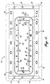
- FIGURE 4 is a side view of the assembly of FIGURE 1;
- FIGURE 5 is a detail cross-sectional view taken along lines 5-5 in FIGURE 4; and
- FIGURE 6 is a detail cross-sectional view taken along lines 6-6 in FIGURE 4.
-
- FIGURE 1 is a perspective view of one embodiment of a
decompression panel assembly 12 formed in accordance with the present invention. The assembly is shown installed in a bulkhead (i.e., more generally, a separation structure 14) that divides a cargo bay and an electronics bay. The view of FIGURE 1 is taken from the cargo bay, looking forward. This particular separation structure and inter-compartment location was selected for illustrative purposes only. The assembly may be secured through other separation structures in an aircraft or space vehicle at locations in which sudden decompression may be required between adjacent compartments. - Referring to FIGURE 2, the
decompression panel assembly 12 generally includes aretaining ring 22, a fire resistantpressure relief panel 24, and asupport pan 26 having anopening 28. During normal use, thepressure relief panel 24 covers the support pan opening 28 and is held in place by theretaining ring 22. The pressure relief panel effectively forms a substantially airtight seal around the opening 28 to resist the passage of flame or smoke from one adjacent compartment to the next. Should the pressure difference between compartments change rapidly, theretaining ring 22 flexes slightly to allow thepressure relief panel 24 to quickly and fully release from theassembly 12 and reveal thesupport pan opening 28, thereby allowing pressure to quickly equalize between adjacent compartments. Thepanel assembly 12 optionally includes agrill 30 to prohibit the pressure relief panel from being unintentionally dislodged (as might easily happen from luggage or personnel moving about in the cargo bay.) - In more detail, the
support pan 26 is a rectangularly shaped planar member having afirst surface 36 and a second surface 34 (see FIGURE 3.) As shown in FIGURE 3, theopening 28 is generally positioned in the center of the pan. It is preferable to also use a rectangular or square opening, and, if possible, to orient theassembly 12 in the separation structure, so that the plane of the assembly is upright and the assembly's longitudinal axis is lateral as illustrated in FIGURE 1. This orientation helps to further reduce the spread of fire between compartments by providing the least amount of vertical distance available for a flame to propagate. Thesupport pan 26 is preferably formed by machining or casting a heat tolerant material, e.g., aluminum, titanium, cobalt, steel, etc. If aluminum is selected, it should be increased in gauge thickness to counteract any metal degradation effects during a fire. An average support pan thickness of about 0,38cm (0.15 inches) to about 0,51cm (0.20 inches) has been shown to work well. - The
decompression panel assembly 12 is a one-way decompression relief panel, i.e., thepressure relief panel 24 is intended to fully release in one direction. In FIGURES 1-4, the support pan second surface 34 (shown best in FIGURE 2) is the side that faces thehigh pressure compartment 39. The support pan first surface 36 (shown best in FIGURE 3) is the side that faces thelow pressure compartment 41. Shown in FIGURE 1, thesupport pan 26 is installed in theseparation structure 14 using a number offasteners 42. Thefasteners 42 are inserted through the support pan and edge seals 46, through holes in theseparation structure 14, and into the capped receptacles common to the separation structure on the low pressure compartment side. The edge seals 46 keep the pressure relief assembly in substantially airtight contact with the separation structure. Theseals 46 are preferably made of a heat resistant, nonflammable material, such as silicone. - It is important that the
support pan fasteners 42 are connected to portions of theseparation structure 14 that are themselves strong enough to maintain their shape and position during a rapid decompression event. Exemplary structures include support stanchions, contour rails, intercostals, floor beams, etc.Preferred fasteners 42 include cadmium steel quarter-turn stud assemblies having a pin, snap ring, and mating grommet. These types of fasteners are preferred because they allow quick and easy removal of the decompression panel assembly should the need arise, e.g., for maintenance or compartment access. - Referring to FIGURE 3, the
decompression panel assembly 12 for this application further includes cappedreceptacles 48 positioned near the support pan's 26 upper and lower side edges. The capped receptacles attach adjacent panel partitions 50 (see FIGURE 1) above and below the decompression panel assembly. - Referring to FIGURE 2, the support pan
second surface 34 includes aperipheral flange 54 extending normally outward therefrom for use in connecting thegrill 30 to thesupport pan 26. Theperipheral flange 54 is made of a heat tolerant nonflammable material integrally formed with the other support pan portions. A preferred grill material is 7050-T7451 aluminum. Thegrill 30 has a depth that is approximately equal to the depth of the support panperipheral flange 54. The grill is sized slightly smaller than the area bounded by theperipheral flange 54. Thegrill 30 therefore inserts into theflange 54 and is held bymultiple grill fasteners 56 passed through theperipheral flange 54 and into side surfaces 35 of thegrill 30. Thefasteners 56 shown in FIGURE 2 include titanium hex head screw bolts, cadmium plated countersink washers, and steel cadmium plated nut plates. The nut plates are riveted to thegrill 30 and are part of its assembly. Both theperipheral flange 54 and the grill side surfaces 35 include secondary pressure relief holes 58 to permit air to pass into the support pan opening 28 in the event the outer grill surface is obstructed by foreign objects. - Referring to FIGURE 3, the support pan
first surface 36 includes arecess 62 that extends around thepan opening 28 and has a width that is greater than its depth. Referring to FIGURE 5, therecess 62 is bounded at the support pan opening by a raised portion 64 (a bull nose is shown) that extends normally outward from the recess surface. Circular integral spacing mounts 66 are located at spaced intervals along therecess 62 and extend outward from the support pan recess surface a distance slightly less than the distance extended outward by thebull nose 64. Ahole 68 is located through thesupport pan 26 at eachintegral spacing mount 66. - Still referring to FIGURE 5, a nonflammable, noncompressed
inner seal 70 made from silicone foam rubber is positioned within therecess 62 and serves as an ablatant heat sink to further diminish the heat transferred from thesupport pan 26 to the retainingring 22. Theinner seal 70 has a thickness approximately equal to the recess depth. Seal holes 72 are provided along theinner seal 70 to accommodate the integral spacing mounts 66. During use, theseal 70 is preferably not compressed or pinched by the retaining ring and the support pan. - The
support pan 26 further includes anouter ring ridge 76 that surrounds therecess 62. Between therecess 62 and theouter ring ridge 76 is a steppedindex ring surface 78. The retainingring 22 is a non-formed sheet metal part profiled slightly smaller in size than the area bounded by theouter ring ridge 76. During normal use, the retainingring 22 is positioned adjacent to thesupport pan 26 such that the retaining ring's outer edge is indexed by theouter ring ridge 76, and the retaining ring's profiled inner edge is positioned near thebull nose 64. The retaining ring contacts thesupport pan 26 at the integral spacing mounts 66 and the steppedsurface 78. The retainingring 22 is held in this position via conventional bolt/nutcombination type fasteners 80 inserted through the connection mount holes 68. - As shown best in FIGURES 5 and 6, the
pressure relief panel 24 is positioned over thesupport pan opening 28 and is held in place about its periphery by a clamping force provided between the retainingring 22 and the supportpan bull nose 64. The clamping force is created when the retainingring 22 closely contacts the integral spacing mounts 66. Since themounts 66 extend outward slightly less distance than thebull nose 64 and the retainingring 22 has some rigidity, the retainingring 22 tends to push against thebull nose 64, thus effectively forming a clamp. Because most of thepressure relief panel 24 periphery is so held (with exceptions discussed below), thedecompression panel assembly 12 acts as an oxygen and smoke barrier to aid in stopping fire hazards from spreading between compartments. - Equally important, is the ability of a
decompression panel assembly 12 formed in accordance with the present invention to quickly release from the clamping force during a rapid decompression event. To ensure a satisfactory response, the retainingring 22 is segmented (see FIGURE 4) in a manner that permits the ring to flex or twist within the elastic range in response to pressure differences between adjacent compartments. In so flexing, portions of the retaining ring move laterally outward an amount sufficient to reduce the clamping force provided by the retainingring 22 and thebull nose 64 at that location, thereby releasing a portion of thepressure relief panel 24. Once even a small portion of thepressure relief panel 24 is dislodged, the entire panel is easily suctioned out of the assembly and into thelow pressure compartment 41. After thepressure relief panel 24 has fully released, the support pan opening 28 is exposed and allows rapid equalization of pressure between adjacent compartments. Optional measures may be taken to reduce or add to the amount of clamping force provided between the retainingring 22 and thebull nose 64, such as polishing the bull nose, altering the gauge thickness of the retainingring 22, altering the height of the integral spacing mounts. - In the embodiments of FIGURES 1-6, the retaining
ring 22 is a single nonfrangible member having a number of segments orfingers 84 formed betweenslits 86 that are located at intervals along the inner edge of the retainingring 22. The ring inner edge includescurved comers 88 at each slit 86 so that the slit edges do not catch on one another. Stress relief holes 90 are recommended to be formed at the slit's inner end to prevent crack propagation. The various dimensions of the slits will vary depending on the response characteristics required in a particular application. - The retaining
ring 22 is formed of a fire resistant material having a melting temperature that is much higher than the temperature of a fire anticipated for either adjacent compartment. Nickel chromium stainless steel 17-7PH has been shown to work well. Thepressure relief panel 24 is formed of a heat and fire resistant material that is also flexible, e.g., BMS 8-223 fiberglass, etc. The preferred ring is nonfrangible, that is it will not break during a decompression event, but will instead only flex. Both thepressure relief panel 24 and retainingring 22 should be sized to provide the appropriate amounts of flexibility and rigidity. In one test assembly, a pressure relief panel of 0,053cm (0.021 inches) having 0,51cm (0.2 inches) of its outer periphery sandwiched between the support pan bull nose and the retaining ring worked well. A retaining ring of 0,041cm (0.016 inches) thickness produced a lateral movement of 0,081cm (0.032 inches) which caused thepressure relief panel 24 to release in less than one second after a rapid decompression event. - To aid in centering the
pressure relief panel 24 during assembly, a number of index pins 94 are provided between the retainingring 22 and thesupport pan 26 at locations corresponding to the desired location of the relief panel's outer edge, as shown best in FIGURES 4 and 6. The number and location of index pins 94 must still allow a number of retainingring fingers 84 to flex. Otherwise, thepressure relief panel 24 will not release properly. Depending on the precise component sizes, it may be desirable to form small, semicircular cutouts (not shown) along the inner edge of the inner seal and the outer edge of the pressure relief panel to negate any compression acting on the seal from the retainingring 24. In any design, it is important that the index pins 94 do not pinch, catch, or bind thepressure relief panel 24 or the retainingring 22. The index pins shown in FIGURES 1, 4 and 6 include titanium screws, cadmium plated steel countersink washers, self-locking cadmium steel plated nuts, and cadmium steel plated flat washers. - The
decompression panel assembly 12 is formed by the following steps. The index pins 94 are connected to the support pan. Theinner seal 70 is placed within thesupport pan recess 62. The fireresistant pressure panel 24 is placed over the support pan opening 28 to contact thebull nose 64. The panel peripheral edge is aligned using the index pins 94. The retainingring 22 is positioned on top of the fire resistantpressure relief panel 24 and the inner seal, with the index pins 94 protruding through retaining ring clearance holes 95 (see FIGURES 4 and 6.) The retaining ring is positioned within the bounds of theouter ring ridge 76, contacting the steppedindex ring surface 78. Thefasteners 80 are installed at eachmount hole 68 to connect the retainingring 22 with thesupport pan 26. Thegrill 30 is inserted into the support panperipheral flange 54 and is held there by thegrill fasteners 56 which passed through theflange 54 and into the side surfaces 35 of thegrill 30. The edge seals 46, quarterturn stud assemblies 42, and cappedreceptacles 48 are attached to the support pan. The decompression assembly is placed in theseparation structure 14, and theadjacent panels 50 are installed. - As will be appreciated by those skilled in the art, a panel assembly formed in accordance with the present invention provides a fast, full-release pressure relief system that is fire resistant. While the preferred embodiment of the invention has been illustrated and described, it will be appreciated that various changes can be made therein without departing from the scope of the invention, as defined in the appended claims.
Claims (23)
- A decompression panel assembly (12) for use in a separation structure, the panel assembly (12) comprising:(a) a support pan (26) having a first surface (36), an opening (28), and a raised portion (64) surrounding the periphery of the opening (28) and extending outwardly, away from the first surface (36);(b) a pressure relief panel (24) sized larger than the support pan opening (28); and(c) a retaining ring (22) connecting to the support pan (26) at the opening (28), the pressure relief panel (24) being located between the raised portion (64) and the retaining ring (22), the connection of the retaining ring (22) to the support pan (26) providing a clamping force on the pressure relief panel (24); the retaining ring (22) including a number of fingers (84) arranged to permit the retaining ring (22) to flex during a decompression event thus allowing the pressure relief panel (24) to fully detach from the assembly (12).
- A decompression panel assembly (12) according to claim 1, wherein the retaining ring (22) is nonfrangible.
- A decompression panel assembly (12) according to claim 1 or 2, wherein the contacts between the retaining ring (22), the pressure relief panel (24), and/or the raised portion (64) are substantially airtight contacts.
- A decompression panel assembly (12) according to claim 1, 2 or 3, wherein the pressure relief panel (24) is sized only slightly larger than the support pan opening (28), the decompression panel assembly (12) further including a number of index pins (94) interconnected between the retaining ring (22) and the support pan (26) for aligning the pressure relief panel (24) within the clamp provided by the retaining ring (22) and the raised portion (64).
- A decompression panel assembly (12) for use in an aircraft separation structure, the panel assembly (12) comprising :(a) a support pan (26) having a first surface (36), an opening (28), and a raised portion (64) surrounding the periphery of the opening (28) and extending outwardly, away from the first surface (36);(b) a pressure relief panel (24) shaped similar to the support pan opening shape; and(c) a nonfrangible retaining ring (22) including an inner periphery having a number of spaced-apart slits (86) extending part way into the retaining ring (22) and an outer periphery; the retaining ring (22) being connected to the support pan (26); the pressure relief panel (24) being held between the support pan (26) raised portion (64) and the retaining ring (22); wherein during a rapid decompression event the slits (86) allow the retaining ring (22) to flex slightly outward to reduce the holding force applied to the pressure relief panel (24).
- A decompression panel assembly (12) according to claim 5, further including an inner seal (70) located between the retaining ring (22) and the support pan (26), the inner seal (70) for providing an ablatant heat sink.
- A decompression panel assembly (12) according to claim 6, wherein the press relief panel (24) is sized only slightly larger than the support pan opening (28), the decompression panel assembly (12) further including a number of index pins (94) interconnected between the retaining ring (22) and the support pan (26) for aligning the pressure relief panel (24).
- A decompression panel assembly (12) according to any of claims 1-7, wherein the support pan (26) further includes a second surface (34), the panel assembly (12) further including a grill (30) attached to the support pan second surface (34), the grill (30) covering the support pan opening (28).
- A decompression panel assembly (12) according to claim 8, wherein the grill (30) is formed from machined aluminum.
- A decompression panel assembly (12) according to claim 8 or 9, wherein the support pan (26) includes a flange (54) extending normally from the second surface (34), the grill (30) being inserted into and/or attached to the flange (54).
- A decompression panel assembly (12) according to claim 10, wherein the pressure relief panel (24) is sized slightly larger than the support pan opening (28), the decompression panel assembly (12) further including a number of index pins (94) which protrude through the retaining ring (22) and are fastened to the support pan (26) for aligning the pressure relief panel (24) between the retaining ring (22) and the raised portion (64).
- A decompression panel assembly (12) according to any of claims 1-11, wherein the pressure relief panel (24) is formed of a fire resistant fiberglass.
- A decompression panel assembly (12) according to any of claims 1-12, wherein the retaining ring (22) is formed of nickel chromium stainless steel.
- A decompression panel assembly (12) according to any of claims 1-13, wherein the raised portion (64) has a cross-sectionally curved shape.
- A decompression panel assembly (12) according to any of claims 10-14 when dependent on claim 10, wherein the grill (30), the support pan opening (28), the peripheral flange (54), the pressure relief panel (24), and the retaining ring (22) are each shaped as one of a rectangle and/or a square.
- A decompression panel assembly (12) for use in an aircraft separation structure, the assembly (12) comprising:(a) a support pan (26) having a first surface (36), an opening (28), and a raised portion (64) surrounding the periphery of the opening (28) and extending outwardly, away from the first surface (36);(b) a pressure relief panel (24) sized to cover the support pan opening (28), and(c) a retaining ring (22) connecting to the support pan (26) at the opening (28), the pressure relief panel (24) being located between the raised portion (64) and the retaining ring (22), the retaining ring (22) being formed as a single unit having a number of segments (84); and(d) an inner seal (70) positioned between the support pan (26) and the retaining ring (22), the inner seal (70) acting as a heat sink; wherein during a rapid decompression event the retaining ring (22) flexes outward to allow the pressure relief panel (24) to fully detach from the assembly (12).
- A decompression panel assembly (12) according to any of claims 6-15 when dependent on claim 6, or to claim 16, wherein the support pan first surface (36) includes a recess (62) positioned around the raised portion (64) and the inner seal (70) is positioned in the recess (62).
- A decompression panel assembly (12) according to claim 17, wherein the support pan first surface (36) further includes a index ring surface (78) located around the recess (62) and an outer ring ridged (76) located around the index ring surface (78); the retaining ring (22) being positioned on the support pan (26) within the outer ring ridge (76) and being supported by the index ring surface (78).
- A decompression panel assembly (12) according to claim 16, 17 or 18, wherein the retaining ring (22) is connected to the support pan (26) by a number of spaced apart fasteners (80).
- A decompression panel assembly (12) according to any of claims 1-19, wherein the connection between the pressure relief panel (24) and the support pan (26) is substantially airtight.
- A decompression panel assembly (12) according to any of claims 6-15 when dependent on claim 6, or to claims 16-20 when dependent on claim 16 or claim 6, wherein the inner seal (70) is formed from fiberglass.
- A decompression panel assembly (12) according to any of claims 16-21, wherein the support pan (26) includes a second surface (34) that is opposite the first surface (36), the panel assembly (12) further including a grill (30) attached to the support pan second surface (34), the grill (30) for preventing objects from dislodging the pressure relief panel (24).
- A decompression panel assembly (12) according to any of claims 8-15 and 17-21 when dependent on claim 8, or to claim 22, wherein the grill (30) includes a number of secondary pressure relief holes (58).
Applications Claiming Priority (2)
| Application Number | Priority Date | Filing Date | Title |
|---|---|---|---|
| US08/910,576 US6029933A (en) | 1997-08-01 | 1997-08-01 | Fire resistant pressure relief panel assembly |
| US910576 | 1997-08-01 |
Publications (3)
| Publication Number | Publication Date |
|---|---|
| EP0894709A2 EP0894709A2 (en) | 1999-02-03 |
| EP0894709A3 EP0894709A3 (en) | 2001-02-07 |
| EP0894709B1 true EP0894709B1 (en) | 2003-11-19 |
Family
ID=25429013
Family Applications (1)
| Application Number | Title | Priority Date | Filing Date |
|---|---|---|---|
| EP98202609A Expired - Lifetime EP0894709B1 (en) | 1997-08-01 | 1998-08-03 | Fire resistant pressure relief panel assembly |
Country Status (5)
| Country | Link |
|---|---|
| US (1) | US6029933A (en) |
| EP (1) | EP0894709B1 (en) |
| CN (1) | CN1087701C (en) |
| CA (1) | CA2244069C (en) |
| DE (1) | DE69819823T2 (en) |
Families Citing this family (33)
| Publication number | Priority date | Publication date | Assignee | Title |
|---|---|---|---|---|
| US6435455B1 (en) * | 1997-08-01 | 2002-08-20 | The Boeing Company | Flow-efficient, static pressure-shielding, fire-resistant decompression panel assembly |
| US6129312A (en) * | 1997-09-26 | 2000-10-10 | The Boeing Company | Aircraft decompression vent assembly |
| US6601356B2 (en) * | 1998-09-03 | 2003-08-05 | Snyder National Corporation | Connector frame for ventilation opening |
| US20040172889A1 (en) | 2003-03-04 | 2004-09-09 | Tom Eijkelenberg | Unitary overpressure vent panel structure |
| US6712316B2 (en) * | 2002-08-01 | 2004-03-30 | The Boeing Company | Snap-on sidewall assembly |
| NZ527968A (en) * | 2003-09-01 | 2006-07-28 | H2Safe Llc | Storage vessel |
| DE102006020147A1 (en) * | 2006-05-02 | 2007-11-15 | Airbus Deutschland Gmbh | Fire barrier for aircraft to protect from burn-out between cargo and passenger cab, has burnout-safety-panel for blocking fire in partition wall area of aircraft body |
| DE102006044093B4 (en) * | 2006-09-20 | 2009-01-22 | Airbus Deutschland Gmbh | Disk replacement to fill a window frame |
| DE102007011627A1 (en) * | 2007-01-23 | 2008-07-31 | Airbus Deutschland Gmbh | Interior lining for an aircraft |
| DE102007061433B4 (en) * | 2007-12-20 | 2012-10-25 | Airbus Operations Gmbh | Improved decompression device with adjustable trigger pressure |
| DE102008016104A1 (en) * | 2008-03-28 | 2009-10-08 | Airbus Deutschland Gmbh | Breathable aircraft fuselage |
| US8240604B2 (en) * | 2009-12-14 | 2012-08-14 | Be Intellectual Property, Inc. | Fireproof bidirectional decompression panel |
| US8651924B1 (en) * | 2010-05-06 | 2014-02-18 | The Boeing Company | Interlocking vent assembly for equalizing pressure in a compartment |
| AT510153B1 (en) | 2010-10-19 | 2012-02-15 | Facc Ag | decompression |
| FR3005936B1 (en) * | 2013-05-24 | 2016-08-19 | Airbus Operations Sas | SUPPORT PLATE FOR PASSING SYSTEMS BETWEEN TWO ZONES WITH DIFFERENT PRESSURIZATIONS OF AN AIRCRAFT. |
| US9440744B2 (en) | 2013-10-17 | 2016-09-13 | The Boeing Company | Decompression panel assembly and method of equalizing air pressure differential |
| US9566759B2 (en) * | 2013-10-25 | 2017-02-14 | The Boeing Company | Decompression panel for use in an aircraft assembly |
| USD726093S1 (en) * | 2013-10-25 | 2015-04-07 | The Boeing Company | Decompression panel |
| US10071795B2 (en) | 2013-10-25 | 2018-09-11 | The Boeing Company | Clamp device for use with a decompression panel in an aircraft assembly |
| US9233747B2 (en) * | 2013-10-25 | 2016-01-12 | The Boeing Company | Decompression panel for use in an aircraft assembly |
| US9499251B2 (en) | 2013-10-25 | 2016-11-22 | The Boeing Company | Decompression panel for use in an aircraft |
| USD817851S1 (en) | 2014-03-28 | 2018-05-15 | The Boeing Company | Decompression panel |
| EP3209515B1 (en) | 2014-10-24 | 2018-12-05 | H2Safe, LLC | Fail-safe containment device for containing volatile fluids |
| US10494079B2 (en) | 2016-03-30 | 2019-12-03 | The Boeing Company | Decompression panel assembly and methods of manufacturing the same |
| US10279887B2 (en) | 2016-06-06 | 2019-05-07 | The Boeing Company | Decompression panel assembly and methods of assembling the same |
| US10399660B2 (en) * | 2016-06-06 | 2019-09-03 | The Boening Company | Decompression panel assembly and methods of assembling the same |
| DE102017221444B4 (en) * | 2017-11-29 | 2019-09-05 | Premium Aerotec Gmbh | Pressure bulkhead for an aircraft |
| US11008089B2 (en) * | 2018-10-24 | 2021-05-18 | Gulfstream Aerospace Corporation | Fireproof pressure relief assembly |
| US11577815B2 (en) * | 2020-01-30 | 2023-02-14 | Textron Innovations Inc. | Isogrid patterns for structural aircraft panels |
| CN112577113B (en) * | 2020-12-25 | 2025-01-24 | 中国人民解放军63921部队 | A new air outlet device with typhoon protection function |
| CN113753258B (en) * | 2021-09-22 | 2023-07-07 | 中国航空工业集团公司西安飞机设计研究所 | Bolt-mounted aircraft windshield glass small deflection calculation method |
| CN114840917B (en) * | 2022-04-14 | 2022-11-22 | 清华大学 | Fire-fighting aircraft safety constraint boundary construction method and system |
| FR3158703A1 (en) * | 2024-01-26 | 2025-08-01 | Airbus Operations | Decompression hatch provided with an elastomer part for an aircraft and internal wall of an aircraft provided with such a decompression hatch. |
Family Cites Families (10)
| Publication number | Priority date | Publication date | Assignee | Title |
|---|---|---|---|---|
| US4498261A (en) * | 1981-12-07 | 1985-02-12 | Continental Disc Corporation | Low pressure venting panel |
| US4454686A (en) * | 1982-09-28 | 1984-06-19 | Stapenell Ralph H | Pressure-relieving closure panel |
| US4646993A (en) * | 1985-03-04 | 1987-03-03 | The Boeing Company | Sidewall vent valves for a convertible compartment aircraft |
| DE3715328C1 (en) * | 1987-05-08 | 1988-08-18 | Messerschmitt Boelkow Blohm | Decompression panel |
| DE3922025C1 (en) * | 1989-07-05 | 1990-08-09 | Messerschmitt-Boelkow-Blohm Gmbh, 8012 Ottobrunn, De | |
| US5069401A (en) * | 1989-11-15 | 1991-12-03 | The Boeing Company | Compartment partition and pressure relief door therefor |
| DE4002447C1 (en) * | 1990-01-27 | 1991-03-14 | Deutsche Airbus Gmbh, 2103 Hamburg, De | Decompression panel esp. for aircraft - consists of plate which is releasably held in de-compression opening and consists of two inter-strapped plate parts |
| DE4216277C2 (en) * | 1992-05-16 | 1994-12-01 | Deutsche Aerospace Airbus | Decompression panel for partitions and floors of passenger and cargo compartments in aircraft |
| US5461831A (en) * | 1993-12-29 | 1995-10-31 | Eastman Kodak Company | Assemblage and method for relieving overpressure in an enclosure |
| DE4403896C1 (en) * | 1994-02-08 | 1995-09-14 | Daimler Benz Aerospace Airbus | Holder for decompression panel in wall or floor opening of passenger or freight chamber of aircraft |
-
1997
- 1997-08-01 US US08/910,576 patent/US6029933A/en not_active Expired - Lifetime
-
1998
- 1998-07-27 CA CA002244069A patent/CA2244069C/en not_active Expired - Lifetime
- 1998-08-01 CN CN98117596A patent/CN1087701C/en not_active Expired - Fee Related
- 1998-08-03 EP EP98202609A patent/EP0894709B1/en not_active Expired - Lifetime
- 1998-08-03 DE DE69819823T patent/DE69819823T2/en not_active Expired - Lifetime
Also Published As
| Publication number | Publication date |
|---|---|
| CN1087701C (en) | 2002-07-17 |
| EP0894709A3 (en) | 2001-02-07 |
| CA2244069C (en) | 2007-03-13 |
| DE69819823D1 (en) | 2003-12-24 |
| CA2244069A1 (en) | 1999-02-01 |
| US6029933A (en) | 2000-02-29 |
| DE69819823T2 (en) | 2004-04-15 |
| CN1215681A (en) | 1999-05-05 |
| EP0894709A2 (en) | 1999-02-03 |
Similar Documents
| Publication | Publication Date | Title |
|---|---|---|
| US6029933A (en) | Fire resistant pressure relief panel assembly | |
| EP1186531B1 (en) | Aircraft decompression panel assembly | |
| US5871178A (en) | Decompression panel for aircraft partition | |
| EP1196325B1 (en) | Monolithic structure with redundant load paths | |
| US8714483B2 (en) | Decompression device and decompression system | |
| US4899960A (en) | Decompression panel for aircraft partition | |
| EP2512914B1 (en) | Fireproof bidirectional decompression panel | |
| US6129312A (en) | Aircraft decompression vent assembly | |
| US5085017A (en) | Decompression panel for a separation device in an aircraft | |
| US6138949A (en) | Main rotor pylon support structure | |
| US20180016008A1 (en) | Aircraft Monument Floor Mounting System | |
| US6010286A (en) | Apparatus for rigidly retaining cargo | |
| US7094968B2 (en) | Fitting for a liquid-tight cable leadthrough | |
| US5606829A (en) | Mounting device for a decompression panel | |
| US20090272849A1 (en) | Frame element, aircraft component assembly system and method of fitting a component in an aircraft | |
| US4552325A (en) | Emergency smoke disposal system for pressurized aircraft | |
| EP3569502A1 (en) | Flexible wall mount for aircraft cabin seat | |
| CN204846357U (en) | Pressure relief device for aircraft cargo compartment | |
| EP3403921B1 (en) | Compartmental barrier with decompression panels | |
| EP1462347B2 (en) | Cargo liner installation | |
| EP2054296B1 (en) | Frame element, aircraft component assembly system and method of fitting a component in an aircraft | |
| US7562846B2 (en) | Window retaining system | |
| US20060191221A1 (en) | Fire stop wall unit | |
| CN214566108U (en) | Decompression opening structure of cabin separation plate of aircraft sealed cabin | |
| US20240228009A1 (en) | Systems and methods for protecting surfaces of components within an internal cabin of a vehicle |
Legal Events
| Date | Code | Title | Description |
|---|---|---|---|
| PUAI | Public reference made under article 153(3) epc to a published international application that has entered the european phase |
Free format text: ORIGINAL CODE: 0009012 |
|
| AK | Designated contracting states |
Kind code of ref document: A2 Designated state(s): DE FR GB |
|
| AX | Request for extension of the european patent |
Free format text: AL;LT;LV;MK;RO;SI |
|
| PUAL | Search report despatched |
Free format text: ORIGINAL CODE: 0009013 |
|
| AK | Designated contracting states |
Kind code of ref document: A3 Designated state(s): AT BE CH CY DE DK ES FI FR GB GR IE IT LI LU MC NL PT SE |
|
| AX | Request for extension of the european patent |
Free format text: AL;LT;LV;MK;RO;SI |
|
| 17P | Request for examination filed |
Effective date: 20010716 |
|
| AKX | Designation fees paid |
Free format text: DE FR GB |
|
| GRAH | Despatch of communication of intention to grant a patent |
Free format text: ORIGINAL CODE: EPIDOS IGRA |
|
| GRAS | Grant fee paid |
Free format text: ORIGINAL CODE: EPIDOSNIGR3 |
|
| GRAA | (expected) grant |
Free format text: ORIGINAL CODE: 0009210 |
|
| AK | Designated contracting states |
Kind code of ref document: B1 Designated state(s): DE FR GB |
|
| REG | Reference to a national code |
Ref country code: GB Ref legal event code: FG4D |
|
| REF | Corresponds to: |
Ref document number: 69819823 Country of ref document: DE Date of ref document: 20031224 Kind code of ref document: P |
|
| ET | Fr: translation filed | ||
| PLBQ | Unpublished change to opponent data |
Free format text: ORIGINAL CODE: EPIDOS OPPO |
|
| PLBI | Opposition filed |
Free format text: ORIGINAL CODE: 0009260 |
|
| PLAX | Notice of opposition and request to file observation + time limit sent |
Free format text: ORIGINAL CODE: EPIDOSNOBS2 |
|
| 26 | Opposition filed |
Opponent name: AIRBUS SAS Effective date: 20040819 |
|
| PLAX | Notice of opposition and request to file observation + time limit sent |
Free format text: ORIGINAL CODE: EPIDOSNOBS2 |
|
| PLBB | Reply of patent proprietor to notice(s) of opposition received |
Free format text: ORIGINAL CODE: EPIDOSNOBS3 |
|
| PLAY | Examination report in opposition despatched + time limit |
Free format text: ORIGINAL CODE: EPIDOSNORE2 |
|
| PLAH | Information related to despatch of examination report in opposition + time limit modified |
Free format text: ORIGINAL CODE: EPIDOSCORE2 |
|
| PLAH | Information related to despatch of examination report in opposition + time limit modified |
Free format text: ORIGINAL CODE: EPIDOSCORE2 |
|
| PLCK | Communication despatched that opposition was rejected |
Free format text: ORIGINAL CODE: EPIDOSNREJ1 |
|
| PLBN | Opposition rejected |
Free format text: ORIGINAL CODE: 0009273 |
|
| STAA | Information on the status of an ep patent application or granted ep patent |
Free format text: STATUS: OPPOSITION REJECTED |
|
| 27O | Opposition rejected |
Effective date: 20070425 |
|
| REG | Reference to a national code |
Ref country code: FR Ref legal event code: PLFP Year of fee payment: 19 |
|
| REG | Reference to a national code |
Ref country code: FR Ref legal event code: PLFP Year of fee payment: 20 |
|
| PGFP | Annual fee paid to national office [announced via postgrant information from national office to epo] |
Ref country code: GB Payment date: 20170829 Year of fee payment: 20 Ref country code: DE Payment date: 20170829 Year of fee payment: 20 Ref country code: FR Payment date: 20170825 Year of fee payment: 20 |
|
| REG | Reference to a national code |
Ref country code: DE Ref legal event code: R071 Ref document number: 69819823 Country of ref document: DE |
|
| REG | Reference to a national code |
Ref country code: GB Ref legal event code: PE20 Expiry date: 20180802 |
|
| PG25 | Lapsed in a contracting state [announced via postgrant information from national office to epo] |
Ref country code: GB Free format text: LAPSE BECAUSE OF EXPIRATION OF PROTECTION Effective date: 20180802 |