EP0894250B1 - Verfahren und einrichtung zum prüfen der festigkeit von stehend verankerten masten - Google Patents
Verfahren und einrichtung zum prüfen der festigkeit von stehend verankerten masten Download PDFInfo
- Publication number
- EP0894250B1 EP0894250B1 EP97922845A EP97922845A EP0894250B1 EP 0894250 B1 EP0894250 B1 EP 0894250B1 EP 97922845 A EP97922845 A EP 97922845A EP 97922845 A EP97922845 A EP 97922845A EP 0894250 B1 EP0894250 B1 EP 0894250B1
- Authority
- EP
- European Patent Office
- Prior art keywords
- mast
- functions
- force
- evaluation unit
- courses
- Prior art date
- Legal status (The legal status is an assumption and is not a legal conclusion. Google has not performed a legal analysis and makes no representation as to the accuracy of the status listed.)
- Expired - Lifetime
Links
Images


Classifications
-
- G—PHYSICS
- G01—MEASURING; TESTING
- G01M—TESTING STATIC OR DYNAMIC BALANCE OF MACHINES OR STRUCTURES; TESTING OF STRUCTURES OR APPARATUS, NOT OTHERWISE PROVIDED FOR
- G01M5/00—Investigating the elasticity of structures, e.g. deflection of bridges or air-craft wings
- G01M5/0041—Investigating the elasticity of structures, e.g. deflection of bridges or air-craft wings by determining deflection or stress
- G01M5/005—Investigating the elasticity of structures, e.g. deflection of bridges or air-craft wings by determining deflection or stress by means of external apparatus, e.g. test benches or portable test systems
- G01M5/0058—Investigating the elasticity of structures, e.g. deflection of bridges or air-craft wings by determining deflection or stress by means of external apparatus, e.g. test benches or portable test systems of elongated objects, e.g. pipes, masts, towers or railways
-
- G—PHYSICS
- G01—MEASURING; TESTING
- G01L—MEASURING FORCE, STRESS, TORQUE, WORK, MECHANICAL POWER, MECHANICAL EFFICIENCY, OR FLUID PRESSURE
- G01L5/00—Apparatus for, or methods of, measuring force, work, mechanical power, or torque, specially adapted for specific purposes
- G01L5/0028—Force sensors associated with force applying means
- G01L5/0033—Force sensors associated with force applying means applying a pulling force
-
- G—PHYSICS
- G01—MEASURING; TESTING
- G01L—MEASURING FORCE, STRESS, TORQUE, WORK, MECHANICAL POWER, MECHANICAL EFFICIENCY, OR FLUID PRESSURE
- G01L5/00—Apparatus for, or methods of, measuring force, work, mechanical power, or torque, specially adapted for specific purposes
- G01L5/0028—Force sensors associated with force applying means
- G01L5/0038—Force sensors associated with force applying means applying a pushing force
Definitions
- the invention relates to a method and a device for checking the Strength of standing anchored masts according to the preamble of the claims 1 or 7.
- the device comprises a power unit, the one force measured continuously via a force sensor in the mast above initiates its ground anchoring, a displacement sensor that the to the introduced Force continuously measuring mast deflection, and an evaluation unit, which both types of measured values are continuously fed.
- the power unit guides you Pressure or tensile force as a test load up to a predetermined value in the mast, the aforementioned measured values in the evaluation unit in a ratio the force is shown depending on the mast deflection. If there is a straight line up to the test load, the mast including its Anchoring found to be in order. It turns out that the straight line in front Reaching the test load in a curved line with a decreasing slope passes, there is a plastic deformation of the mast with the result that the Mast needs to be replaced.
- the procedure and the set-up have proven themselves in practice, since it is hereby the stability and bending strength is possible in a simple and quick way of the mast.
- the bending strength of the mast is also determines whether the mast has received cracks over time Affect lifespan.
- the object of the invention is to provide a method and a device introductory type so that a statement about freedom from cracks or can be achieved by cracking the mast.
- the force-distance values can be a distance as well as an angular path his.
- a feature is that the Gradients of the functions f1 related to the same zero point and f2 as a criterion for a depending on different times Crack enlargement can be evaluated and in the form of a characteristic curve for each mast on one monitor and / or printer connected to the evaluation unit can be documented are.
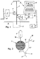
- a mast 1 is anchored 2 in the ground 3 attached.
- the mast 1 is, for example, a light mast, which may be on has at its top end an outrigger la, at the end of which a street lamp 4 is attached.
- a device for testing the strength of the standing anchored mast 1 comprises a power unit 5, for example on a mobile, schematically indicated vehicle 6 can be attached, a force sensor 7, which located between the power unit 5 and the mast 1, one preferably as Distance sensor designed path sensor 8, which is vertical in the same Test level of unit 5 and force sensor 7, but on the other side the mast 1 is arranged, and one with the force sensor and the displacement sensor interconnected evaluation unit 9.
- This evaluation unit comprises a computer 10, e.g. a personal computer with a monitor 11 and / or a printer 12 is connected.
- a transmitter 13 is provided, which signals the Force sensor 7 and displacement sensor 8 in processed form to computer 10 feeds.
- the more precise, not further decisive structure of the above The device described can be designed as it is in DE-U-94 04 664 is described. It is also possible e.g. B. to use two displacement sensors 8, whose measured values are averaged so that the averaged value for the characteristic curve determination is used.
- the evaluation unit 9 is designed such that both the pressure force measurement results as well as the tensile force measurement results in the respective test level and are displayed together in relation to the associated mast deflection.
- the unit 9 can also include comparison circuits for reference characteristic curves are determined. The instantaneous characteristic curves obtained are thus included the corresponding reference characteristics in the evaluation unit automatically compared and the result optically (symbolically or alphabetically) preferred displayed on the monitor and / or printer. Alternatively or additionally, this can be done Result can also be given acoustically.
- the mast is tested for bending strength in particular as follows.
- a first vertical examination level is selected, in which the Mast 1 by means of a tensile force and a compressive force that is above the mast anchor 2 attack at a predetermined position on the mast, subjected to bending becomes.
- a level will be chosen in which the The main load on the mast is.
- the load on the Masts taken into account by wind forces.
- the first vertical test plane is indicated in FIG. in which the main loading forces of the anchored mast also act. It is assumed that initially a compressive force 15 is applied continuously to the mast is exercised. The at a predetermined point above the anchor 2 to the Mast 1 connected displacement sensor 8 detects in this example the corresponding Force F associated with lateral path deflections S. Both Values are simultaneously or almost simultaneously and continuously in the transmitter 13 entered, which in turn prepares them accordingly in the computer 10 enters. This processes the incoming according to a program Measured values, i.e. he puts them in a relationship, usually as a function f on the force F as a function of the mast deflection S. This creates a instantaneous characteristic curve 16, as can be seen on the monitor 11. Alternatively or in addition, this characteristic 16 can also be connected to the computer 10 Printer 12 can be printed out and thus documented.
- a tensile force 17 is then applied in the same vertical test plane 14 continuously exercised on the mast 1.
- a current characteristic curve 18 is again obtained, like the graphic on shows the monitor 11.
- This characteristic curve can have the same slope as the characteristic curve 16 previously obtained, but it can also deviate from how it is shown.
- This characteristic curve can also be printed out on the printer 12.
- both characteristic curves 16, 18 are compared with one another or with the reference values the comparison circuits automatically compared and the respective Result displayed.
- the mast 1 is now like in at least a second vertical examination level 19 checked above.
- This second examination level preferably runs in the right angle to the first vertical test level 14. Again, two receive current characteristics that are displayed on the monitor 11 and / or can be permanently documented with the printer 12. If the mast in the two examination levels 14 and 19 has been examined, is therefore a very good statement regarding the entire mast circumference with regard to a possible Given cracks.
- Characteristic curve 20 as a straight line, namely this line runs in a straight form up to to reach the test load P. Then the mast is subjected to a bending load subjected to a pulling force, and then you get another momentary Characteristic curve 21. This characteristic curve also runs straight up to the test load P.
- the two characteristic curves 20 and 21 are only next to one another for the sake of clarity shown; in fact, they start from the same zero point, and in the present one Case they coincide.
- Both characteristics 20 and 21 have the same slope over their entire length C on. These characteristic curves are generated by means of comparison circuits with reference characteristic curves of the mast compared to the values of a completely intact Mastes correspond.
- FIG. 3 it is assumed that the stored in the program of the computer 10 and also displayed on the monitor 11 Reference characteristic curves with the characteristic curves 20 obtained by the test and 21 match in terms of their slope and course. It follows, that the tested mast is in order and therefore shows no crack. Since both Characteristic curves have the same course here is a comparison with reference characteristic curves not absolutely necessary.
- Figure 4 shows a test result of another mast (it can of course also the examination result of the first mast in a second examination level). It it can be seen that the current tractive force characteristic curve 22 has a smaller gradient C1 has a greater gradient than the current pressure force characteristic curve 23 C2. It is assumed that the slope and the course of the Characteristic curve 23 coincides with the corresponding reference characteristic curve, so that the tested mast is okay on this point and at least no crack the side on which the pressure force attacked.
- the characteristic curve 22 with the smaller slope C1 results in comparison to the characteristic curve 23 a crack in the mast, since the mast, as already mentioned, is present of a crack behaves more elastic. This crack is on that one Circumferential point of the mast, that of the force unit 5, of which the tensile load is assumed. Since the current characteristic curve 22 to Test load P runs straight and still has a relatively large slope, can be assumed that the tested mast still for a certain time may be in operation or replaced at a later date are needed. This later replacement can be based on past experience judge.
- the current characteristic curves 22 and 23 (cf. FIG. 4) from the first test (push and pull) are already shown in FIG. After a certain time t 2 , for example after one year, the next push-pull test is carried out. After this time, a pressure characteristic curve is obtained according to FIG. 5, which overlaps with the corresponding characteristic curve 23. At the corresponding point, the mast is still in order according to the final evaluation signal. With the corresponding train load in the same test level, however, there is an instantaneous train characteristic curve 24 which deviates from the corresponding characteristic curve 22 previously obtained in the first test, that is to say has a smaller gradient C2. The evaluation signal shows that the existing crack has increased at the corresponding point.
- a third test is carried out in the same test level at the same points on the same mast.
- the compressive force characteristic curve obtained coincides with the original characteristic curve 23, with the result that the mast is still without a crack on its corresponding side.
- a further tractive force characteristic curve 25 is obtained, the gradient C3 of which is still less than the gradient C2 of the corresponding characteristic curve 24 of the second test, from which it follows that the crack which has already been determined has become even larger.
- a direct comparison of the remaining signals of the tested mast is already possible from the evaluation signals of these new characteristic curves in a direct comparison.
- the evaluation unit 9 or the computer 10 can be designed such that a time-dependent characteristic curve for changing the gradient of the respective characteristic curves can be calculated from the different slopes of the corresponding characteristic curves according to FIG. 5 obtained.
- a time-dependent characteristic curve N is shown in FIG. 6, which represents the course over time of the gradients on the basis of the changes in the tractive force characteristic curves 22, 24 and 25. It can be seen that the lower end of the gradient change characteristic N Z is very close to a critical value C K. From this a display signal is developed by means of a circuit that the tested mast is to be exchanged shortly. Thus, by means of the characteristic curve N Z according to FIG. 6, a very precise statement about the time of replacement of the tested mast can be achieved.
- the gradient change characteristic curve N Z according to FIG. 6 can also be displayed on the monitor and / or with the Printer documentable.
- the horizontal characteristic curve N D in FIG. 6 also shows optically that no crack in the mast could be found during the compressive force tests.
- FIG. 1 Another example of a mast test is shown in FIG.
- a pressure load Characteristic curve 26 which is composed of at least sections 26a and 26b.
- the first section 26a begins with the slope C4 and runs straight or essentially straight up to a force F1.
- the subsequent one second section 26b also runs straight or essentially straight up to maximum test force FP, but points towards the slope C4 of the first section a steeper slope C5.
- the first section can again consist of several sections (not shown), which are usable Changes in incline are marked and further statements allow for crack damage to the mast.
- the mast is counter-loaded on the same test level, i. H. when using a Traction load, there is a characteristic curve 27, which also consists of at least two sections 27a and 27b can exist. But you can also do it right from the start consist of only a straight or essentially straight line, as is dashed continued with 27c.
- the first section 27a begins with its slope C6, which corresponds to the slope C4 of section 26a or in corresponds essentially to the force F1, which is the second section 27b connects with a slope C7 that is smaller than the initial slope C6.
- the second section can in turn consist of several sections exist (not shown), which are characterized by usable slope changes are and further statements about a crack damage of the mast allow.
- the open crack is opened further and the mast behaves more flexibly from the start than a mast without Crack.
- the slope C6 of the first section 27a of the slope C4 of the Comparative section 26a correspond, as shown, but also less than these be.
- the tractive force characteristic can depend essentially on the crack configuration 27 straight without changing the slope to the maximum test force FP continue, as is indicated by dashed lines at 27c, or it can be about kink the force value F1 such that the slope C7 of the straight or in substantially straight section 27b is smaller than the initial slope C6.
- the evaluation unit 9 is set up in such a way that both the straight characteristic curves 20 to 27 and the slope change characteristic curves N Z can be calculated directly or indirectly from the measured values obtained from the sensors 7 and 8. In any case, both a compressive force characteristic curve and a tensile force characteristic curve are always evaluated and displayed in a suitable manner, so that it can be determined in comparison with one another or with predetermined reference values whether the tested mast has at least one crack or not.
- the above explanation of the proposed device is only to take into account those characteristics, when determining the respective test load is reached. If the test load is not reached, the failure is the mast not necessarily due to a crack in the mast, but z. B. failure to anchor it in the ground. It should also be emphasized again that the mast deflections are also determined by means of angle sensors and accordingly can be processed in the evaluation unit 9.
Description
- Figur 1
- schematisch und stark vereinfacht den Aufbau einer erfindungsgemäßen Einrichtung in Verbindung mit einem zu prüfenden Mast,
- Figur 2
- ein Prüfungsvorgang an einem Mast mit der Einrichtung nach Fig. 1,
- Figuren 3 und 4
- Diagramme, die die momentanen Kennlinien bei einem geprüften Mast zeigen,
- Figur 5
- ein Diagramm, das die momentanen Kennlinien bei einem anderen geprüften Mast zeigen,
- Figur 6
- ein Diagramm, das eine zeitabhängige Kennlinie zeigt, die aus den Prüfungsergebnissen der momentanen Kennlinien nach Figur 5 des anderen Mastes erhalten worden sind, und
- Figur 7
- ein weiteres Diagramm, bei dem abgeknickte Mastprüfungskennlinien erhalten wurden.
Claims (12)
- Verfahren zum Prüfen der Festigkeit von stehend verankerten Masten, gemäß dem in den Mast (1) oberhalb seiner Verankerung (2) ansteigende, mit einem Kraftsensor (7) erfaßbare Zug- und Druckkräfte F eingeleitet werden, um den Mast mit entgegengesetzt gerichteten Biegemomenten zu belasten, wobei mit wenigstens einem oberhalb der Mastverankerung gegen den Mast zur Anlage bringbaren Wegsensor (8) eine aufgrund der Biegemomente auftretende seitliche Auslenkung S des Mastes gemessen wird und wobei die von den Kraft- und Wegsensoren erzeugten Meßwerte für die Kraft F und die Auslenkung S zeitgleich oder fast zeitgleich in einer Auswerteeinheit (9) in bezug auf die Funktionen f = F(S) bzw. f = S(F) verarbeitet werden, und zwar gesondert nach Verläufen der Funktionen f1 für den Druckbelastungsfall und f2 für den Zugbelastungsfall, dadurch gekennzeichnet, daß eine bei elastischer Mastverformung ermittelte Abweichung der Steigung des Verlaufes der Funktion f1 von der Steigung des Verlaufes der Funktion f2 oder von jeweiligen Referenzwerten als Kriterium für zumindest eine Rißbildung im Mast (1) ausgewertet wird.
- Verfahren nach Anspruch 1, dadurch gekennzeichnet, daß eine Divergenz der auf den gleichen Nullpunkt bezogenen geraden oder teilweisen geraden Verläufe der Funktionen f1 und f2 als Kriterium für eine Rißbildung ausgewertet wird.
- Verfahren nach einem der Ansprüche 1 und 2, dadurch gekennzeichnet, daß die Funktionen f1 und f2 optisch gemeinsam auf einem an die Auswerteeinheit (9) angeschlossenen Monitor (11) dargestellt werden.
- Verfahren nach einem der Ansprüche 1 bis 3, dadurch gekennzeichnet, daß der jeweilige Verlauf der Funktionen f1 und f2 mit einem an die Auswerteeinheit (9) angeschlossenen Drucker (12) gemeinsam aufgezeichnet wird.
- Verfahren nach einem der Ansprüche 1 bis 4, dadurch gekennzeichnet, daß die Steigungen (C) der auf den gleichen Nullpunkt bezogenen Verläufe der Funktionen f1 und f2 in Abhängigkeit von unterschiedlichen Zeitpunkten als Kriterium für eine Rißvergrößerung ausgewertet werden.
- Verfahren nach Anspruch 5, dadurch gekennzeichnet, daß die errechneten, zeitabhängigen Steigungen (C) der Verläufe der Funktionen f1 und f2 in Form einer Kennlinie (N) auf einem an die Auswerteeinheit (9) angeschlossenen Monitor (11) angezeigt und/oder mit einem Drucker (12) aufgezeichnet werden.
- Einrichtung zum Prüfen der Festigkeit von stehend verankerten Masten mit einer Krafteinheit (5), mit der in den Mast (1) oberhalb seiner Verankerung (2) ansteigende, mit einem Kraftsensor (7) erfaßbare Zug- und Druckkräfte F einleitbar sind, um den Mast mit entgegengesetzt gerichteten Biegemomenten zu belasten, und mit wenigstens einem oberhalb der Mastverankerung (2) gegen den Mast (1) zur Anlage bringbaren Wegsensor (8) zum Messen der aufgrund der Biegemomente auftretenden seitlichen Auslenkung S des Mastes, wobei die von den Kraft- und Wegsensoren (7, 8) erzeugten Meßwerte für die Kraft F und die Auslenkung S zeitgleich oder fast zeitgleich in einer Auswerteeinheit (9) in bezug auf die Funktionen f = F(S) bzw. f = S(F) verarbeitbar sind, und zwar gesondert nach Verläufen der Funktionen f1 für den Druckbelastungsfall und f2 für den Zugbelastungsfall, zur Durchführung des Verfahrens nach einem der Ansprüche 1 bis 6, dadurch gekennzeichnet, daß eine bei elastischer Mastverformung ermittelte Abweichung der Steigung (C) des Verlaufes der Funktion f1 von der Steigung des Verlaufes der Funktion f2 oder von jeweiligen Referenzwerten als Kriterium für zumindest eine Rißbildung im Mast (1) in der Auswerteeinheit (9) auswertbar ist.
- Einrichtung nach Anspruch 7, dadurch gekennzeichnet, daß eine Divergenz der auf den gleichen Nullpunkt bezogenen geraden oder teilweise geraden Verläufe der Funktionen f1 und f2 als Kriterium für eine Rißbildung auswertbar ist.
- Einrichtung nach Anspruch 7 oder 8, dadurch gekennzeichnet, daß die Funktionen f1 und f2 optisch gemeinsam auf einem an die Auswerteeinheit (9) angeschlossenen Monitor (11) darstellbar sind.
- Einrichtung nach einem der Ansprüche 7 bis 9, dadurch gekennzeichnet, daß die Funktionen f1 und f2 mit einem an die Auswerteeinheit (9) angeschlossenen Drucker (12) gemeinsam dokumentierbar sind.
- Einrichtung nach einem der Ansprüche 7 bis 10, dadurch gekennzeichnet, daß die Steigungen (C) der auf den gleichen Nullpunkt bezogenen Verläufe der Funktionen f1 und f2 in Abhängigkeit von unterschiedlichen Zeitpunkten als Kriterium für eine Rißvergrößerung auswertbar sind.
- Einrichtung nach Anspruch 11, dadurch gekennzeichnet, daß die errechneten, zeitabhängigen Steigungen der Verläufe der Funktionen f1 und f2 in Form einer Kennlinie (N) auf einem an die Auswerteeinheit (9) angeschlossenen Monitor (11) anzeigbar und/oder mit einem Drucker (12) dokumentierbar sind.
Applications Claiming Priority (3)
| Application Number | Priority Date | Filing Date | Title |
|---|---|---|---|
| DE29607045U | 1996-04-18 | ||
| DE29607045U DE29607045U1 (de) | 1996-04-18 | 1996-04-18 | Einrichtung zur Prüfung der Festigkeit von stehend verankerten Masten |
| PCT/DE1997/000773 WO1997040355A1 (de) | 1996-04-18 | 1997-04-16 | Verfahren und einrichtung zum prüfen der festigkeit von stehend verankerten masten |
Publications (2)
| Publication Number | Publication Date |
|---|---|
| EP0894250A1 EP0894250A1 (de) | 1999-02-03 |
| EP0894250B1 true EP0894250B1 (de) | 2000-10-25 |
Family
ID=8022768
Family Applications (1)
| Application Number | Title | Priority Date | Filing Date |
|---|---|---|---|
| EP97922845A Expired - Lifetime EP0894250B1 (de) | 1996-04-18 | 1997-04-16 | Verfahren und einrichtung zum prüfen der festigkeit von stehend verankerten masten |
Country Status (13)
| Country | Link |
|---|---|
| US (1) | US6055866A (de) |
| EP (1) | EP0894250B1 (de) |
| JP (1) | JP3183893B2 (de) |
| AT (1) | ATE197189T1 (de) |
| AU (1) | AU720591B2 (de) |
| CA (1) | CA2246705C (de) |
| DE (2) | DE29607045U1 (de) |
| DK (1) | DK0894250T3 (de) |
| ES (1) | ES2153664T3 (de) |
| GR (1) | GR3035304T3 (de) |
| NO (1) | NO314007B1 (de) |
| PT (1) | PT894250E (de) |
| WO (1) | WO1997040355A1 (de) |
Cited By (1)
| Publication number | Priority date | Publication date | Assignee | Title |
|---|---|---|---|---|
| DE202015105600U1 (de) | 2014-10-30 | 2015-12-10 | argus electronic Gesellschaft mit beschränkter Haftung Meßtechnik und Automation | Vorrichtung zur Messung der Standsicherheit von Masten |
Families Citing this family (15)
| Publication number | Priority date | Publication date | Assignee | Title |
|---|---|---|---|---|
| DE29602749U1 (de) * | 1996-02-16 | 1996-04-11 | Starkstrom Anlagen Gmbh | Vorrichtung zur Überprüfung der Standsicherheit von gegründeten Masten, insbesondere Lichtmasten |
| PT943079E (pt) | 1996-12-04 | 2001-04-30 | Oliver Roch | Processo e dispositivo para o ensaio da estabilidade de postes ancorados verticalmente |
| DE19701247A1 (de) * | 1997-01-16 | 1998-07-23 | Mathias Roch | Verfahren zum Prüfen der Standfestigkeit von stehend verankerten Masten |
| US6807667B1 (en) * | 1998-09-21 | 2004-10-19 | Microsoft Corporation | Method and system of an application program interface for abstracting network traffic control components to application programs |
| DE10229448A1 (de) * | 2002-07-01 | 2004-01-29 | Christa Reiners | Einrichtung zum Kontrollieren eines Mastes |
| JP2006038597A (ja) * | 2004-07-26 | 2006-02-09 | Sekisui Chem Co Ltd | 埋設管の検査方法 |
| WO2006011484A1 (ja) * | 2004-07-26 | 2006-02-02 | Sekisui Chemical Co., Ltd. | 埋設管の検査方法 |
| JP4515848B2 (ja) * | 2004-07-26 | 2010-08-04 | 積水化学工業株式会社 | 埋設管の検査方法 |
| DE102005038033A1 (de) * | 2005-08-09 | 2007-02-15 | Lga Beteiligungs Gmbh | Verfahren und Vorrichtung zur Prüfung der Stand- und/oder Biegefestigkeit von Masten |
| FR2928208B1 (fr) | 2008-03-03 | 2010-12-31 | Roch Service | Procede de controle du comportement mecanique d'un systeme de support a mat ancre et dispositif pour la mise en oeuvre du procede |
| CZ2009727A3 (cs) * | 2009-11-04 | 2011-05-11 | CVUT v Praze, Fakulta strojní | Zpusob a zarízení pro urcení míry poškození konstrukce |
| CN102589774B (zh) * | 2011-12-21 | 2013-12-04 | 山东科技大学 | 锚固界面应力测试装置及其测试方法 |
| CN106989856A (zh) * | 2017-03-14 | 2017-07-28 | 四川陆通检测科技有限公司 | 一种采用侦测及稳定夹片位移量检测锚下有效预应力的系统及方法 |
| EP3967812A1 (de) | 2020-09-15 | 2022-03-16 | Roch Technology GmbH | Verfahren und vorrichtung zum abstützen |
| CN114753706A (zh) * | 2022-03-29 | 2022-07-15 | 浙江天弘机器人科技有限公司 | 一种自测式桩锚 |
Family Cites Families (6)
| Publication number | Priority date | Publication date | Assignee | Title |
|---|---|---|---|---|
| US4343179A (en) * | 1979-11-27 | 1982-08-10 | Astroem Goeta L | Utility pole hardness tester |
| US4350044A (en) * | 1979-12-19 | 1982-09-21 | Yorkshire Electricity Board | Method of and apparatus for testing wooden poles |
| US4926691A (en) * | 1986-03-11 | 1990-05-22 | Powertech Labs, Inc. | Apparatus and method for testing wooden poles |
| US5212654A (en) * | 1987-04-22 | 1993-05-18 | Deuar Krzysztof J | Testing of poles |
| DE59405694D1 (de) * | 1993-08-14 | 1998-05-20 | Mathias Roch | Verfahren und Einrichtung zum Prüfen der Stand- und Biegefestigkeit von Masten |
| DE9404664U1 (de) * | 1993-08-14 | 1994-06-01 | Roch Mathias | Einrichtung zum Prüfen der Stand- und Biegefestigkeit von Masten |
-
1996
- 1996-04-18 DE DE29607045U patent/DE29607045U1/de not_active Expired - Lifetime
-
1997
- 1997-04-16 WO PCT/DE1997/000773 patent/WO1997040355A1/de active IP Right Grant
- 1997-04-16 US US09/125,439 patent/US6055866A/en not_active Expired - Lifetime
- 1997-04-16 AT AT97922845T patent/ATE197189T1/de active
- 1997-04-16 EP EP97922845A patent/EP0894250B1/de not_active Expired - Lifetime
- 1997-04-16 JP JP53758597A patent/JP3183893B2/ja not_active Expired - Fee Related
- 1997-04-16 AU AU28862/97A patent/AU720591B2/en not_active Ceased
- 1997-04-16 DE DE59702532T patent/DE59702532D1/de not_active Expired - Lifetime
- 1997-04-16 PT PT97922845T patent/PT894250E/pt unknown
- 1997-04-16 CA CA002246705A patent/CA2246705C/en not_active Expired - Fee Related
- 1997-04-16 DK DK97922845T patent/DK0894250T3/da active
- 1997-04-16 ES ES97922845T patent/ES2153664T3/es not_active Expired - Lifetime
-
1998
- 1998-10-16 NO NO19984863A patent/NO314007B1/no not_active IP Right Cessation
-
2001
- 2001-01-24 GR GR20010400131T patent/GR3035304T3/el unknown
Cited By (1)
| Publication number | Priority date | Publication date | Assignee | Title |
|---|---|---|---|---|
| DE202015105600U1 (de) | 2014-10-30 | 2015-12-10 | argus electronic Gesellschaft mit beschränkter Haftung Meßtechnik und Automation | Vorrichtung zur Messung der Standsicherheit von Masten |
Also Published As
| Publication number | Publication date |
|---|---|
| NO984863D0 (no) | 1998-10-16 |
| NO984863L (no) | 1998-10-16 |
| DK0894250T3 (da) | 2001-02-19 |
| CA2246705A1 (en) | 1997-10-30 |
| ATE197189T1 (de) | 2000-11-15 |
| DE29607045U1 (de) | 1996-07-11 |
| JP3183893B2 (ja) | 2001-07-09 |
| AU2886297A (en) | 1997-11-12 |
| GR3035304T3 (en) | 2001-04-30 |
| EP0894250A1 (de) | 1999-02-03 |
| WO1997040355A1 (de) | 1997-10-30 |
| JP2000508775A (ja) | 2000-07-11 |
| PT894250E (pt) | 2001-04-30 |
| US6055866A (en) | 2000-05-02 |
| DE59702532D1 (de) | 2000-11-30 |
| AU720591B2 (en) | 2000-06-08 |
| ES2153664T3 (es) | 2001-03-01 |
| CA2246705C (en) | 2005-01-25 |
| NO314007B1 (no) | 2003-01-13 |
Similar Documents
| Publication | Publication Date | Title |
|---|---|---|
| EP0894250B1 (de) | Verfahren und einrichtung zum prüfen der festigkeit von stehend verankerten masten | |
| EP1677070B1 (de) | Verfahren und Vorrichtung zum Bestimmen der Durchbiegung eines Verbindungselements | |
| EP0638794B1 (de) | Verfahren und Einrichtung zum Prüfen der Stand- und Biegefestigkeit von Masten | |
| DE4243878A1 (de) | Überwachungsvorrichtung für Bauelemente, insbesondere für Zugglieder von Erd- bzw. Felsankern, Druckglieder von Pfählen, Spannglieder für Spannbetonbauwerke und Brückenseilen | |
| DE3017979A1 (de) | Verfahren und anordnung zum auswerten einer fehlersignalspannung | |
| EP2439507B1 (de) | Verfahren und Vorrichtung zum Prüfen der Stabilität eines Seil-Systems | |
| DE3049628C2 (de) | Verfahren zur Überwachung des Entstehens und Fortschreitens von Rissen in Maschinenteilen und Bauteilen sowie eine Vorrichtung zur Durchführung des Verfahrens | |
| EP2192395A1 (de) | Verfahren zum Prüfen der Zugbelastbarkeit eines in einer Wand oder Decke befestigten Ankers | |
| DE3337607A1 (de) | Verfahren zur gefahrensfrueherkennung bei gebirgsschlaggefaehrdung und vorrichtung zur durchfuehrung des verfahrens | |
| EP0953147B1 (de) | Verfahren zum prüfen der standfestigkeit von stehend verankerten masten | |
| DE102004002180B4 (de) | Verfahren zum Beurteilen eines verschweißten Bereichs | |
| DE10008202B4 (de) | Anlage zum Prüfen der Biegefestigkeit eines Mastes | |
| DE4006948A1 (de) | Verfahren und anordnung zum ueberwachen des verschleisses oder der ermuedung eines zyklisch belasteten bauteils | |
| EP3252451B1 (de) | Verfahren zur festigkeitsprüfung | |
| DE4409481A1 (de) | Verfahren und Einrichtung zum Prüfen der Stand- und Biegefestigkeit von Masten | |
| EP0943079B1 (de) | Verfahren und vorrichtung zur prüfung der standfestigkeit von stehend verankerten masten | |
| EP3626890B1 (de) | Verfahren zur tragfähigkeitsprüfung eines fundaments | |
| DE102016110580B3 (de) | Verfahren zur Prüfung der Standfestigkeit eines Masten sowie zugehörige Vorrichtung | |
| EP1416259B1 (de) | Verfahren zum Prüfen der Stabilität eines Mastes und Vorrichtung zum Durchführen des Verfahrens | |
| DE19932084A1 (de) | Verfahren zum Prüfen der Biegefestigkeit eines Mastes sowie Vorrichtung zur Durchführung dieses Verfahrens | |
| EP2028473B1 (de) | Verfahren zur Untersuchung und Beurteilung der Standfestigkeit von Holzmasten | |
| WO2002099390A1 (de) | Verfahren zum prüfen der biegefestigkeit eines stehend verankerten, länglichen objektes | |
| EP3280927A1 (de) | Scheibenbremse, insbesondere für ein nutzfahrzeug | |
| DE2422872A1 (de) | Ladevorrichtung fuer dynamische zugproben | |
| EP1070946A2 (de) | Vorrichtung zum Ueberprüfen der Presskraft eines hydraulischen Presswerkzeuges |
Legal Events
| Date | Code | Title | Description |
|---|---|---|---|
| PUAI | Public reference made under article 153(3) epc to a published international application that has entered the european phase |
Free format text: ORIGINAL CODE: 0009012 |
|
| 17P | Request for examination filed |
Effective date: 19980801 |
|
| AK | Designated contracting states |
Kind code of ref document: A1 Designated state(s): AT BE CH DE DK ES FI FR GB GR IE IT LI LU MC NL PT SE |
|
| GRAG | Despatch of communication of intention to grant |
Free format text: ORIGINAL CODE: EPIDOS AGRA |
|
| RIC1 | Information provided on ipc code assigned before grant |
Free format text: 7G 01L 5/00 A, 7G 01M 5/00 B |
|
| GRAG | Despatch of communication of intention to grant |
Free format text: ORIGINAL CODE: EPIDOS AGRA |
|
| GRAH | Despatch of communication of intention to grant a patent |
Free format text: ORIGINAL CODE: EPIDOS IGRA |
|
| 17Q | First examination report despatched |
Effective date: 20000522 |
|
| GRAH | Despatch of communication of intention to grant a patent |
Free format text: ORIGINAL CODE: EPIDOS IGRA |
|
| GRAA | (expected) grant |
Free format text: ORIGINAL CODE: 0009210 |
|
| AK | Designated contracting states |
Kind code of ref document: B1 Designated state(s): AT BE CH DE DK ES FI FR GB GR IE IT LI LU MC NL PT SE |
|
| REF | Corresponds to: |
Ref document number: 197189 Country of ref document: AT Date of ref document: 20001115 Kind code of ref document: T |
|
| REG | Reference to a national code |
Ref country code: CH Ref legal event code: EP |
|
| RAP2 | Party data changed (patent owner data changed or rights of a patent transferred) |
Owner name: ROCH, OLIVER Owner name: ROCH, MATHIAS |
|
| REG | Reference to a national code |
Ref country code: IE Ref legal event code: FG4D Free format text: GERMAN |
|
| RIN2 | Information on inventor provided after grant (corrected) |
Free format text: ROCH, MATHIAS * ROCH, OLIVER |
|
| REF | Corresponds to: |
Ref document number: 59702532 Country of ref document: DE Date of ref document: 20001130 |
|
| NLT2 | Nl: modifications (of names), taken from the european patent patent bulletin |
Owner name: ROCH, MATHIAS EN ROCH, OLIVER |
|
| ITF | It: translation for a ep patent filed |
Owner name: FUMERO BREVETTI S.N.C. |
|
| REG | Reference to a national code |
Ref country code: CH Ref legal event code: NV Representative=s name: ISLER & PEDRAZZINI AG |
|
| ET | Fr: translation filed | ||
| REG | Reference to a national code |
Ref country code: DK Ref legal event code: T3 |
|
| GBT | Gb: translation of ep patent filed (gb section 77(6)(a)/1977) |
Effective date: 20010202 |
|
| REG | Reference to a national code |
Ref country code: ES Ref legal event code: FG2A Ref document number: 2153664 Country of ref document: ES Kind code of ref document: T3 |
|
| REG | Reference to a national code |
Ref country code: PT Ref legal event code: SC4A Free format text: AVAILABILITY OF NATIONAL TRANSLATION Effective date: 20010124 |
|
| PLBE | No opposition filed within time limit |
Free format text: ORIGINAL CODE: 0009261 |
|
| STAA | Information on the status of an ep patent application or granted ep patent |
Free format text: STATUS: NO OPPOSITION FILED WITHIN TIME LIMIT |
|
| 26N | No opposition filed | ||
| REG | Reference to a national code |
Ref country code: GB Ref legal event code: IF02 |
|
| REG | Reference to a national code |
Ref country code: CH Ref legal event code: PUE Owner name: PAN BERATUNGS-, BETEILIGUNGS UND VERWALTUNGS GMBH Free format text: ROCH, OLIVER#HOLZKATE 1#23623 GNISSAU (DE) $ ROCH, MATHIAS#WATTSTRASSE 28#23566 LUEBECK (DE) -TRANSFER TO- PAN BERATUNGS-, BETEILIGUNGS UND VERWALTUNGS GMBH#FASANENWEG 8#24646 WARDER (DE) |
|
| REG | Reference to a national code |
Ref country code: CH Ref legal event code: PCAR Free format text: ISLER & PEDRAZZINI AG;POSTFACH 1772;8027 ZUERICH (CH) |
|
| PGFP | Annual fee paid to national office [announced via postgrant information from national office to epo] |
Ref country code: MC Payment date: 20120426 Year of fee payment: 16 |
|
| PGFP | Annual fee paid to national office [announced via postgrant information from national office to epo] |
Ref country code: GR Payment date: 20120426 Year of fee payment: 16 |
|
| PGFP | Annual fee paid to national office [announced via postgrant information from national office to epo] |
Ref country code: IT Payment date: 20120417 Year of fee payment: 16 |
|
| PGFP | Annual fee paid to national office [announced via postgrant information from national office to epo] |
Ref country code: ES Payment date: 20120420 Year of fee payment: 16 |
|
| PGFP | Annual fee paid to national office [announced via postgrant information from national office to epo] |
Ref country code: PT Payment date: 20120413 Year of fee payment: 16 |
|
| PGFP | Annual fee paid to national office [announced via postgrant information from national office to epo] |
Ref country code: DK Payment date: 20130527 Year of fee payment: 17 Ref country code: IE Payment date: 20130507 Year of fee payment: 17 |
|
| PGFP | Annual fee paid to national office [announced via postgrant information from national office to epo] |
Ref country code: FI Payment date: 20130520 Year of fee payment: 17 |
|
| REG | Reference to a national code |
Ref country code: PT Ref legal event code: MM4A Free format text: LAPSE DUE TO NON-PAYMENT OF FEES Effective date: 20131016 |
|
| PG25 | Lapsed in a contracting state [announced via postgrant information from national office to epo] |
Ref country code: MC Free format text: LAPSE BECAUSE OF NON-PAYMENT OF DUE FEES Effective date: 20130430 |
|
| REG | Reference to a national code |
Ref country code: GR Ref legal event code: ML Ref document number: 20010400131 Country of ref document: GR Effective date: 20131104 |
|
| PG25 | Lapsed in a contracting state [announced via postgrant information from national office to epo] |
Ref country code: PT Free format text: LAPSE BECAUSE OF NON-PAYMENT OF DUE FEES Effective date: 20131016 |
|
| PG25 | Lapsed in a contracting state [announced via postgrant information from national office to epo] |
Ref country code: IT Free format text: LAPSE BECAUSE OF NON-PAYMENT OF DUE FEES Effective date: 20130416 Ref country code: GR Free format text: LAPSE BECAUSE OF NON-PAYMENT OF DUE FEES Effective date: 20131104 |
|
| PGFP | Annual fee paid to national office [announced via postgrant information from national office to epo] |
Ref country code: LU Payment date: 20140325 Year of fee payment: 18 |
|
| REG | Reference to a national code |
Ref country code: ES Ref legal event code: FD2A Effective date: 20140610 |
|
| PGFP | Annual fee paid to national office [announced via postgrant information from national office to epo] |
Ref country code: GB Payment date: 20140416 Year of fee payment: 18 Ref country code: BE Payment date: 20140321 Year of fee payment: 18 |
|
| PG25 | Lapsed in a contracting state [announced via postgrant information from national office to epo] |
Ref country code: ES Free format text: LAPSE BECAUSE OF NON-PAYMENT OF DUE FEES Effective date: 20130417 |
|
| PGFP | Annual fee paid to national office [announced via postgrant information from national office to epo] |
Ref country code: FR Payment date: 20140409 Year of fee payment: 18 Ref country code: NL Payment date: 20140415 Year of fee payment: 18 Ref country code: CH Payment date: 20140415 Year of fee payment: 18 Ref country code: AT Payment date: 20140425 Year of fee payment: 18 Ref country code: DE Payment date: 20140429 Year of fee payment: 18 Ref country code: SE Payment date: 20140423 Year of fee payment: 18 |
|
| REG | Reference to a national code |
Ref country code: DK Ref legal event code: EBP Effective date: 20140430 |
|
| REG | Reference to a national code |
Ref country code: IE Ref legal event code: MM4A |
|
| PG25 | Lapsed in a contracting state [announced via postgrant information from national office to epo] |
Ref country code: FI Free format text: LAPSE BECAUSE OF NON-PAYMENT OF DUE FEES Effective date: 20140416 |
|
| PG25 | Lapsed in a contracting state [announced via postgrant information from national office to epo] |
Ref country code: DK Free format text: LAPSE BECAUSE OF NON-PAYMENT OF DUE FEES Effective date: 20140430 Ref country code: IE Free format text: LAPSE BECAUSE OF NON-PAYMENT OF DUE FEES Effective date: 20140416 |
|
| REG | Reference to a national code |
Ref country code: DE Ref legal event code: R119 Ref document number: 59702532 Country of ref document: DE |
|
| PG25 | Lapsed in a contracting state [announced via postgrant information from national office to epo] |
Ref country code: LU Free format text: LAPSE BECAUSE OF NON-PAYMENT OF DUE FEES Effective date: 20150416 |
|
| REG | Reference to a national code |
Ref country code: CH Ref legal event code: PL |
|
| REG | Reference to a national code |
Ref country code: AT Ref legal event code: MM01 Ref document number: 197189 Country of ref document: AT Kind code of ref document: T Effective date: 20150416 Ref country code: SE Ref legal event code: EUG |
|
| GBPC | Gb: european patent ceased through non-payment of renewal fee |
Effective date: 20150416 |
|
| REG | Reference to a national code |
Ref country code: NL Ref legal event code: MM Effective date: 20150501 |
|
| PG25 | Lapsed in a contracting state [announced via postgrant information from national office to epo] |
Ref country code: CH Free format text: LAPSE BECAUSE OF NON-PAYMENT OF DUE FEES Effective date: 20150430 Ref country code: GB Free format text: LAPSE BECAUSE OF NON-PAYMENT OF DUE FEES Effective date: 20150416 Ref country code: LI Free format text: LAPSE BECAUSE OF NON-PAYMENT OF DUE FEES Effective date: 20150430 Ref country code: DE Free format text: LAPSE BECAUSE OF NON-PAYMENT OF DUE FEES Effective date: 20151103 |
|
| REG | Reference to a national code |
Ref country code: FR Ref legal event code: ST Effective date: 20151231 |
|
| PG25 | Lapsed in a contracting state [announced via postgrant information from national office to epo] |
Ref country code: AT Free format text: LAPSE BECAUSE OF NON-PAYMENT OF DUE FEES Effective date: 20150416 Ref country code: FR Free format text: LAPSE BECAUSE OF NON-PAYMENT OF DUE FEES Effective date: 20150430 Ref country code: SE Free format text: LAPSE BECAUSE OF NON-PAYMENT OF DUE FEES Effective date: 20150417 |
|
| PG25 | Lapsed in a contracting state [announced via postgrant information from national office to epo] |
Ref country code: NL Free format text: LAPSE BECAUSE OF NON-PAYMENT OF DUE FEES Effective date: 20150501 |
|
| PG25 | Lapsed in a contracting state [announced via postgrant information from national office to epo] |
Ref country code: BE Free format text: LAPSE BECAUSE OF NON-PAYMENT OF DUE FEES Effective date: 20150430 |