EP0894023B1 - Apparatus for removal of hydrogen sulfide - Google Patents
Apparatus for removal of hydrogen sulfide Download PDFInfo
- Publication number
- EP0894023B1 EP0894023B1 EP97917909A EP97917909A EP0894023B1 EP 0894023 B1 EP0894023 B1 EP 0894023B1 EP 97917909 A EP97917909 A EP 97917909A EP 97917909 A EP97917909 A EP 97917909A EP 0894023 B1 EP0894023 B1 EP 0894023B1
- Authority
- EP
- European Patent Office
- Prior art keywords
- hydrogen sulfide
- housing
- envelope
- communication
- nitrogen
- Prior art date
- Legal status (The legal status is an assumption and is not a legal conclusion. Google has not performed a legal analysis and makes no representation as to the accuracy of the status listed.)
- Expired - Lifetime
Links
- RWSOTUBLDIXVET-UHFFFAOYSA-N Dihydrogen sulfide Chemical compound S RWSOTUBLDIXVET-UHFFFAOYSA-N 0.000 title claims abstract description 41
- 229910000037 hydrogen sulfide Inorganic materials 0.000 title claims abstract description 41
- IJGRMHOSHXDMSA-UHFFFAOYSA-N Atomic nitrogen Chemical compound N#N IJGRMHOSHXDMSA-UHFFFAOYSA-N 0.000 claims abstract description 46
- 229910052757 nitrogen Inorganic materials 0.000 claims abstract description 23
- 239000011159 matrix material Substances 0.000 claims abstract description 11
- QAOWNCQODCNURD-UHFFFAOYSA-N Sulfuric acid Chemical compound OS(O)(=O)=O QAOWNCQODCNURD-UHFFFAOYSA-N 0.000 claims description 27
- 239000000463 material Substances 0.000 claims description 13
- 238000004891 communication Methods 0.000 claims description 10
- 239000012530 fluid Substances 0.000 claims description 10
- 239000004033 plastic Substances 0.000 claims description 7
- 229920003023 plastic Polymers 0.000 claims description 7
- 238000000034 method Methods 0.000 abstract description 17
- XLYOFNOQVPJJNP-UHFFFAOYSA-N water Substances O XLYOFNOQVPJJNP-UHFFFAOYSA-N 0.000 abstract description 17
- 239000007789 gas Substances 0.000 abstract description 16
- 238000005406 washing Methods 0.000 abstract description 6
- 239000007795 chemical reaction product Substances 0.000 abstract description 2
- 238000011010 flushing procedure Methods 0.000 abstract 1
- OKTJSMMVPCPJKN-UHFFFAOYSA-N Carbon Chemical compound [C] OKTJSMMVPCPJKN-UHFFFAOYSA-N 0.000 description 34
- 229910052799 carbon Inorganic materials 0.000 description 25
- 238000006243 chemical reaction Methods 0.000 description 12
- 238000011282 treatment Methods 0.000 description 11
- HEMHJVSKTPXQMS-UHFFFAOYSA-M Sodium hydroxide Chemical compound [OH-].[Na+] HEMHJVSKTPXQMS-UHFFFAOYSA-M 0.000 description 8
- NINIDFKCEFEMDL-UHFFFAOYSA-N Sulfur Chemical compound [S] NINIDFKCEFEMDL-UHFFFAOYSA-N 0.000 description 7
- XEEYBQQBJWHFJM-UHFFFAOYSA-N Iron Chemical compound [Fe] XEEYBQQBJWHFJM-UHFFFAOYSA-N 0.000 description 6
- KWYUFKZDYYNOTN-UHFFFAOYSA-M Potassium hydroxide Chemical compound [OH-].[K+] KWYUFKZDYYNOTN-UHFFFAOYSA-M 0.000 description 6
- -1 polypropylene Polymers 0.000 description 6
- 230000008929 regeneration Effects 0.000 description 6
- 238000011069 regeneration method Methods 0.000 description 6
- 239000003054 catalyst Substances 0.000 description 5
- 239000002904 solvent Substances 0.000 description 4
- 238000001179 sorption measurement Methods 0.000 description 4
- 239000004698 Polyethylene Substances 0.000 description 3
- XSQUKJJJFZCRTK-UHFFFAOYSA-N Urea Chemical compound NC(N)=O XSQUKJJJFZCRTK-UHFFFAOYSA-N 0.000 description 3
- 239000004202 carbamide Substances 0.000 description 3
- 229910052742 iron Inorganic materials 0.000 description 3
- 229920000573 polyethylene Polymers 0.000 description 3
- 238000007669 thermal treatment Methods 0.000 description 3
- 239000004743 Polypropylene Substances 0.000 description 2
- 239000002253 acid Substances 0.000 description 2
- QVGXLLKOCUKJST-UHFFFAOYSA-N atomic oxygen Chemical compound [O] QVGXLLKOCUKJST-UHFFFAOYSA-N 0.000 description 2
- 239000002802 bituminous coal Substances 0.000 description 2
- 238000010276 construction Methods 0.000 description 2
- 239000003517 fume Substances 0.000 description 2
- 238000002309 gasification Methods 0.000 description 2
- 231100001261 hazardous Toxicity 0.000 description 2
- 239000007800 oxidant agent Substances 0.000 description 2
- 230000003647 oxidation Effects 0.000 description 2
- 238000007254 oxidation reaction Methods 0.000 description 2
- 239000001301 oxygen Substances 0.000 description 2
- 229910052760 oxygen Inorganic materials 0.000 description 2
- 239000002245 particle Substances 0.000 description 2
- 229920001155 polypropylene Polymers 0.000 description 2
- 239000011148 porous material Substances 0.000 description 2
- 235000011118 potassium hydroxide Nutrition 0.000 description 2
- 239000000376 reactant Substances 0.000 description 2
- 230000001172 regenerating effect Effects 0.000 description 2
- 235000011121 sodium hydroxide Nutrition 0.000 description 2
- 150000003464 sulfur compounds Chemical class 0.000 description 2
- 231100000331 toxic Toxicity 0.000 description 2
- 230000002588 toxic effect Effects 0.000 description 2
- 239000002699 waste material Substances 0.000 description 2
- DGAQECJNVWCQMB-PUAWFVPOSA-M Ilexoside XXIX Chemical compound C[C@@H]1CC[C@@]2(CC[C@@]3(C(=CC[C@H]4[C@]3(CC[C@@H]5[C@@]4(CC[C@@H](C5(C)C)OS(=O)(=O)[O-])C)C)[C@@H]2[C@]1(C)O)C)C(=O)O[C@H]6[C@@H]([C@H]([C@@H]([C@H](O6)CO)O)O)O.[Na+] DGAQECJNVWCQMB-PUAWFVPOSA-M 0.000 description 1
- 239000005708 Sodium hypochlorite Substances 0.000 description 1
- 239000000443 aerosol Substances 0.000 description 1
- 238000010923 batch production Methods 0.000 description 1
- QGJOPFRUJISHPQ-NJFSPNSNSA-N carbon disulfide-14c Chemical compound S=[14C]=S QGJOPFRUJISHPQ-NJFSPNSNSA-N 0.000 description 1
- 238000006555 catalytic reaction Methods 0.000 description 1
- 239000003518 caustics Substances 0.000 description 1
- 239000003638 chemical reducing agent Substances 0.000 description 1
- 238000004140 cleaning Methods 0.000 description 1
- 239000011294 coal tar pitch Substances 0.000 description 1
- 238000010924 continuous production Methods 0.000 description 1
- 238000009826 distribution Methods 0.000 description 1
- 230000000694 effects Effects 0.000 description 1
- 238000010438 heat treatment Methods 0.000 description 1
- 239000012535 impurity Substances 0.000 description 1
- 238000003780 insertion Methods 0.000 description 1
- 230000037431 insertion Effects 0.000 description 1
- 239000010841 municipal wastewater Substances 0.000 description 1
- QJGQUHMNIGDVPM-UHFFFAOYSA-N nitrogen group Chemical group [N] QJGQUHMNIGDVPM-UHFFFAOYSA-N 0.000 description 1
- 230000001590 oxidative effect Effects 0.000 description 1
- 239000002574 poison Substances 0.000 description 1
- 231100000614 poison Toxicity 0.000 description 1
- 239000002994 raw material Substances 0.000 description 1
- 238000004064 recycling Methods 0.000 description 1
- 150000003839 salts Chemical class 0.000 description 1
- 238000007789 sealing Methods 0.000 description 1
- 238000012163 sequencing technique Methods 0.000 description 1
- 238000007086 side reaction Methods 0.000 description 1
- GCLGEJMYGQKIIW-UHFFFAOYSA-H sodium hexametaphosphate Chemical compound [Na]OP1(=O)OP(=O)(O[Na])OP(=O)(O[Na])OP(=O)(O[Na])OP(=O)(O[Na])OP(=O)(O[Na])O1 GCLGEJMYGQKIIW-UHFFFAOYSA-H 0.000 description 1
- SUKJFIGYRHOWBL-UHFFFAOYSA-N sodium hypochlorite Chemical compound [Na+].Cl[O-] SUKJFIGYRHOWBL-UHFFFAOYSA-N 0.000 description 1
- 238000010998 test method Methods 0.000 description 1
- 230000007704 transition Effects 0.000 description 1
- 229910052723 transition metal Inorganic materials 0.000 description 1
- 150000003624 transition metals Chemical class 0.000 description 1
- 239000012808 vapor phase Substances 0.000 description 1
- 239000002351 wastewater Substances 0.000 description 1
- 238000004065 wastewater treatment Methods 0.000 description 1
- 238000005200 wet scrubbing Methods 0.000 description 1
Images



Classifications
-
- B—PERFORMING OPERATIONS; TRANSPORTING
- B01—PHYSICAL OR CHEMICAL PROCESSES OR APPARATUS IN GENERAL
- B01D—SEPARATION
- B01D53/00—Separation of gases or vapours; Recovering vapours of volatile solvents from gases; Chemical or biological purification of waste gases, e.g. engine exhaust gases, smoke, fumes, flue gases, aerosols
- B01D53/34—Chemical or biological purification of waste gases
- B01D53/74—General processes for purification of waste gases; Apparatus or devices specially adapted therefor
- B01D53/86—Catalytic processes
- B01D53/8603—Removing sulfur compounds
- B01D53/8612—Hydrogen sulfide
-
- B—PERFORMING OPERATIONS; TRANSPORTING
- B01—PHYSICAL OR CHEMICAL PROCESSES OR APPARATUS IN GENERAL
- B01J—CHEMICAL OR PHYSICAL PROCESSES, e.g. CATALYSIS OR COLLOID CHEMISTRY; THEIR RELEVANT APPARATUS
- B01J8/00—Chemical or physical processes in general, conducted in the presence of fluids and solid particles; Apparatus for such processes
- B01J8/02—Chemical or physical processes in general, conducted in the presence of fluids and solid particles; Apparatus for such processes with stationary particles, e.g. in fixed beds
Definitions
- the present invention relates to an apparatus for removing hydrogen sulfide in the 0.1 to 100 ppm range using nitrogen-treated carbons and in particular to a means for removing hydrogen sulfide which is smaller and more efficient than conventional scrubbers and odor control units.
- reaction (1) deposits in the pore structure of the carbon until the operative moiety responsible for the catalysis is occluded.
- Thermal techniques may also be used to restore hydrogen sulfide capacity in conventional carbons deactivated by exposure to hydrogen sulfide. Elemental sulfur sublimes at temperatures above 445°C and may, therefore, be removed from the carbon surface by direct heating or by hot gases such as nitrogen or steam. Where steam or other oxidizing or reducing agents are present, various other sulfur compounds will also be produced. Since such treatments generate significant quantities of sulfurous vapors, post-treatment facilities such as acid scrubbers or Claus plants are generally required. Additionally, such treatments are energy intensive and require materials of construction which must withstand both high temperatures and corrosive gases. As a result, the utility of thermal treatment methods is limited.
- the caustic-impregnated carbons are usually regenerated by contact with concentrated caustic solutions in which elemental sulfur is highly soluble. Since concentrated solutions of sodium or potassium hydroxide are corrosive and toxic, these methods are also hazardous, expensive, and inconvenient to use. Thermal treatment methods are generally not a suitable option for caustic-impregnated carbons since the impregnant catalyzes gasification of the carbon structure at high temperatures and creates aerosols which corrode common materials of construction. Where transition metals are used to impregnate the carbons, comparable problems are encountered. Additionally, the use of an oxidizing agent is generally required to restore the functioning of transition metal-impregnated carbon catalyst. Such treatments also create significant amounts of sulfurous off-gases which require extensive post-treatment.
- the nitrogen-treated carbons used in the present invention to have a distinctly different hydrogen sulfide removal chemistry.
- the nitrogen treatment has been observed to greatly enhance the conversion of hydrogen sulfide, not to elemental sulfur, but to dilute sulfuric acid.
- the overall reaction may be represented by H 2 S + 2 O 2 ⁇ H 2 SO 4
- reaction (2) Since sulfuric acid is miscible with water, it may be possible to regenerate a spent nitrogen-treated carbon by washing it with water provided reaction (2) does not in any way alter the fundamental nature of the catalyst sites and provided the sulfuric acid produced by the reaction is not so strongly adsorbed by the carbon that it cannot be removed upon contact with water. Any aqueous sulfuric acid removed from the carbon can then be diluted or neutralized for disposal by any well known technique, conveyed for sulfuric acid reclamation, or used directly in other plant processes.
- US-A-5,494,869 discloses a process for the restoration of hydrogen sulfide removal capacity in nitrogen-treated carbonaceous chars which have become exhausted for hydrogen sulfide capacity when used for the removal of hydrogen sulfide from gas streams containing oxygen and water.
- US-A-4,411,870 discloses a reactor system which comprises a reaction chamber containing a plurality of reaction zones, each of which comprises an annular-form catalyst-retaining section, whereby a reactant stream is distributed amongst said reaction zones in a manner to promote uniform flow of reactants across said sections.
- DE-A-3 632 405 discloses a filter for spray-coat and stoving boxes having an exhaust channel connected therewith and a ventilating fan arranged therein, wherein at least one preliminary filter and several activated carbon filter are provided and wherein the filter in the exhaust channel is arranged downstream of the ventilating fan, and wherein the three-parted filter has an intake chamber, at least a filter chamber and an exhaust chamber.
- the present invention provides an apparatus for the removal of hydrogen sulfide to levels below 50 ppb and preferably between 10 to 30 ppb. At these levels no noticeable odor is detectable.
- the apparatus utilizes removable canisters having a nitrogen treated carbonaceous char bed, preferably a bed of a depth of 0.0762 to 0.1016m (3 to. 4 inches).
- the nitrogen treated char utilized in the bed provides extremely efficient removal as well as affords economical restoration of hydrogen sulfide removal capacity in the carbonaceous chars which are selective for hydrogen sulfide conversion to sulfuric acid.
- the spent carbon is washed with water in either a continuous or batch process until the effluent water is of a pH 1.5 greater than the initial acidity.
- pH 0.8 to 1.2 but pH's of 2.5 have been advantageously used.
- This water-washing regenerates the hydrogen sulfide removal capacity of the nitrogen-treated carbon.
- the water-washed carbon may then be dried as desired.
- the carbon Upon re-exposure to hydrogen sulfide, the carbon is again effective for hydrogen sulfide removal.
- the cycle of exposure and regeneration in this manner may be repeated as many times as desired, or until the recovered hydrogen sulfide capacity provides a level of performance that is not practical.
- the apparatus uses a matrix of canisters comprised of a plurality of rows of stacked canisters.
- the matrix is connected to source of gas containing hydrogen sulfide as to a discharge port.
- the size of the unit containing the matrix is substantially smaller than prior art scrubber or odor control units using activated carbon.
- the fans and water used to facilitate the movement of the gas and regeneration fluids is substantially less than conventional odor control units.
- the odor control unit 10 of the present invention comprises a housing 11 preferably made of a plastic such as polypropylene or polyethylcne.
- a hood unit 12 comprising an outlet channel 13 and an inlet channel 14.
- inlet channel 14 provide converging walls 16 and 17 and an end wall 18.
- Inlet channel 14 is in communication with a plurality of standpipes 19 and inlet port 21 is connected to a source of fumes or off gases driven to hood or control unit 10 by means of blower (not shown) having a capacity of 4.733 m 3 s -1 (10000 cfm), for example, for use in municipal waste treatment system.
- a base plate 22 and top member 23 completes the sealing of channel 14.
- Outlet channel 13 utilizes converging walls 16 and 17 to define an outlet passageway from a plurality of canisters 25 shown more clearly in Figure 1.
- Outlet passageway is in communication with the housing 11 containing a plurality of canisters arranged in a matrix as shown in Figures 4 through 6.
- canisters 25 are arranged in plurality of rows equal in number to the number of stand pipes 19 arranged along the length of housing 11.
- each stand pipe 19 has connected thereto five canisters on each side of the stand pipe.
- the exact number of canisters or standpipes is a matter of flow dynamics, removal ratios and rates and other parameters known for those skilled in the art for each appticaaon.
- the preferred embodiment, the matrix shown in Figures 4 - 6 is useful for almost all municipal waste odor control applications.
- each canister 25 is demountably attached as described hereinafter.
- each canister 25 preferably comprises a cylindrical envelope 26 having a plurality of perforations 27 for the passage of gas.
- envelope 26 comprises a flexible porous plastic matting made of 300 micron polyethylene particles which is heat pressure molded.
- An inner conduit 28 which includes inlet port 29 is connected to stand pipe 19 pipe connector 36 for access to off gases containing hydrogen sulfide.
- Inner conduit 28 is preferably provided with gas inlet perforations 31 to permit gas to penetrate into the annulus 33 defined by envelope 26 and inner conduit 28.
- Inner conduit 28 is also preferably made from the same material as envelope 26.
- Annulus 33 preferably has a depth of 0.0762 to 0.1016m (3 to 4 inches) and most preferably 0.1016m (4 inches) for containing the carbonaceous char.
- End caps 34 and 35 seal annulus 33.
- End caps 34 is removable to permit the filling and emptying of the nitrogen-treated carbonaceous char.
- a canister removal tool (not shown) is to be used by insertion through inner conduit 28 to support canister 25 during attachment to stand pipe 19 through opening 37.
- Cylindrical envelope 26 and inner conduit 28 are preferably made from polyethylene.
- End caps 34 and 35 are also made from a plastic material such as polypropylene or polyethylene but can be made from other materials resistant to sulfuric acid.
- canister 25 has a length of 0.508m (20 inches) and an outer diameter of 0.2794m (11 inches) and 0.0762m (3 inches) inner diameter to provide a bed depth of 0.1016m (4"). Each canister 25 is designed to accommodate approximately 13.6 kg (30 pounds) of carbonaceous char.
- the nitrogen treated carbonaceous char used in canister 25 of the invention is prepared using a bituminous coal or materials having bituminous properties.
- the bituminous coal is pulverized, mixed with about 4 to 6% coal tar pitch, and briquetted.
- the resultant briquettes are crushed and sized to produce a mesh of 8 x 30 or 8 x 40 and preferably greater than 12 x 40 mesh (U.S. Standard Series sieves) material. In the presence of large quantities of excess air, this material is carbonized and oxidized at temperatures between about 250°C and 450°C for at least 3 hours.
- the resultant oxidized char is cooled to near ambient temperatures and subsequently impregnated with an aqueous urea solution or other nitrogen containing compound having at least one nitrogen-containing functionability in which the nitrogen exhibits a formal oxidation number less than that of elemental nitrogen and dried.
- the quantity of urea solution used was sufficient to produce a 2-4% urea loading on a dry weight basis.
- the impregnated, oxidized char is then heated to about 950°C in a furnace and maintained at that temperature for up to 1 hour.
- the material is contacted with steam, while maintaining a 950°C temperature, for a period of time sufficient to achieve an Apparent Density (Test Method TM-7, Calgon Carbon Corporation, Pittsburgh, PA) of about 0.51 grams per cc for a 6x16 mesh (U.S. Standard Series sieves) particle size distribution.
- Apparent Density Teest Method TM-7, Calgon Carbon Corporation, Pittsburgh, PA
- the material is cooled to ambient temperature under an inert atmosphere.
- the nitrogen-treated carbon produced by this procedure is comparable in Apparent Density, adsorption properties, ash content, and iron content to BPL Carbon, a commercial unimpregnated vapor-phase activated carbon manufactured from the same feedstock. See U.S.Patent No.5,494,869 incorporated herein by reference.
- each canister 25 is mounted to an associated stand pipe 19 by means of conduit 36.
- Each canister 29 is preferably mounted through, and associated opening 37 in housing 11.
- the side wall closure 38 ( Figure 6a and 10) is installed to ensure canister 25 is held within control unit 10.
- rows of canisters can be exchanged on a scheduled basis after the carbon has been recycled to its limit.
- Preferred canister 25 are individually removed by detachment of sidewall closure 38 and withdrawal through opening 37, or removed as groups from the control unit 10 matrix of standpipes 19 and hood unit 12.
- Water inlets 41 provide a source of regeneration water for cleaning rows of canisters. Water (H 2 SO 4 ) is discharged through outlets 42.
- Tests using a "centaur" carbon prepared as described above were conducted to determine the H 2 S removal levels and useful regeneration cycles of the invention. These tests used an airflow of 4.733 m 3 s -1 (10,000 cfm) with an inflow H 2 S of 10 ppm at ambient temperatures. H 2 S breakthrough was set at 1.0 ppm. Figures 11 through 18 show the results of the test. In general, it was found that a 8x16 mesh carbon with a 0.1016 meter (four inch) bed depth contains a wave front at 0.7625 ms -1 (150 fpm). Regeneration using water at a countercurrent flow of about 1.174 ⁇ 10 -3 - 1.761 ⁇ 10 -3 kgs -1 m -3 (2-3 gpm/ft 3 )
- the process of the present invention effectively uses the radial flow canister in parallel flow patterns to remove H 2 S laden fumes preferably pass through each canister 25 at a rate of 0.7625 meter per second (150 feet per minute). Removal of the H 2 S is by adsorption into the carbon pores and catalytically converting it to H 2 SO 4 . The adsorption/reaction step is followed by a dynamic water washing at 3.33 ⁇ 10 -5 kg s -1 (2 g/m) or greater through each selected canister.
- the process advantageously permits recycling individual or groups of canisters by washing only a portion of the matrix moreover, by sequencing the recycle in a continuous manner, the carbon life can be generally extended.
Landscapes
- Chemical & Material Sciences (AREA)
- Engineering & Computer Science (AREA)
- Environmental & Geological Engineering (AREA)
- Chemical Kinetics & Catalysis (AREA)
- Biomedical Technology (AREA)
- Health & Medical Sciences (AREA)
- Organic Chemistry (AREA)
- Analytical Chemistry (AREA)
- General Chemical & Material Sciences (AREA)
- Oil, Petroleum & Natural Gas (AREA)
- Solid-Sorbent Or Filter-Aiding Compositions (AREA)
- Treating Waste Gases (AREA)
- Gas Separation By Absorption (AREA)
- Hydrogen, Water And Hydrids (AREA)
- Separation, Recovery Or Treatment Of Waste Materials Containing Plastics (AREA)
Abstract
Description
- The present invention relates to an apparatus for removing hydrogen sulfide in the 0.1 to 100 ppm range using nitrogen-treated carbons and in particular to a means for removing hydrogen sulfide which is smaller and more efficient than conventional scrubbers and odor control units.
- Various methods means are known for removing hydrogen sulfide. Typically in the control of odor in municipal waste water treatment facilities, high levels of hydrogen sulfide, e.g. up to 100 ppm or greater are experienced. Removal is generally through the use of wet scrubbing using sodium hydroxide and/or sodium hypochlorite in the waste water stream. In addition the use of activated carbon beds to clean or polish the off-gases to remove odor, especially hydrogen sulfide, are extremely large and utilize valuable space at the treatment facility.
- Prior art teaches that conventional activated carbons and activated carbons impregnated with salts such as caustic soda or caustic potash remove hydrogen sulfide from gas streams containing oxygen and water by oxidation of the hydrogen sulfide to elemental sulfur, i.e.,
- Small amounts of sulfuric acid have also been observed as a reaction product in certain cases; however, this phenomenon is considered to be a minor and unwanted side reaction the origins of which have been generally attributed to the presence of iron or other ash impurities. The elemental sulfur created by reaction (1) deposits in the pore structure of the carbon until the operative moiety responsible for the catalysis is occluded.
- Methods for regenerating conventional activated carbons deactivated in this manner have relied upon solvents or upon thermal treatments to remove the accumulated elemental sulfur. The solvents used in such methods are invariably hazardous, expensive, or inconvenient to use. Carbon disulfide, the solvent of choice in many applications, is highly volatile and flammable as well as expensive and highly toxic. Water, the cheapest, safest, and most convenient solvent, cannot be used for regeneration since elemental sulfur is insoluble in water.
- Thermal techniques may also be used to restore hydrogen sulfide capacity in conventional carbons deactivated by exposure to hydrogen sulfide. Elemental sulfur sublimes at temperatures above 445°C and may, therefore, be removed from the carbon surface by direct heating or by hot gases such as nitrogen or steam. Where steam or other oxidizing or reducing agents are present, various other sulfur compounds will also be produced. Since such treatments generate significant quantities of sulfurous vapors, post-treatment facilities such as acid scrubbers or Claus plants are generally required. Additionally, such treatments are energy intensive and require materials of construction which must withstand both high temperatures and corrosive gases. As a result, the utility of thermal treatment methods is limited.
- The caustic-impregnated carbons are usually regenerated by contact with concentrated caustic solutions in which elemental sulfur is highly soluble. Since concentrated solutions of sodium or potassium hydroxide are corrosive and toxic, these methods are also hazardous, expensive, and inconvenient to use. Thermal treatment methods are generally not a suitable option for caustic-impregnated carbons since the impregnant catalyzes gasification of the carbon structure at high temperatures and creates aerosols which corrode common materials of construction. Where transition metals are used to impregnate the carbons, comparable problems are encountered. Additionally, the use of an oxidizing agent is generally required to restore the functioning of transition metal-impregnated carbon catalyst. Such treatments also create significant amounts of sulfurous off-gases which require extensive post-treatment.
- Surprisingly, the nitrogen-treated carbons used in the present invention to have a distinctly different hydrogen sulfide removal chemistry. The nitrogen treatment has been observed to greatly enhance the conversion of hydrogen sulfide, not to elemental sulfur, but to dilute sulfuric acid. The overall reaction may be represented by
- Since sulfuric acid is miscible with water, it may be possible to regenerate a spent nitrogen-treated carbon by washing it with water provided reaction (2) does not in any way alter the fundamental nature of the catalyst sites and provided the sulfuric acid produced by the reaction is not so strongly adsorbed by the carbon that it cannot be removed upon contact with water. Any aqueous sulfuric acid removed from the carbon can then be diluted or neutralized for disposal by any well known technique, conveyed for sulfuric acid reclamation, or used directly in other plant processes.
- The nature of the catalyst site responsible for reaction (2) is not known. However, comparison of the removal chemistries of a nitrogen-treated carbon to a conventional carbon prepared from the same raw material, and with comparable adsorption properties and comparable levels of ash and iron, indicates that it is the nitrogen treatment which confers the increased activity of reaction (2) to the carbon. Surprisingly, it has been found in the present invention that neither hydrogen sulfide nor sulfuric acid react with the catalysts sites, despite the well-known ability of sulfur compounds to poison conventional catalysts. It has also been found that substantial amounts of the acid are able to be removed from the carbon surface despite the ability of sulfuric acid to be strongly adsorbed by the carbon surface.
- US-A-5,494,869 discloses a process for the restoration of hydrogen sulfide removal capacity in nitrogen-treated carbonaceous chars which have become exhausted for hydrogen sulfide capacity when used for the removal of hydrogen sulfide from gas streams containing oxygen and water. US-A-4,411,870 discloses a reactor system which comprises a reaction chamber containing a plurality of reaction zones, each of which comprises an annular-form catalyst-retaining section, whereby a reactant stream is distributed amongst said reaction zones in a manner to promote uniform flow of reactants across said sections. DE-A-3 632 405 discloses a filter for spray-coat and stoving boxes having an exhaust channel connected therewith and a ventilating fan arranged therein, wherein at least one preliminary filter and several activated carbon filter are provided and wherein the filter in the exhaust channel is arranged downstream of the ventilating fan, and wherein the three-parted filter has an intake chamber, at least a filter chamber and an exhaust chamber.
- Accordingly, it is the object of the present invention to provide an apparatus for the removal of hydrogen sulfide and for regenerating with water a spent nitrogen-treated carbon used for the removal. It is a further object of the invention to provide a treatment unit which is physically small and highly efficient which advantageously uses the chemistry of the nitrogen-treated carbon.
- The present invention provides an apparatus for the removal of hydrogen sulfide to levels below 50 ppb and preferably between 10 to 30 ppb. At these levels no noticeable odor is detectable. The apparatus utilizes removable canisters having a nitrogen treated carbonaceous char bed, preferably a bed of a depth of 0.0762 to 0.1016m (3 to. 4 inches). The nitrogen treated char utilized in the bed provides extremely efficient removal as well as affords economical restoration of hydrogen sulfide removal capacity in the carbonaceous chars which are selective for hydrogen sulfide conversion to sulfuric acid. In a preferred embodiment the spent carbon is washed with water in either a continuous or batch process until the effluent water is of a pH 1.5 greater than the initial acidity. Typically the pH is 0.8 to 1.2 but pH's of 2.5 have been advantageously used. This water-washing regenerates the hydrogen sulfide removal capacity of the nitrogen-treated carbon. The water-washed carbon may then be dried as desired. Upon re-exposure to hydrogen sulfide, the carbon is again effective for hydrogen sulfide removal. The cycle of exposure and regeneration in this manner may be repeated as many times as desired, or until the recovered hydrogen sulfide capacity provides a level of performance that is not practical.
- The apparatus uses a matrix of canisters comprised of a plurality of rows of stacked canisters. The matrix is connected to source of gas containing hydrogen sulfide as to a discharge port. The size of the unit containing the matrix is substantially smaller than prior art scrubber or odor control units using activated carbon. In addition the fans and water used to facilitate the movement of the gas and regeneration fluids is substantially less than conventional odor control units. Other advantages of the present invention will become apparent from a perusal of the following detailed description of a presently preferred embodiment taken in connection with the accompanying drawings.
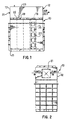
- Figure 1 is a front elevation of the odor control unit of the present invention;
- Figure 2 is a side elevation of the odor control unit shown in Figure 1;
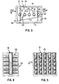
- Figure 3 is a plan view of the unit shown in Figure 1;
- Figure 4, 5 and 6 are diagrammatic views, front, side and top plan, of the matrix management of the canisters of the present invention;
- Figure 6a is a perspective illustration view of the matrix of canisters and standpipes;
- Figure 7 is a side elevation of a canister of the present invention;
- Figure 8 is a sectional elevation of the canister shown in Figure 7;
- Figure 9 is an end cap for the canister shown in Figure 7; and
- Figure 10 is a partial sectional elevation showing the canister shown in Figure 7 mounted in control unit shown in Figures 1-3.
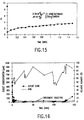
- Figures 11-18 are graphical presentations of the test results of housing the removal and restoration advantages of the invention.
-
- Referring to Figures 1 through 3, the
odor control unit 10 of the present invention comprises ahousing 11 preferably made of a plastic such as polypropylene or polyethylcne. Preferably, positioned on top ofhousing 11 is ahood unit 12 comprising anoutlet channel 13 and aninlet channel 14. As shown more clearly in Figure 3,inlet channel 14 provide convergingwalls end wall 18.Inlet channel 14 is in communication with a plurality ofstandpipes 19 andinlet port 21 is connected to a source of fumes or off gases driven to hood orcontrol unit 10 by means of blower (not shown) having a capacity of 4.733 m3s-1 (10000 cfm), for example, for use in municipal waste treatment system. Abase plate 22 andtop member 23 completes the sealing ofchannel 14. -
Outlet channel 13 utilizes convergingwalls canisters 25 shown more clearly in Figure 1. Outlet passageway is in communication with thehousing 11 containing a plurality of canisters arranged in a matrix as shown in Figures 4 through 6. Referring to Figures 4 through 6,canisters 25 are arranged in plurality of rows equal in number to the number ofstand pipes 19 arranged along the length ofhousing 11. As shown in Figure 4, each standpipe 19 has connected thereto five canisters on each side of the stand pipe. However, the exact number of canisters or standpipes is a matter of flow dynamics, removal ratios and rates and other parameters known for those skilled in the art for each appticaaon. The preferred embodiment, the matrix shown in Figures 4 - 6 is useful for almost all municipal waste odor control applications. As shown in Figures 5 and 6, eachcanister 25 is demountably attached as described hereinafter. - Referring to Figures 7 through 9, each
canister 25 preferably comprises acylindrical envelope 26 having a plurality ofperforations 27 for the passage of gas. In the presently preferred embodiment,envelope 26 comprises a flexible porous plastic matting made of 300 micron polyethylene particles which is heat pressure molded. Aninner conduit 28 which includesinlet port 29 is connected to standpipe 19pipe connector 36 for access to off gases containing hydrogen sulfide.Inner conduit 28 is preferably provided withgas inlet perforations 31 to permit gas to penetrate into theannulus 33 defined byenvelope 26 andinner conduit 28.Inner conduit 28 is also preferably made from the same material asenvelope 26.Annulus 33 preferably has a depth of 0.0762 to 0.1016m (3 to 4 inches) and most preferably 0.1016m (4 inches) for containing the carbonaceous char. End caps 34 and 35seal annulus 33. End caps 34 is removable to permit the filling and emptying of the nitrogen-treated carbonaceous char. A canister removal tool (not shown) is to be used by insertion throughinner conduit 28 to supportcanister 25 during attachment to standpipe 19 throughopening 37.Cylindrical envelope 26 andinner conduit 28 are preferably made from polyethylene. End caps 34 and 35 are also made from a plastic material such as polypropylene or polyethylene but can be made from other materials resistant to sulfuric acid. In the preferred embodiment,canister 25 has a length of 0.508m (20 inches) and an outer diameter of 0.2794m (11 inches) and 0.0762m (3 inches) inner diameter to provide a bed depth of 0.1016m (4"). Eachcanister 25 is designed to accommodate approximately 13.6 kg (30 pounds) of carbonaceous char. - The nitrogen treated carbonaceous char used in
canister 25 of the invention is prepared using a bituminous coal or materials having bituminous properties. The bituminous coal is pulverized, mixed with about 4 to 6% coal tar pitch, and briquetted. The resultant briquettes are crushed and sized to produce a mesh of 8 x 30 or 8 x 40 and preferably greater than 12 x 40 mesh (U.S. Standard Series sieves) material. In the presence of large quantities of excess air, this material is carbonized and oxidized at temperatures between about 250°C and 450°C for at least 3 hours. The resultant oxidized char is cooled to near ambient temperatures and subsequently impregnated with an aqueous urea solution or other nitrogen containing compound having at least one nitrogen-containing functionability in which the nitrogen exhibits a formal oxidation number less than that of elemental nitrogen and dried. The quantity of urea solution used was sufficient to produce a 2-4% urea loading on a dry weight basis. The impregnated, oxidized char is then heated to about 950°C in a furnace and maintained at that temperature for up to 1 hour. Immediately following this treatment the material is contacted with steam, while maintaining a 950°C temperature, for a period of time sufficient to achieve an Apparent Density (Test Method TM-7, Calgon Carbon Corporation, Pittsburgh, PA) of about 0.51 grams per cc for a 6x16 mesh (U.S. Standard Series sieves) particle size distribution. After gasification, the material is cooled to ambient temperature under an inert atmosphere. The nitrogen-treated carbon produced by this procedure is comparable in Apparent Density, adsorption properties, ash content, and iron content to BPL Carbon, a commercial unimpregnated vapor-phase activated carbon manufactured from the same feedstock. See U.S.Patent No.5,494,869 incorporated herein by reference. - As shown in Figure 10 each
canister 25 is mounted to an associatedstand pipe 19 by means ofconduit 36. Eachcanister 29 is preferably mounted through, and associatedopening 37 inhousing 11. The side wall closure 38 (Figure 6a and 10) is installed to ensurecanister 25 is held withincontrol unit 10. In the preferred method, rows of canisters can be exchanged on a scheduled basis after the carbon has been recycled to its limit.Preferred canister 25 are individually removed by detachment ofsidewall closure 38 and withdrawal throughopening 37, or removed as groups from thecontrol unit 10 matrix ofstandpipes 19 andhood unit 12.Water inlets 41 provide a source of regeneration water for cleaning rows of canisters. Water (H2SO4) is discharged throughoutlets 42. - Tests using a "centaur" carbon prepared as described above were conducted to determine the H2S removal levels and useful regeneration cycles of the invention. These tests used an airflow of 4.733 m3 s-1 (10,000 cfm) with an inflow H2S of 10 ppm at ambient temperatures. H2S breakthrough was set at 1.0 ppm. Figures 11 through 18 show the results of the test. In general, it was found that a 8x16 mesh carbon with a 0.1016 meter (four inch) bed depth contains a wave front at 0.7625 ms-1 (150 fpm). Regeneration using water at a countercurrent flow of about 1.174 ·10-3 - 1.761·10-3 kgs-1 m-3(2-3 gpm/ft3)
- The process of the present invention effectively uses the radial flow canister in parallel flow patterns to remove H2S laden fumes preferably pass through each
canister 25 at a rate of 0.7625 meter per second (150 feet per minute). Removal of the H2S is by adsorption into the carbon pores and catalytically converting it to H2SO4. The adsorption/reaction step is followed by a dynamic water washing at 3.33·10-5kg s-1 (2 g/m) or greater through each selected canister. The process advantageously permits recycling individual or groups of canisters by washing only a portion of the matrix moreover, by sequencing the recycle in a continuous manner, the carbon life can be generally extended. - While a presently preferred embodiment of the invention has been described in particularity, it may be otherwise embodied within the scope of the appended claims.
Claims (7)
- Apparatus for the removal of hydrogen sulfide comprising:(a) a housing (11), having an interior space and a fluid inlet (14) and outlet (13),(b) a plurality of fluid conduits (19) positioned within said housing (11), each in communication with said fluid inlet (14),(c) a plurality of canisters (25) arranged in a matrix of rows, each of said rows being associated with at least one fluid conduit (19), each of said canisters (25) comprising:(i) an envelope (26) having an inlet port (29) and outlet ports (27), each inlet port (29) being in communication with at least one fluid conduit (28) and said outlet ports (27) being in communication with said housing interior space, said envelope (26) and outlet ports (27) being comprised of a flexible porous molded particulate plastic material whereby fluid may pass therethrough;(ii) a nitrogen-treated carbonaceous char positioned in said canister (25) between said inlet (29) and outlet ports (27) of said canister (25).
- Apparatus as set forth in Claim 1 wherein said housing (11) is made of a plastic material resistant to sulfuric acid.
- Apparatus as set forth in Claim 1 wherein said housing (11) includes a hood (12), said hood (12) having a first portion in communication with said housing inlet (21) and each of said fluid conduits (19) and a second portion in communication with said housing interior space and said outlet (13).
- Apparatus as set forth in Claim 2 or 3 wherein said fluid conduits comprise standpipes (19).
- Apparatus as set forth in Claim 3 wherein said envelope (26) is cylindrical having ends and an inner conduit (28) spaced apart from said envelope (26) to define substantially an annular space (33) therebetween and an end wall (34,35) at the respective ends of said envelope (26) to define a chamber, said envelope (26) and inner conduit (28) providing communication therethrough to said chamber and said nitrogen-treated carbonaceous char being positioned therein, and said inner conduit (28) being in communication through said end wall (35) with at least one fluid conduit (19) and said envelope (26) being in communication with the interior space of said housing (11) through said outlet ports (27).
- Apparatus as set forth in Claim 5 wherein said inner conduit (28) is made from a plastic material resistant to sulfuric acid.
- Apparatus as set forth in Claim 6 wherein said inner conduit (28) is made from a flexible porous molded particulate plastic.
Applications Claiming Priority (3)
| Application Number | Priority Date | Filing Date | Title |
|---|---|---|---|
| US631070 | 1996-04-12 | ||
| US08/631,070 US5843381A (en) | 1996-04-12 | 1996-04-12 | Apparatus for removal of hydrogen sulfide |
| PCT/US1997/005880 WO1997038784A1 (en) | 1996-04-12 | 1997-04-09 | Apparatus and process for removal of hydrogen sulfide |
Publications (2)
| Publication Number | Publication Date |
|---|---|
| EP0894023A1 EP0894023A1 (en) | 1999-02-03 |
| EP0894023B1 true EP0894023B1 (en) | 2003-07-16 |
Family
ID=24529653
Family Applications (1)
| Application Number | Title | Priority Date | Filing Date |
|---|---|---|---|
| EP97917909A Expired - Lifetime EP0894023B1 (en) | 1996-04-12 | 1997-04-09 | Apparatus for removal of hydrogen sulfide |
Country Status (14)
| Country | Link |
|---|---|
| US (1) | US5843381A (en) |
| EP (1) | EP0894023B1 (en) |
| AT (1) | ATE245051T1 (en) |
| AU (1) | AU710676B2 (en) |
| BR (1) | BR9708560A (en) |
| CA (1) | CA2251565C (en) |
| DE (1) | DE69723551T2 (en) |
| DK (1) | DK0894023T3 (en) |
| ES (1) | ES2203795T3 (en) |
| IL (1) | IL126499A (en) |
| NZ (1) | NZ332277A (en) |
| PT (1) | PT894023E (en) |
| TR (1) | TR199802050T2 (en) |
| WO (1) | WO1997038784A1 (en) |
Families Citing this family (2)
| Publication number | Priority date | Publication date | Assignee | Title |
|---|---|---|---|---|
| GB2390266B (en) * | 2002-06-28 | 2005-12-21 | Samsung Electronics Co Ltd | Improvements in portable communication devices |
| US6805729B2 (en) * | 2002-10-29 | 2004-10-19 | H2Gen Innovations, Inc. | System and method for handling fluid using a manifold |
Family Cites Families (8)
| Publication number | Priority date | Publication date | Assignee | Title |
|---|---|---|---|---|
| US3847574A (en) * | 1973-03-14 | 1974-11-12 | American Air Filter Co | Charcoal filter arrangement |
| US3969095A (en) * | 1973-08-25 | 1976-07-13 | Shigeru Kurahashi | Air filter apparatus |
| US4411870A (en) * | 1981-12-28 | 1983-10-25 | Uop Inc. | Reactor system |
| CH668712A5 (en) * | 1985-10-08 | 1989-01-31 | Paul E Mueller | FILTER ARRANGEMENT IN A Coloring- EINBRENNKABINE. |
| US4778492A (en) * | 1987-02-19 | 1988-10-18 | Advanced Separation Technologies Incorporated | Continuous gas treatment method and apparatus for adsorption processes |
| US5071035A (en) * | 1989-02-28 | 1991-12-10 | Kiplinger Dale V | System for transferring fluid from a container to a remote location |
| FR2711323B1 (en) * | 1993-10-18 | 1996-06-21 | Inst Francais Du Petrole | Process for the removal by adsorption of hydrocarbons contained in the air. |
| US5494869A (en) * | 1994-03-29 | 1996-02-27 | Calgon Carbon Corporation | Process for regenerating nitrogen-treated carbonaceous chars used for hydrogen sulfide removal |
-
1996
- 1996-04-12 US US08/631,070 patent/US5843381A/en not_active Expired - Lifetime
-
1997
- 1997-04-09 CA CA002251565A patent/CA2251565C/en not_active Expired - Fee Related
- 1997-04-09 EP EP97917909A patent/EP0894023B1/en not_active Expired - Lifetime
- 1997-04-09 PT PT97917909T patent/PT894023E/en unknown
- 1997-04-09 WO PCT/US1997/005880 patent/WO1997038784A1/en not_active Ceased
- 1997-04-09 AT AT97917909T patent/ATE245051T1/en not_active IP Right Cessation
- 1997-04-09 DE DE69723551T patent/DE69723551T2/en not_active Expired - Fee Related
- 1997-04-09 ES ES97917909T patent/ES2203795T3/en not_active Expired - Lifetime
- 1997-04-09 BR BR9708560-0A patent/BR9708560A/en not_active IP Right Cessation
- 1997-04-09 TR TR1998/02050T patent/TR199802050T2/en unknown
- 1997-04-09 AU AU26103/97A patent/AU710676B2/en not_active Ceased
- 1997-04-09 DK DK97917909T patent/DK0894023T3/en active
- 1997-04-09 NZ NZ332277A patent/NZ332277A/en not_active IP Right Cessation
- 1997-04-09 IL IL12649997A patent/IL126499A/en not_active IP Right Cessation
Also Published As
| Publication number | Publication date |
|---|---|
| IL126499A0 (en) | 1999-08-17 |
| EP0894023A1 (en) | 1999-02-03 |
| BR9708560A (en) | 2000-01-04 |
| CA2251565C (en) | 2005-07-26 |
| US5843381A (en) | 1998-12-01 |
| DE69723551T2 (en) | 2004-06-09 |
| PT894023E (en) | 2003-11-28 |
| TR199802050T2 (en) | 2000-07-21 |
| WO1997038784A1 (en) | 1997-10-23 |
| AU2610397A (en) | 1997-11-07 |
| ATE245051T1 (en) | 2003-08-15 |
| IL126499A (en) | 2001-07-24 |
| DE69723551D1 (en) | 2003-08-21 |
| DK0894023T3 (en) | 2003-10-20 |
| CA2251565A1 (en) | 1997-10-23 |
| NZ332277A (en) | 2000-05-26 |
| ES2203795T3 (en) | 2004-04-16 |
| AU710676B2 (en) | 1999-09-30 |
Similar Documents
| Publication | Publication Date | Title |
|---|---|---|
| US5607496A (en) | Removal of mercury from a combustion gas stream and apparatus | |
| US5407647A (en) | Gas-scrubber apparatus for the chemical conversion of toxic gaseous compounds into non-hazardous inert solids | |
| TW321609B (en) | ||
| KR100252809B1 (en) | Filter dust collector for gaseous and particulate contaminants | |
| KR100264738B1 (en) | A method for removing air pollutant from flue gas continuously and an apparatus therefor | |
| US6079212A (en) | Gasification power generation process and gasification power generation equipment | |
| CN112638504A (en) | Selective catalytic reduction process and process for regenerating deactivated catalyst of process | |
| CN1102418C (en) | Regeneration method of waste gas adsorbing and treating system | |
| US5843381A (en) | Apparatus for removal of hydrogen sulfide | |
| JP3488632B2 (en) | Bag filter type dust collector and method for removing harmful gas using the dust collector | |
| CA2038953A1 (en) | Process for the removal or reduction of gaseous contaminants | |
| KR100476139B1 (en) | Hydrogen sulfide removal device and hydrogen sulfide removal capacity restoration method | |
| WO1992019365A1 (en) | Stack gas cleaning process | |
| CN215692850U (en) | Fluidized bed steam reforming tail gas treatment system | |
| MXPA98008414A (en) | Apparatus and process to remove sulfide from hidrog | |
| CN2507548Y (en) | Venturi and active carbon filter combined three-stage high-efficiency dusting purifying device | |
| JP2000093798A (en) | Organochlorine compound decomposition catalyst, its production method and exhaust gas treatment method | |
| JP4491696B2 (en) | Exhaust gas treatment equipment | |
| US3917799A (en) | Sulfur oxide adsorption and recovery | |
| JP3966485B2 (en) | Method and apparatus for treating exhaust gas generated during incineration of waste containing chlorine compounds | |
| JP3820027B2 (en) | Removal equipment for hydrogen chloride and sulfur dioxide | |
| Enneking | Control of carbon disulfide emissions from viscose processes | |
| KR102856039B1 (en) | Dry deodorization system for removing odors containing hydrogen sulfide | |
| CN221580233U (en) | SCR low emission device | |
| CA2179000C (en) | Removal of mercury from a combustion gas stream |
Legal Events
| Date | Code | Title | Description |
|---|---|---|---|
| PUAI | Public reference made under article 153(3) epc to a published international application that has entered the european phase |
Free format text: ORIGINAL CODE: 0009012 |
|
| 17P | Request for examination filed |
Effective date: 19981112 |
|
| AK | Designated contracting states |
Kind code of ref document: A1 Designated state(s): AT BE CH DE DK ES FI FR GB GR IE IT LI LU MC NL PT SE |
|
| 17Q | First examination report despatched |
Effective date: 19991222 |
|
| RTI1 | Title (correction) |
Free format text: APPARATUS FOR REMOVAL OF HYDROGEN SULFIDE |
|
| GRAH | Despatch of communication of intention to grant a patent |
Free format text: ORIGINAL CODE: EPIDOS IGRA |
|
| RTI1 | Title (correction) |
Free format text: APPARATUS FOR REMOVAL OF HYDROGEN SULFIDE |
|
| GRAH | Despatch of communication of intention to grant a patent |
Free format text: ORIGINAL CODE: EPIDOS IGRA |
|
| GRAA | (expected) grant |
Free format text: ORIGINAL CODE: 0009210 |
|
| AK | Designated contracting states |
Designated state(s): AT BE CH DE DK ES FI FR GB GR IE IT LI LU MC NL PT SE |
|
| PG25 | Lapsed in a contracting state [announced via postgrant information from national office to epo] |
Ref country code: LI Free format text: LAPSE BECAUSE OF FAILURE TO SUBMIT A TRANSLATION OF THE DESCRIPTION OR TO PAY THE FEE WITHIN THE PRESCRIBED TIME-LIMIT Effective date: 20030716 Ref country code: FI Free format text: LAPSE BECAUSE OF FAILURE TO SUBMIT A TRANSLATION OF THE DESCRIPTION OR TO PAY THE FEE WITHIN THE PRESCRIBED TIME-LIMIT Effective date: 20030716 Ref country code: CH Free format text: LAPSE BECAUSE OF FAILURE TO SUBMIT A TRANSLATION OF THE DESCRIPTION OR TO PAY THE FEE WITHIN THE PRESCRIBED TIME-LIMIT Effective date: 20030716 |
|
| REG | Reference to a national code |
Ref country code: GB Ref legal event code: FG4D |
|
| REG | Reference to a national code |
Ref country code: CH Ref legal event code: EP |
|
| REG | Reference to a national code |
Ref country code: IE Ref legal event code: FG4D |
|
| REF | Corresponds to: |
Ref document number: 69723551 Country of ref document: DE Date of ref document: 20030821 Kind code of ref document: P |
|
| REG | Reference to a national code |
Ref country code: GR Ref legal event code: EP Ref document number: 20030403604 Country of ref document: GR |
|
| PG25 | Lapsed in a contracting state [announced via postgrant information from national office to epo] |
Ref country code: SE Free format text: LAPSE BECAUSE OF FAILURE TO SUBMIT A TRANSLATION OF THE DESCRIPTION OR TO PAY THE FEE WITHIN THE PRESCRIBED TIME-LIMIT Effective date: 20031016 |
|
| REG | Reference to a national code |
Ref country code: CH Ref legal event code: PL |
|
| PG25 | Lapsed in a contracting state [announced via postgrant information from national office to epo] |
Ref country code: LU Free format text: LAPSE BECAUSE OF NON-PAYMENT OF DUE FEES Effective date: 20040409 |
|
| REG | Reference to a national code |
Ref country code: ES Ref legal event code: FG2A Ref document number: 2203795 Country of ref document: ES Kind code of ref document: T3 |
|
| PG25 | Lapsed in a contracting state [announced via postgrant information from national office to epo] |
Ref country code: MC Free format text: LAPSE BECAUSE OF NON-PAYMENT OF DUE FEES Effective date: 20040430 |
|
| ET | Fr: translation filed | ||
| PLBE | No opposition filed within time limit |
Free format text: ORIGINAL CODE: 0009261 |
|
| STAA | Information on the status of an ep patent application or granted ep patent |
Free format text: STATUS: NO OPPOSITION FILED WITHIN TIME LIMIT |
|
| 26N | No opposition filed |
Effective date: 20040419 |
|
| PGFP | Annual fee paid to national office [announced via postgrant information from national office to epo] |
Ref country code: PT Payment date: 20060407 Year of fee payment: 10 |
|
| PGFP | Annual fee paid to national office [announced via postgrant information from national office to epo] |
Ref country code: GB Payment date: 20060412 Year of fee payment: 10 |
|
| PGFP | Annual fee paid to national office [announced via postgrant information from national office to epo] |
Ref country code: BE Payment date: 20060413 Year of fee payment: 10 |
|
| PGFP | Annual fee paid to national office [announced via postgrant information from national office to epo] |
Ref country code: IE Payment date: 20060418 Year of fee payment: 10 Ref country code: FR Payment date: 20060418 Year of fee payment: 10 |
|
| PGFP | Annual fee paid to national office [announced via postgrant information from national office to epo] |
Ref country code: DK Payment date: 20060420 Year of fee payment: 10 |
|
| PGFP | Annual fee paid to national office [announced via postgrant information from national office to epo] |
Ref country code: DE Payment date: 20060427 Year of fee payment: 10 Ref country code: AT Payment date: 20060427 Year of fee payment: 10 |
|
| PGFP | Annual fee paid to national office [announced via postgrant information from national office to epo] |
Ref country code: NL Payment date: 20060428 Year of fee payment: 10 Ref country code: GR Payment date: 20060428 Year of fee payment: 10 |
|
| PGFP | Annual fee paid to national office [announced via postgrant information from national office to epo] |
Ref country code: IT Payment date: 20060430 Year of fee payment: 10 |
|
| PGFP | Annual fee paid to national office [announced via postgrant information from national office to epo] |
Ref country code: ES Payment date: 20060503 Year of fee payment: 10 |
|
| REG | Reference to a national code |
Ref country code: PT Ref legal event code: MM4A Free format text: LAPSE DUE TO NON-PAYMENT OF FEES Effective date: 20071009 |
|
| REG | Reference to a national code |
Ref country code: DK Ref legal event code: EBP |
|
| GBPC | Gb: european patent ceased through non-payment of renewal fee |
Effective date: 20070409 |
|
| BERE | Be: lapsed |
Owner name: *CALGON CARBON CORP. Effective date: 20070430 |
|
| NLV4 | Nl: lapsed or anulled due to non-payment of the annual fee |
Effective date: 20071101 |
|
| PG25 | Lapsed in a contracting state [announced via postgrant information from national office to epo] |
Ref country code: PT Free format text: LAPSE BECAUSE OF NON-PAYMENT OF DUE FEES Effective date: 20071009 Ref country code: NL Free format text: LAPSE BECAUSE OF NON-PAYMENT OF DUE FEES Effective date: 20071101 Ref country code: DE Free format text: LAPSE BECAUSE OF NON-PAYMENT OF DUE FEES Effective date: 20071101 |
|
| REG | Reference to a national code |
Ref country code: IE Ref legal event code: MM4A |
|
| PG25 | Lapsed in a contracting state [announced via postgrant information from national office to epo] |
Ref country code: AT Free format text: LAPSE BECAUSE OF NON-PAYMENT OF DUE FEES Effective date: 20070409 |
|
| PG25 | Lapsed in a contracting state [announced via postgrant information from national office to epo] |
Ref country code: BE Free format text: LAPSE BECAUSE OF NON-PAYMENT OF DUE FEES Effective date: 20070430 |
|
| PG25 | Lapsed in a contracting state [announced via postgrant information from national office to epo] |
Ref country code: GB Free format text: LAPSE BECAUSE OF NON-PAYMENT OF DUE FEES Effective date: 20070409 Ref country code: DK Free format text: LAPSE BECAUSE OF NON-PAYMENT OF DUE FEES Effective date: 20070430 |
|
| PG25 | Lapsed in a contracting state [announced via postgrant information from national office to epo] |
Ref country code: IE Free format text: LAPSE BECAUSE OF NON-PAYMENT OF DUE FEES Effective date: 20070409 |
|
| REG | Reference to a national code |
Ref country code: ES Ref legal event code: FD2A Effective date: 20070410 |
|
| PG25 | Lapsed in a contracting state [announced via postgrant information from national office to epo] |
Ref country code: FR Free format text: LAPSE BECAUSE OF NON-PAYMENT OF DUE FEES Effective date: 20070430 |
|
| PG25 | Lapsed in a contracting state [announced via postgrant information from national office to epo] |
Ref country code: GR Free format text: LAPSE BECAUSE OF NON-PAYMENT OF DUE FEES Effective date: 20071102 Ref country code: ES Free format text: LAPSE BECAUSE OF NON-PAYMENT OF DUE FEES Effective date: 20070410 |
|
| PG25 | Lapsed in a contracting state [announced via postgrant information from national office to epo] |
Ref country code: IT Free format text: LAPSE BECAUSE OF NON-PAYMENT OF DUE FEES Effective date: 20070409 |