This invention relates to an apparatus and method for coding a video
signal derived from a motion picture film source in which the video signal
includes duplicate pictures, and includes frames consisting of fields
originating from different frames of the motion picture film source.
The Motion Picture Experts Group (MPEG) standard is representative
of a standard for compressing digital video signals for transmission or
storage. The standard was discussed by ISO-IEC/JTC1/SC2/WG11 and has
been proposed as a draft standard. The standard stipulates a hybrid
compression method, combining motion compensated prediction coding with
discrete cosine transform (DCT) coding.
The first compression technique, motion compensated prediction coding,
takes advantage of the correlation of video signals in the time domain.
According to this method, the video signal representing the current picture (a
frame or a field) is predicted from the decoded and reproduced
(reconstituted) video signal representing a reference picture, which is a
picture that is earlier or later than the current picture. Only the motion
prediction errors between the video signal representing the current picture
and the reconstituted video signal representing the reference picture are
transmitted or stored. This significantly reduces the amount of digital video
signal required to represent the current picture.
The second compression technique, DCT coding, takes advantage of the
intra-picture, two-dimensional correlation of a video signal. According to
this technique, when a block of the current picture, or a block of motion
prediction errors, is orthogonally transformed, signal power is concentrated
in specific frequency components. Consequently, quantizing bits need only
be allocated to the DCT coefficients in the region in which the signal power
is concentrated. This further reduces the quantity of digital video signal
required to represent the picture. For example, in a region in which the
image has little detail, and in which the video signal is thus highly
correlated, the DCT coefficients are concentrated at low frequencies. In that
case, only the DCT coefficients in the low-frequency region of the
distribution pattern are quantized to reduce the quantity of the digital video
signal.
Because the coding techniques of the MPEG standard are basically
intended for use with interlaced video signals, problems arise when they are
applied without modification to progressive (non-interlaced) video signals.
In particular, the compression ratio can be impaired when the MPEG
techniques are applied to progressive video signals.
A motion picture consists of a sequence of still pictures reproduced in
succession, normally 24 pictures per second. A motion picture film source,
e.g., a motion picture film or a 24-frame video signal, represents each
picture of the motion picture as a full frame with a frame rate of 24 Hz,
whereas an interlaced video signal represents each picture of the motion
picture as two consecutive fields, each field representing half of the picture
and being displaced from one the other by one line. An NTSC interlaced
video signal has a field rate of 60 Hz. Consequently, deriving an interlaced
video signal with a field rate of 60 Hz from a motion picture film source
with a frame rate of 24 Hz, such as is done by a telecine machine, requires a
conversion between the number of frames per second of the film source and
the number of fields per second in the video signal.
A motion picture film source with a 24 Hz frame rate is commonly
converted to an interlaced video signal with a 60 Hz field rate, such as an
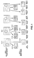
NTSC video signal, by a technique known as 2-3 pull-down. Figure 1
illustrates how 2-3 pull-down works.
The 2-3 pull-down process involves a repetitive sequence of deriving
two fields of the video signal from the first of every two consecutive frames
of the motion picture film source, and deriving three fields of the video
signal from the second of the two consecutive frames of the film source. In
Figure 1, frames 1500 and 1501 are consecutive frames of a motion picture
film source with a frame rate of 24 Hz. In the figure, each film source
frame is divided into an odd field, indicated by a solid line, and an even
field, indicated by a broken line.
First, two fields of the video signal are derived from the first film
source frame 1500. The video field 1502, an odd field, is first derived from
the first film source frame 1500, followed by the second video field 1503, an
even field. Then, three fields of the video signal are derived from the
second film source frame 1501. The video field 1504, an odd field, is first
derived, followed by the video field 1505, an even field, followed by the
video field 1506, another odd field. The two odd fields 1504 and 1506 are
identical to one another. This process is repeated for the other two film
source frames 1508 and 1509 from which the video fields 1510 through 1514
are derived. Note that an even field 1510 is derived first from the film
source frame 1508, and that two even fields 1512 and 1514 are derived from
the film source frame 1509. With the arrangement shown, a sequence of ten
fields of the video signal is derived from a sequence of four frames of the
motion picture film source, after which the sequence is repeated.
Figure 2 shows the result of combining into frames consecutive pairs of
fields of the interlaced video signal derived by the process shown in
Figure 1. The video fields 1600 and 1601 are derived from the same film
source frame. Video fields 1602 and 1603 are also derived from the same
film source frame. Hence, the video frame 1607, produced by combining
the video fields 1600 and 1601, and the video frame 1608, produced by
combining the video fields 1602 and 1603, are each derived from the same
film source frame. On the other hand, the video frame 1609, produced by
combining the consecutive video fields 1604 and 1605 is derived from two
different film source frames.
When MPEG coding is applied to the frames of a non-interlaced
video signal derived from an interlaced video signal, which, in turn, is
derived from a motion picture film source using 2-3 pulldown, coding the frames
1607 and 1608 in the above example presents no problems because these
frames are each derived from a single film source frame, and are thus
internally correlated. However, difficulties can be encountered when coding
the video frame 1609 because it is derived from two different frames of the
film source, and, hence, it is not necessarily internally correlated.
If the motion picture is fast-moving, or if a scene change occurs within
the frame, a video frame derived from two different frames of the film
source has low vertical correlation, which reduces the efficiency of
DCT-based signal compression. Moreover, motion compensated prediction
can also go wrong because of the reduced correlation of the video signal.
Accordingly, a first aspect of the invention provides a method for coding an
input video signal to provide a coded signal. The input video signal has a field
rate of 60 Hz and is derived from a motion picture film source using 2-3
pulldown. In the method, first frames, consisting of fields derived from
different frames of the motion picture film source, are detected in the input
video signal. Then, the input video signal is predictively coded to provide
the coded signal by using second frames as reference pictures. Second
frames are frames of the input video signal other than the first frames
detected in the detecting step.
The method may detect the first frames by detecting duplicate fields
in the input video signal, the method may additionally eliminate the duplicate
fields from the input video signal, and include in the coded signal a skip-picture
flag in lieu of each eliminated duplicate field, and a reference picture
code identifying a field to be copied to provide each eliminated duplicated
field.
A second aspect of the invention provides a method for coding an input
video signal to provide a coded signal, in which duplicate pictures are detected
in the input video signal, and each duplicate picture is eliminated from the
input video signal to provide an encoder input signal. The encoder input
signal is predictively coded using plural predictive coding methods to
provide the coded signal. Finally, a skip-picture flag is included in the
coded signal in lieu of each eliminated duplicate picture, and a reference
picture code identifying a field to be copied to provide each eliminated
duplicate picture is also included in the coded signal.
A third aspect of the invention provides a method for decoding a coded
signal to provide an output video signal, in which the coded signal is derived by
applying predictive coding to an input video signal having a field rate of
60 Hz and being derived from a motion picture film source using 2-3 pull-down.
The predictive coding is applied such that frames of the input video
signal consisting of fields derived from different frames of the motion picture
source are coded using field mode coding, and all other frames of the input
video signal are coded using frame mode coding. The coded video signal
includes a processing mode flag signal indicating a coding mode for each
frame. In the method, the processing mode flag for each frame is extracted
from the coded signal, and inverse predictive coding is applied to the coded
signal to provide the output video signal. The inverse predictive coding for
each frame has the coding mode indicated by the processing mode flag
extracted from the coded signal.
A fourth aspect of the present invention provides a method for decoding a
coded signal to provide an output video signal. The coded signal is
generated by eliminating duplicate pictures from an input video signal. The
coded signal includes, in lieu of each eliminated duplicate picture, a skip-picture
flag, and a reference picture code identifying a picture to be copied
to provide the eliminated duplicate picture. In the method, the skip picture
flag and the reference picture code are extracted from the coded video
signal. Inverse predictive coding is applied to the coded signal to provide
the output video signal. Finally, the picture indicated by the reference
picture code is copied in response to the skip picture flag to restore an
eliminated duplicate picture to the output video signal.
A fifth aspect of the invention provides a recording, comprising a recording
medium and a recording signal recorded in the recording medium. The
recording signal includes a video input signal derived from a motion picture
film source and coded by predictive coding using as reference pictures only
frames of the input video signal that consist of fields derived from the same
frame of the motion picture source.
A sixth aspect of the invention provides a recording, comprising a
recording medium; and a recording signal recorded in the recording medium,
wherein the recording signal includes a coded video input signal wherefrom
duplicate pictures are eliminated, and also includes in lieu of each eliminated
duplicate picture, a skip picture flag and a picture reference code identifying
a field to be copied to restore the eliminated duplicate picture.
A seventh aspect of the invention provides an apparatus for coding an
input video signal to provide a coded signal. The input video signal has a field
rate of 60 Hz and is derived from a motion picture film source using 2-3
pulldown. The apparatus comprises a circuit that detects first frames in the
input video signal. First frames consist of fields derived from different
frames of the motion picture film source. The apparatus also comprises a
predictive coding circuit that provides the coded signal by predictively
coding the input video signal. The predictive coding circuit uses second
frames as reference pictures. Second frames are frames of the input video
signal other than the first frames detected by the detecting circuit.
An eighth aspect of the invention provides an apparatus for coding an
input video signal to provide a coded signal comprises a detecting circuit that
detects duplicate pictures in the input video signal. A circuit eliminates each
detected duplicate picture from the input video signal to provide an encoder
input signal. A predictive coding circuit predictively codes the encoder input
signal using plural predictive coding methods to provide the coded signal.
Finally, a circuit includes a skip-picture flag in the coded signal in lieu of
each eliminated duplicate picture, and additionally includes in the coded
signal a reference picture code identifying a field to be copied to provide
each eliminated duplicate picture.
A ninth aspect of the invention provides an apparatus for decoding a
coded signal to provide an output video signal. The coded signal is derived by
applying predictive coding to an input video signal having a field rate of
60 Hz. The input video signal is derived from a motion picture film source
by 2-3 pull-down. The predictive coding is applied such that frames of the
input video signal consisting of fields derived from different frames of the
motion picture source are coded using field mode coding, and all other
frames of the input video signal are coded using frame mode coding. The
coded video signal includes a processing mode flag signal indicating a coding
mode for each frame. The apparatus comprises an extracting circuit that
extracts the processing mode flag for each frame from the coded signal. The
apparatus additionally comprises a circuit that applies inverse predictive
coding to the coded signal to provide the output video signal. The inverse
predictive coding applied to each frame has the coding mode indicated by the
processing mode flag extracted by the extracting circuit.
A tenth aspect of the invention provides a decoding apparatus for
decoding a coded signal to provide an output video signal. The coded signal
is generated by eliminating duplicate pictures from an input video signal, and
includes a skip-picture flag in lieu of each eliminated duplicate picture, and a
reference picture code identifying a field to be copied to provide the
eliminated duplicate picture. The decoding apparatus comprises a circuit that
extracts the skip picture flag and the reference picture code from the coded
signal and a circuit that applies inverse predictive coding to the coded signal
to provide the output video signal. The apparatus additionally comprises a
circuit that copies, in response to the skip picture flag, the picture indicated
by the reference picture code to restore an eliminated duplicate field to the
output video signal.
An eleventh aspect of the invention provides a system for deriving a
recording signal from an input video signal and for reproducing the recorded signal
to provide an output video signal. The recording signal has a bit rate substantially
lower than the input video signal and the output video signal. The input video
signal and the output video signal have a field rate of 60 Hz, and the input video
signal is derived from a motion picture film using 2-3 pulldown. The system
comprise an encoding apparatus and a decoding apparatus. The encoding apparatus
comprises a circuit that detects first frames in the input video signal. First frames
consist of fields derived from different frames of the motion picture film source.
The encoding also includes a predictive coding circuit that predictively codes the
video input signal to
provide the recording signal. The predictive coding circuit codes each first
frame using field mode coding and codes each second frame using frame
mode coding. A second frame is a frame of the input video signal other
than a first frame detected by the detecting circuit. Finally the encoding
apparatus comprises a circuit that includes in the recording signal a
processing mode flag indicating a coding mode for each frame of the input
video signal. The decoding apparatus comprises a circuit that extracts the
processing mode flag for each frame from the recording signal. The
decoding apparatus also includes a circuit that applies inverse predictive
coding to the recording signal to provide the output video signal. The
inverse predictive coding applied to each frame has the coding mode
indicated by the processing mode flag extracted by the extracting circuit.
A twelfth aspect of the invention provides a system for deriving a recording
signal from an input video signal and for reproducing the recorded signal to
provide an output video signal. The recording signal has a bit rate substantially
lower than the input video signal and the output video signal. The system
comprises an encoding apparatus and a decoding apparatus. The encoding
apparatus comprises a circuit that detects duplicate pictures in the input video
signal and a circuit that eliminates each duplicate picture from the input video
signal. A predictive coding circuit predictively codes the encoder input signal
using plural predictive coding methods to provide the recording signal. The
encoding apparatus additionally comprises a circuit that includes a skip-picture
flag in the recording signal in lieu of each eliminated duplicate picture, and that
additionally includes in the recording signal a reference picture code identifying a
field to be copied to provide each eliminated duplicate picture. The decoding
apparatus comprises a circuit that extracts the skip picture flag and the reference
picture code from the recording signal, and a
circuit that applies inverse predictive coding to the recording signal to
provide the output video signal. Finally, the decoding apparatus comprises a
circuit that copies, in response to the skip picture flag, the picture indicated
by the reference picture code to restore an eliminated duplicate field to the
output video signal.
Specific embodiments of the invention will now be described, by way of
example, with reference to the accompanying drawings, in which:
Figure 1 illustrates the principle of the 2-3 pulldown.
Figure 2 illustrates how the coding efficiency is reduced in a frame
derived by 2-3 pulldown from different motion picture film source frames.
Figure 3 is a block diagram showing the coding apparatus and the
decoding apparatus in a first embodiment of the present invention.
Figure 4 is a block diagram showing the construction of the 2-3
pulldown detection circuit of an embodiment of encoding apparatus according
to the present invention
Figure 5 illustrates the timing of the duplication detection signal in
the 2-3 pulldown detection circuit.
Figure 6 is a block diagram of the processing mode selection circuit
in an embodiment of coding apparatus according to the present invention.
Figure 7 illustrates the timing of the signals generated by the
processing mode selection circuit in the coding apparatus.
Figure 8 illustrates prediction.
Figure 9 is a block diagram showing the field sequence exchanging
circuit in the coding apparatus.
Figure 10 illustrates the scan conversion operation of the present
embodiment.
Figure 11 illustrates frame formation.
Figure 12 is a block diagram showing the encoder of the coding
apparatus according to the first embodiment of the present invention.
Figure 13 illustrates motion prediction mode selection in the encoder.
Figure 14 is a block diagram showing decoder in the decoding
apparatus according to the first embodiment of the invention.
Figure 15 illustrates duplication of a skip picture when the skip
picture is a P-picture in the decoder of the decoding apparatus.
Figure 16 illustrates duplication of a skip picture when the skip
picture is a B-picture in the decoder of the decoding device.
Figure 17 is a block diagram showing the coding apparatus and the
decoding apparatus according to a second embodiment of the present
invention.
Figure 18 is a block diagram showing the processing mode selecting
circuit of the coding apparatus according to the second embodiment of the
invention.
Figure 19 is a block diagram showing the field order exchange and
scan converting circuit of the coding apparatus according to the second
embodiment of the invention.
Figure 20 is a block diagram showing the encoder in the coding
apparatus according to the second embodiment of the invention.
Figure 21 is a block diagram illustrating the field order exchange and
scan converting circuit of the decoding device according to the second
embodiment of the invention.
Figure 22 is a block circuit diagram showing the arrangement of a
third embodiment of the coding apparatus according to the invention in
which coding is carried out in two passes.
Figure 3 shows the coding apparatus 100 and the decoding apparatus
101 that form the video signal processing apparatus according to the first
embodiment of the present invention. The coding apparatus 100 embodying
the first aspect of the present invention includes the 2-3 pull-down detection
circuit 102 for detecting duplicate fields in the coder input signal VI, a video
signal having a field rate of 60 Hz that is derived from a motion picture film
source by 2-3 pull-down. The 2-3 pull-down detection circuit 102 generates
the duplication detection signal DDS, and delays the coder input signal VI by
a predetermined processing time to generate the video signal VI1.
The coding apparatus 101 also includes the processing
mode selecting
circuit 103 which generates, in response to the duplication detection signal
DDS, the overflow signal OVF from the variable-
length coder 106, and the
video signal VI1, the following control signals and flags for each picture in
the coder input signal VI:
The processing mode selecting circuit 103 additionally delays the
video signal VI1 by a predetermined processing time to generate the video
signal VI2.
The coding apparatus 100 also includes the scan converter 104 that
converts two interlaced fields of the video signal VI2 into a progressive
frame when the processing unit flag PUC indicates that the picture is to be
coded using frame mode coding. Otherwise, when the processing unit flag
PUC indicates that the picture is to be coded using field mode coding, the
scan converter 104 supplies the two fields of the video signal VI2
unmodified as two fields of the video signal VI3.
The field sequence exchange circuit 105 receives the video signal VI3
and changes the picture sequence of the video signal VI3 to the sequence
required by the encoder 106 in response to the skip picture flag SPC, the
processing unit flag PUC, the prediction mode code PMC, and the reference
picture code RFC generated by the processing mode selecting circuit 103.
The field sequence exchange circuit 105 provides the resulting sequence-exchanged
video signal as the video signal VI4.
The encoder 106 codes the video signal VI4 in response to the skip
picture flag SPC, the prediction mode code PMC, and the reference picture
code RFC generated by the processing mode selecting circuit 103, to
generate the coded signal VC1. The error correction coding (ECC) circuit
107 appends error correction codes to the encoded signal VC1 to generate
the encoded signal VC2, which passes to the modulating circuit 108 where it
is modulated to provide the recording signal VC3 for recording on the
recording medium 109.
The decoding apparatus 101 of the first embodiment of the invention
includes the demodulating circuit 111 for demodulating the signal VD1
reproduced from the recording medium 110 to provide the decoded signal
VD2. The recording medium 110 is the same as, or is derived from, the
recording medium 109. The decoded signal VD2 passes to the error
correction code decoder (ECC decoder) 112, which detects and corrects
errors in the decoded signal VD2 to provide the decoder input signal VD3.
The decoder 113 extracts from the decoder input signal VD3 the skip picture
flag SPC, the processing unit flag PUC, the prediction mode code PMC, and
the reference picture code RFC that were generated by the processing mode
selecting circuit 103, and provides these flags and codes as the skip picture
flag SPD, the processing unit flag PUD, the prediction mode code PMD,
and the reference picture code RFD, respectively. The decoder 113 also
decodes the coded picture signals in the decoder input signal VD3 in
response to these flags and codes to provide the decoder output signal VO1.
The scan converting circuit 114 converts one frame of the decoder
output signal VO1 into two fields of the video signal VO2 when the
processing unit flag PUD from the decoder 113 indicates that the frame was
processed in frame mode. Otherwise, when the processing unit flag PUD
from the decoder 113 indicates that the frame was processed in field mode,
the scan converting circuit 114 supplies the video signal VO1 unmodified as
two fields of the video signal VO2.
The sequence exchange circuit 115 restores the picture sequence of
the video signal VO2 to the picture sequence of the coder input signal VI to
provide the decoder apparatus output signal VO. The sequence exchange
circuit 115 changes the picture sequence in response to the skip picture flag
SPD, the processing unit flag PUD, the prediction mode code PMD, and the
reference picture code RFD from the decoder 113. The resulting decoding
apparatus output signal VO is a video signal that is suitable for display on a
monitor after conversion to an analog signal.
The coding apparatus 100 according to the first embodiment of the
invention will now be described in detail. The coder input signal VI, a
video signal with a 60 Hz field rate, is fed into the 2-3 pull-down detection
circuit 102. The 2-3 pulldown detection circuit 102 detects each duplicate
field in the coder input signal VI, and generates the duplication detection
signal DDS in response thereto. The 2-3 pull-down detection circuit 102
also delays the coder input signal VI by a time corresponding to the
processing delay of the 2-3 pulldown detection circuit before feeding the
delayed coder input signal VI out as the video signal VI1.
The processing
mode selecting circuit 103 derives four signals for
each picture in the video signal VI1 in response to the video signal VI1 and
the duplication detection signal DDS. These signals are:
The processing mode selecting circuit 103 delays the video signal VI1
by a time equal to the processing time of the processing mode selecting
circuit before feeding the video signal VI1 out as the video signal VI2.
If the processing unit flag PUC generated by the processing mode
selection circuit 103 indicates that a picture will be coded in frame mode, the
scan converting circuit 104 interleaves the two fields of the field-based video
signal VI2 into a single frame, which it feeds out as a picture of the video
signal VI3. If the processing unit flag PUC indicates that a picture will be
coded in field mode, the processing mode selection circuit feeds the two
fields of the video signal VI2 out unchanged as two fields of the video signal
VI3. The sequence exchange circuit 105 changes the picture (field or
frame) sequence of the video signal VI3 to provide the encoder input signal
VI4 with the picture sequence required by the encoder 106. The sequence
exchange circuit changes the picture sequence in response to the skip picture
flag SPC, the processing unit flag PUC, the prediction mode code PMC, and
the reference picture code RFC.
The encoder 106 encodes the encoder input signal VI4 in response to
the skip picture flag SPC, the processing unit flag PUC, the prediction mode
code PMC, and the reference picture code RFC, received from the
processing mode selecting circuit 103, and provides the encoder output signal
VC1.
The ECC circuit 107 appends error correction codes to the encoder
output signal VC1 to provide the encoded signal VC2, which the modulating
circuit 108 modulates to provide the recording signal VC3 for recording by a
recording apparatus, not shown, on the recording medium 109.
The decoding apparatus 101 will now be described in detail. The
recording signal VD1, read out from the recording medium 110, is
demodulated by the demodulating circuit 111 to provide the demodulated
signal VD2. The ECC decoding circuit 112 applies error detection and
correction to the demodulated signal VD2 to generate the decoder input
signal VD3.
The decoder input signal VD3 is fed into the decoder 113, which
extracts from the signal VD3 the skip picture flag SPC, the processing unit
flag PUC, the prediction mode code PMC, and the reference picture code
RFC that were generated by the processing mode selecting circuit 103, and
provides them as the skip picture flag SPD, the processing unit flag PUD,
the prediction mode code PMD, and the reference picture code RFD. The
decoder 113 also decodes the coded picture signals in the decoder input
signal VD3 to provide the decoder output signal VO1.
The scan converting circuit 114 converts one frame of the video
signal VO1 into two fields of the video signal VO2 when the processing unit
flag PUD from the decoder 113 indicates that the frame was processed in
frame mode. Otherwise, the scan converting circuit 114 supplies two fields
of the video signal VO1 without modification as two fields of the video
signal VO2.
The sequence exchange circuit 115 restores the picture sequence of
the video signal VO2 to the picture sequence of the coder input signal VI to
provide the decoder apparatus output signal VO. The sequence exchange
circuit 115 changes the picture sequence in response to the skip picture flag
SPD, the processing unit flag PUD, prediction mode code PMD, and the
reference picture code RFD from the decoder 113. This permits the
recording signal to be reproduced from the recording medium 110.
The coding apparatus 100 will now be described in more detail.
Operation of the 2-3 pulldown detection circuit 102 will be described first
with reference to Figures 4 and 5. In Figure 4, the coder input signal VI, a
video signal with a field rate of 60 Hz, is fed into the selector 207 which
extracts the even fields from the coder input signal to provide the video
signal VP2. The video signal VP2 is fed into the subtractor 203. The coder
input signal VI is delayed by two field periods by the field delay circuits 201
and 202 and is also fed to the subtractor 203. The subtractor 203 calculates
a pixel-by-pixel difference between the coder input signal delayed by two
fields VP1, and the video signal VP2 from the selector 207, and feeds the
resulting difference signal VP3 to the absolute value circuit 204.
The absolute value circuit 204 determines the absolute value of each
difference value in the difference signal VP3, and passes the result as the
signal VP4 to the accumulator 205, which calculates the sum of the absolute
values of the differences for each field, and passes the resulting difference
absolute value sum for each field VP5 to the comparator 206.
The comparator 206 compares the value of the difference absolute
value sum for each field VP5 to a threshold value TH. If the comparator
206 determines that the difference absolute value sum is less than the
threshold value TH, the comparator generates the duplication detection signal
DDS to indicate that the field of the coder input signal VI is a duplicate
field.
Figure 5 illustrates the way in which the 2-3 pull-down detection
circuit 102 generates the duplication detection signal DDS. In Figure 5, the
coder input signal VI, a video signal with a 60 Hz field rate, is derived from
the frames of a motion film source using 2-3 pull down. The odd field 0
and the even field 1 of the coder input signal VI are both derived from the
film source frame A, whereas the odd fields 2 and 4 and the even field 3 of
the coder input signal VI are all derived from the film source frame B. The
even field 5 and the odd field 6 of the coder input signal VI are both derived
from the film source frame C, whereas the even fields 7 and 9 and the odd
field 8 of the coder input signal VI are all derived from the film source
frame D.
Figure 5 also shows the timing of the video signal VP1 delayed by
two fields relative to the coder input signal VI, and the video signal VP2
consisting of only the even fields of the coder input signal VI as they are
supplied to the subtractor 203. As a result, the subtractor 203 only
generates differences for even fields. When field 2 of the coder input signal
enters the subtractor 203 via the delayed video signal VP1 and field 4 of the
coder input signal simultaneously enters the subtractor 203 via the video
signal VP2, the differences calculated by the subtractor will be small because
field 2 and field 4 of the coder input signal originate from the same film
source frame. Consequently, the difference absolute value sum VP5 from
the accumulator 205 will be less than the threshold value TH, and the
comparator 206 will generate the duplication detection signal DDS.
The 2-3 pull-down detection circuit 102 additionally feeds the video
signal VI1, which is delayed by one field period relative to the coder input
signal VI, to the processing mode selection circuit 103.
Operation of the processing selection circuit 103 will now be
described with reference to Figures 6 through 8. Figure 6 shows the
arrangement of the processing mode selection circuit 103 in which the video
signal VI1 is supplied to the delay circuit 401. The delay circuit 401 delays
the video signal VI1 by different multiples of a field period and feeds
multiple delayed signals out as the video signal VS1. Additionally, the delay
circuit 401 delays the video signal VI1 by the processing time required by
the processing mode selection circuit 103 and supplies the delayed video
signal VI1 as the video signal VI2 to the scan conversion circuit 104.
In the processing mode selection circuit 103, the redundancy
detection circuit 402 detects duplicate pictures (field or frame) in the video
signal VI1 by comparing the current picture with various other pictures in
the video signal VS1. A duplicate picture is a picture that exhibits little or
no change relative to another picture. The processing mode selection circuit
103 generates the skip picture flag SPC in response to detected duplicate
pictures. Additionally, the processing mode selection circuit 103 generates
the skip picture flag SPC in response to duplicate pictures indicated by the
duplication detection signal DDS.
Figure 7 illustrates the timing of the skip picture flag SPC when a
duplicate field is detected. In Figure 7, fields 0 through 9 of the video
signal VI1, which has a field rate of 60 Hz, are derived from frames A
through D of a motion picture film source, as described above with reference
to Figure 5. The fields of the video signal VI1 are then formed into frames
as follows: the frame F0 is made up of fields 0 and 1, the frame F1 is made
up of fields 2 and 3, the frame F2 is made up of fields 4 and 5, the frame
F3 is made up of fields 6 and 7, and the frame F4 is made up of fields 8 and
9.
In the example shown, the redundancy detection circuit 402 generates
the skip picture flag SPC for field 4, a duplicate field indicated by the
duplicate detection signal DDS, and for field 7, a duplicate field that
duplicates field 9, and which is detected by the redundancy detection circuit
402. The skip picture flag for field 4 is generated in response to the
duplication detection signal DDS.
The processing mode selection circuit 103 also generates the skip
picture flag SPC when it receives the overflow flag OVF from the encoder
106. The overflow flag will be described further below. This is achieved
by the OR gate 405, which performs an OR operation between the output of
the redundancy detection circuit 402 and the overflow flag OVF. As
mentioned above, the redundancy detection circuit 402 also generates the
skip picture flag SPC if a picture is designated as a skip picture by the
duplicate detection signal DDS. The encoder 106 includes the skip picture
flag SPC and the reference picture code RFC in the coding apparatus output
signal VC1 in lieu of each duplicate picture, as will be described below.
Returning to Figure 6, the processing unit decision circuit 403
generates the processing unit flag PUC in response to the delayed video
signal VS1 from the delay circuit 401, and in response to the skip picture
code SPC from the redundancy detection circuit 402. In the example shown
in Figure 7, the processing unit flag PUC indicates that frames F2 and F3
are to be coded in field mode since each field in the frames F2 and F3 is
derived from a different film source frame. The processing unit flag PUC
indicates that the other frames F0, F1, and F4 are to be coded in frame
mode.
The prediction mode decision circuit 404 generates the prediction
mode code PMC indicating the prediction mode of each picture, and, in
response to the skip picture flag, generates the reference picture signal RFC
indicating the picture that will be used as the reference picture for
reproducing the skip picture.
Prediction mode will now be explained with reference to Figure 8. In
Figure 8, the frame B2, made up of fields b20 and b21, and the frame B3,
made up of fields b30 and b31, each include fields derived from different
film source frames, as described above. Therefore, the prediction mode
decision circuit 404 sets the prediction mode code PMC so that these frames
will not be used as reference pictures for prediction.
When the frame is composed of fields p40 and p41, as shown in
Figure 8, the prediction mode PMC is set to indicate that the frame is
predicted as a P-picture with the earlier fields i10 and i11 as the reference
picture.
Since the field b20 is a field derived from the same motion picture
film source frame as the field i10, and the field b31 is a field derived from
the same motion picture film source frame as the field p41, the fields b20
and b31 are designated as skip pictures, and are not separately coded.
Additionally, the prediction mode code for the fields b21 and b30
may be set to indicate that the fields will be predicted as B-pictures from the
frame of earlier fields i10 and i11 and/or the frame of later fields p40 and
p41 by one of three possible prediction modes, as will be described next.
The prediction mode code PMC, indicating the prediction mode used
for coding each picture in the present embodiment, will now be described.
The prediction mode code PMC has three possible states to denote the three
possible prediction modes for coding each picture:
The possible motion prediction modes for each macroblock of a
B-picture are as follows: (i) backward prediction from a later picture; (ii)
linear prediction from both later and earlier pictures, in which a reference
macroblock from the later picture and a reference macroblock from the
earlier picture are processed with linear processing from pixel to pixel, such
as by a mean value calculation, to provide a reference macroblock from
which the macroblock of the current picture is predicted; and (iii) forward
prediction from an earlier picture.
The reference picture code RFC indicates the picture that is to be
used as the reference picture for reproducing the skip picture.
The operation of the scan converting circuit 104 will now be
described with reference to Figures 9 through 11. The scan converting
circuit 104 is made up of a field memory 701 which stores the video signal
VI2 from the processing mode selection circuit, the address controller 702,
and the multiplexer 703, as shown in Figure 9. The address controller 702
stores a number of addresses equal to the number of lines in a field and
causes the video signal to be read out of the field memory 701 in a specified
order to generate the frame-based video signal VF. In response to the
processing unit flag PUC, The multiplexer 703 feeds out as the video signal
VI3 the field-based video signal VI2 when the processing unit flag PUC
indicates field mode coding, and the frame-based video signal VF when the
processing unit flag PUC indicates frame mode coding.
In the following detailed explanation of the operation of the scan
converting circuit 104, it will be assumed for simplicity sake that each field
is made up of four lines. In this instance, conversion from two fields to one
frame is carried out as shown in Figures 9 through 11.
Referring to Figures 9 and 10, lines 0 through 3 of field 0 are
sequentially written in the line memories A through D of the field memory
701. In response to an address from address controller 702, line 0 is then
fed to the output from line memory A, and line 4 of field 1 is immediately
written into line memory A. This operation may be easily realized using the
read modified write mode of a DRAM. Line 4 is then fed to the output
from line memory A, and line 5 of field 1 is immediately written into line
memory A. Line 1 is fed to the output from line memory B, and line 6 of
field 1 is immediately written into line memory B. Then line 5 is fed to the
output from line memory A, and line 7 of field 1 is immediately written into
line memory A. By repeating the sequence of operations just described, two
fields of the signal VI2 are converted into one frame of the video signal VF.
The state of the line memories during this process is shown in Figure 10.
The operation of the encoder 106 will be described with reference to
Figures 8, 12, and 13. The arrangement of the encoder 106 is shown in the
block diagram of Figure 12, in which the encoder input signal VI4 is
supplied to the block-forming circuit 1001. The block-forming circuit 1001
derives macroblocks from the encoder input signal VI4 and feeds them to the
motion detection circuit 1002, whence they are fed to the subtractor 1003.
Each macroblock is preferably a square matrix of 16 × 16 pixel values.
The subtractor 1003 is also supplied with motion-compensated
macroblocks derived from one or more reference pictures by the field
memories with motion compensation formed by the predictor 1015 and the
field memories 1011 through 1014. The subtractor determines the motion
prediction error between each pixel in the macroblock of the current picture
and the corresponding pixel in the motion-compensated macroblock and
feeds the resulting macroblock of motion prediction errors to the DCT
circuit 1004.
The DCT circuit 1004 orthogonally transforms the motion prediction
errors from the subtractor 1003 in blocks obtained by dividing each
macroblock by four. The DCT circuit preferably applies a discrete cosine
transform (DCT) to each block. The DCT coefficients produced by the
DCT circuit 1004 are fed into to the quantizer 1005 where they are
quantized using an adaptively-allocated number of bits. The quantized DCT
coefficients from the quantizer 1005 are fed to the variable-length coding
circuit 1006 where they are coded using variable-length coding such as
Hufmann coding, or run-length coding. The resulting variable-length coded
DCT coefficients are fed to the encoder buffer 1007, which provides the
encoder output signal VC1, which normally has a constant bit rate.
The quantized DCT coefficients are also fed from the quantizer 1005
to the dequantizer 1008, where the quantizing applied by the quantizer 1005
is reversed, and thence to the inverse DCT circuit 1009, which performs an
inverse orthogonal transform complementary to that performed by the DCT
circuit 1004. Each resulting macroblock of reconstituted motion prediction
errors is fed to the adder 1010, where it is added to the motion-compensated
macroblock derived from one or more reference pictures by the predictor
1015. The resulting reconstituted macroblock of the current picture is fed to
the selector 1017, whence it is fed to one of the field memories with motion
compensation 1011 through 1014.
The overflow flag OVF for preventing an overflow or underflow of
the encoder buffer 1007 is fed back from the encoder buffer 1007 to the
quantizer 1005, and is also fed to the processing mode selection circuit 103
for use in determining skip pictures, as described above.
Each macroblock of the current picture is fed from the block-forming
circuit 1001 to the motion detection circuit 1002. The motion detection
circuit 1002 calculates the motion vector between each macroblock of the
current picture and at least one possible reference macroblock. The motion
detection circuit also generates the difference absolute value sum between the
macroblock of the current picture and each possible reference macroblock.
The motion detection circuit feeds the motion vector and the difference
absolute value sum for each possible reference macroblock to the motion
prediction mode decision circuit 1018.
Examples of how the motion prediction mode decision circuit 1018
determines the motion prediction mode PM will now be described.
The method by which one of the three motion prediction modes is
selected for each macroblock of a B-picture will be described with reference
to Figure 13. The
motion detection circuit 1002 calculates the difference
absolute value sum X of the motion prediction errors of the macroblock
relative to the corresponding macroblock in the later frame, and calculates
the difference absolute value sum Y of the motion prediction errors of the
macroblock relative to the corresponding macroblock in the earlier frame.
Then, the motion prediction
mode decision circuit 1018 selects the motion
prediction mode as follows:
Preferably, j = 2 and k = 0.5.
The predictor 1015 of the field memory set with motion compensation
receives the motion prediction mode PM and motion vector MV from the
motion prediction mode decision circuit 1018. The field memories 1011
through 1014 receive readout addresses from the readout address generating
circuit 1016, which generates readout addresses in response to the motion
prediction mode PM and the motion vector MV. Thus, the field memories
1011 through 1014 with motion compensation and the predictor 1015
perform motion compensation in response to the motion prediction mode PM
for motion prediction and the motion vector MV.
The decoding apparatus 101 of the present invention will now be
described in more detail. The decoder 113 will first be described with
reference to Figure 14. The decoder input signal VD3, which normally has
a constant bit rate, is temporarily stored in the buffer 1201. The signal for
each picture in the decoder input signal is withdrawn from the buffer 1201,
and is fed to the variable-length decoder 1202. The variable length decoder
reverses the variable length coding applied by the variable length coder 1006
in the encoder, and extracts various control signals and flags. The
dequantizer 1203 dequantizes each block of the picture signal in accordance
with the extracted control signals and flags. The inverse DCT circuit 1204
applies an inverse orthogonal transform to each dequantized block, and four
blocks of resulting motion prediction errors are combined to provide one
macroblock. The dequantizer 1203 and the inverse DCT circuit 1204 are
constructed to have characteristics that are complementary to those of the
quantizer 1005 and the DCT circuit 1004, respectively, in the encoder.
Each macroblock of motion prediction errors is fed from the inverse
DCT circuit 1204 to the adder 1205, where it is added to a corresponding
reference macroblock from the predictor 1211. The resulting macroblock of
the reconstituted current picture is fed to the selector 1206, and also to the
field memories 1207 through 1210 of the field memory set with motion
compensation. Outputs from the field memories 1207 through 1210 are fed
via the predictor 1211 to the adder 1205. The predictor 1211 generates
motion-compensated macroblocks from one or more reference pictures stored
in the field memories 1207 through 1210 for combining in the adder 1205
with the macroblocks of motion predication errors generated by the inverse
DCT circuit 1204.
Display addresses from the display address generator 1213 are also
supplied to the field memories 1207 through 1210. The display address
generator 1213 is supplied with frame sync pulse signals from the clock
signal generator 1212 which generates clock signals in response to an
external clock signal.
The variable-length decoder 1202 also extracts the reference picture
code RFD and the skip picture flag SPD which, when it indicates a skip
picture, causes the selector 1206 to provide the picture indicated by the
reference picture code as a picture of the decoder output signal VO1.
Examples of how the decoder of the present embodiment copies
reference pictures to provide skip pictures to replace the skip pictures that
were eliminated in the coding process will be described by reference to
Figures 15 and 16, which show skip pictures coded as P-pictures and
B-pictures, respectively.
In Figure 15, if the frame P2, a P-picture, is processed in field mode
with the field p20 as the first field and the field p21 as the second field, and
the field p20 is a skip picture, its reference picture being the field i00, the
field p20 is reproduced by copying the field i00. On the other hand, if the
field p21 is a skip picture, and its reference picture is the field i01, the field
p21 is reproduced by copying the field i01.
As a further example, if the frame P4, a P-picture, is processed in
frame mode, and the frame P4 is a skip picture, its reference frame being
the frame P2, the frame P4 is reproduced by copying the frame P2. If the
reference frame for the frame P4 is the frame I0, the frame P4 is reproduced
by copying the frame I0.
Referring now to Figure 16, which shows B-pictures, the frame B1, a
B-picture, is processed in field mode with the field b10 as the first field and
with the field b11 as the second field. The field b10 is a skip picture, and
the prediction mode is backward prediction from a later field with the field
i00 as the reference picture. The field b10 is reproduced by coping the field
i00.
Alternatively, if the prediction mode of the field b10 is forward
prediction from an earlier field, with the reference picture being, e.g., the
field p21, the field b10 is reproduced by copying the field p21.
As a further alternative, if the prediction mode of the field b10
bidirectional prediction from both later and earlier fields, with the reference
pictures being, e.g., the field i00 and the field p21, the field b10 is
reproduced by linear prediction from the field i00 and the field p21. In this,
a reference macroblock from the later field and a reference macroblock from
the earlier field are linearly processed pixel by pixel, such as by a mean
value calculation, to provide a macroblock of the field b10.
As another example, B-pictures may be processed in frame mode. If
the frame B3, a B-picture, is processed in frame mode, and the prediction
mode is backward prediction from a later picture, with the reference picture
being, e.g., the frame I0, the frame B3 is reproduced by copying the
frame I0.
If the prediction mode is forward prediction from an earlier frame,
with the reference picture being, e.g., the frame P4, the frame B3 may be
reproduced by copying the frame P4.
If the prediction mode is bidirectional prediction from both later and
earlier pictures, with the reference pictures being, e.g., the frames I0 and
P4, the frame B3 is reproduced by linear prediction from frames I0 and P4.
In this, a reference macroblock from the later frame and a reference
macroblock from the earlier frame are linearly processed pixel by pixel, such
as by a mean value calculation, to provide a macroblock of the frame B3.
The coding apparatus and the decoding apparatus according to a
second embodiment of the present invention will now be described with
reference to Figure 17. The coding apparatus 840 according to the second
embodiment will be described first. The coder input signal VI, a video
signal with a field rate of 60 Hz, is fed into the 2-3 pulldown detection
circuit 832, which detects duplicate fields and generates the duplication
detection signal DDS in response to each duplicate field. The 2-3 pulldown
detection circuit feeds out the coder input signal VI delayed by a delay time
equal to the processing time of the 2-3 pulldown detection circuit as the
video signal VI1.
The processing
mode selection circuit 833 generates from the video
signal VI1 and the duplication detection signal DDS the following four
signals for each picture represented by the video signal VI1, in the same
manner as described above:
The processing mode selection circuit also delays the video signal VI1
by the processing time of the processing mode selecting circuit 103 before
feeding it out as the video signal VI2.
If the processing unit flag PUC generated by the processing mode
selection circuit 833 indicates that the picture will be coded in frame mode,
the field sequence changing and scan converting circuit 834 converts two
fields of the field-based video signal VI2 into one frame. On the other hand,
if the processing unit flag PUC indicates that the picture will be coded in
field mode, the field sequence changing and scan converting circuit 834 does
not perform a field-to-frame conversion.
Irrespective of whether it performs field-to-frame conversion, the
field sequence exchange and scan converting circuit 834 changes the picture
(field or frame) sequence of the video signal VI2 to the sequence required by
the encoder 836. The picture sequence is changed in response to the skip
picture flag SPC, the processing unit flag PUC, the prediction mode code
PMC, and the reference picture code RFC to provide the encoder input
signal VI4.
The encoder 836 encodes the video signal VI4 in response to the skip
picture flag SPC, the processing unit flag PUC, the prediction mode code
PMC and the reference picture code RFC generated by the processing mode
selecting circuit 833. The encoder provides the resulting coded signal as the
encoder output signal VC1. The encoder also includes the skip picture flag
SPC, the processing unit flag PUC, the prediction mode code PMC and the
reference picture code RFC from the processing mode selecting circuit 833,
and the temporal-reference in the encoder output signal VC1.
The error correction coding (ECC) circuit 837 appends error
correction codes to the encoded signal VC1 to provide the encoded signal
VC2, which is modulated by the modulator 838 to provide the recording
signal VC3 for recording on the recording medium 839.
The decoding apparatus 850 will now be described, also with
reference to Figure 17. The recorded signal VD1, read out from the
recording medium 840, is demodulated by the demodulating circuit 841 to
provide the demodulated signal VD2. The recording medium 840 is the
same as, or is derived from, the recording medium 839. The ECC decoding
circuit 842 detects and corrects errors in the demodulated signal VD2 to
provide the decoder input signal VD3.
The decoder input signal VD3 is fed into the decoder 843, which
extracts from the decoder input signal VD3 the skip picture flag SPC, the
processing unit flag PUC, the prediction mode code PMC, the reference
picture code RFC, and the temporal reference for each picture. These flags
and codes were originally generated by the processing mode selecting circuit
833 and the temporal reference generator 1020 in the coding apparatus 840.
The decoder provides these flags and codes as the skip picture flag SPD, the
processing unit flag PUD, the prediction mode code PMD, the reference
picture code RFD, and the temporal_reference. The decoder 843 also
decodes the picture signal in the decoder input signal VD3 to provide the
decoding apparatus output signal VO.
The field sequence exchanging and scan converting circuit 844 of the
decoding apparatus 850 of the second embodiment causes the decoder 843 to
convert those pictures indicated by the processing unit flag PUD decoded by
the decoder 843 as having been coded in frame mode into two fields of the
decoding apparatus output signal VO. Otherwise, the circuit 844 causes the
decoder to provide each two fields decoded from the decoder input signal
VD3 as two fields of decoding apparatus output signal VO without
conversion.
The field sequence exchange and scan converting circuit 844 also
causes the decoder 843 to change the picture sequence of the decoder input
signal VD3 so that the picture sequence of the decoding apparatus output
signal VO is the same as that of the coder input signal VI. The field
sequence exchange and scan converting circuit 844 causes the decoder 843 to
change the picture sequence in response to the skip picture flag SPD, the
processing unit flag PUD, the prediction mode code PMD, and the reference
picture code RFD, and the temporal_reference decoded by decoder 843.
The resulting decoding apparatus output signal VO is a video signal that is
suitable for display on a monitor after conversion to an analog signal.
The coding apparatus 840 will now be described in more detail. The
construction and operation of the 2-3 pulldown detection circuit 832 are
similar to those described above with reference to Figures 4 and 5, and so
will not be described again here.
The construction of the processing mode selection circuit 833
according to the second embodiment of the invention is shown in Figure 18.
Operation of the circuit is similar to that described above with reference to
Figures 7 and 8.
Referring to Figure 18, the video signal VI1 is supplied to the delay
circuit 401, which delays the video signal VI1 by different multiples of a
field period and feeds multiple delayed signals out as the video signal VS1.
The delay circuit 401 also delays the video signal VI1 by a delay equal to
the processing time of the processing mode selection circuit 103, and feeds
the delayed video signal to the scan converter and field sequence exchange
circuit 834 as the video signal VI2.
The redundancy detection circuit 402 detects duplicate pictures (field
or frame) in the video signal VI1. A duplicate picture is a picture that
exhibits little or no change relative to another picture. The redundancy
detection circuit 402 generates the skip picture flag SPC in response to each
duplicate picture indicated by the duplication detection signal DDS.
The picture difference calculating circuit 406 calculates the pixel-by-pixel
difference between the current picture and plural other pictures in the
video signal VS1. If the sum of the differences between the current picture
and one of the other pictures is not greater than a certain threshold value, it
is deemed that the picture exhibits little or no change relative to that other
picture, and the picture difference calculating circuit 406 generates a skip
picture flag SPC. In addition, the prediction mode decision circuit 404
generates a reference picture code RFC indicating the other picture as the
reference picture for reproducing the skip picture. The threshold value may
be increased when it is desired to increase the number of duplicate pictures
skipped, and may be reduced when it is desired to increase the picture
quality.
The processing mode selection circuit 833 also generates the skip
picture flag SPC when it receives the overflow flag OVF from the encoder
836. Thus the processing mode selection circuit 833 includes the three-input
OR gate 405, which ORs the outputs of the redundancy detection circuit 402,
the picture difference calculating circuit 406, and the overflow flag OVF to
provide the skip picture flag SPC.
As mentioned above, the processing mode selection circuit 833 also
generates the skip picture flag SPC when the picture is intentionally
designated as a skip picture, by, for example, the duplicate detection signal
DDS. In the second embodiment, the encoder 836 includes the reference
picture code RFC and the skip picture flag SPC together in the coding
apparatus output signal VC1 in lieu of each skip picture, as will be described
in detail below.
The prediction mode decision circuit 404 generates the prediction
mode code PMC for each picture and the reference picture code RFC in
response to each skip picture flag SPC. The prediction mode is the same as
that described above with reference to Figure 8.
The prediction mode code PMC has three possible states to denote the
three possible motion prediction modes that can be used to code each
picture:
The possible motion prediction modes for each macroblock of a
B-picture are as follows: (i) backward prediction from a later picture; (ii)
linear prediction from both later and earlier pictures, in which a reference
macroblock from the later picture and a reference macroblock from the
earlier picture are processed with linear processing from pixel to pixel, such
as by mean value calculation, to provide a reference macroblock from which
the macroblock of the current picture is predicted; and (iii) forward
prediction from an earlier picture.
The construction of the field sequence exchanging and scan
converting circuit 834 is shown in Figure 19. The operation of the field
sequence exchanging and scan converting circuit 834 is similar to that
described above with reference to Figures 9 through 11. The field sequence
exchanging and scan converting circuit 834 is made up of the field memory
set 241 for storing fields of the video signal VI2, and the address controller
242. In response to the processing unit flag PUC, the address controller 242
provides field-to-frame conversion by generating addresses for reading out
alternate lines of the encoder input signal VI4 from the field memory set 241
in a manner similar to that described above with reference to Figure 10 and
11.
In response to the processing mode flag PMC, the processing mode
code PUC and the skip picture flag SPC, the address controller 242
generates addresses for reading pictures out of the field memory set 241 so
that the pictures in the encoder input signal VI4 are arranged in the
processing order required by the encoder 863.
The address controller 242 also generates the addresses for reading
out from the field memory set 241 in response to the skip picture flag SPC,
the processing unit flag PUC, and the prediction mode code PMC received
from the processing mode selection circuit 803.
The construction of the encoder 863, shown in Figure 20, is
substantially similar to that described above with reference to Figure 12.
However the encoder 863 additionally includes the temporal reference
generating circuit 1020, which generates, in response to the prediction mode
code PMC, a temporal_reference code for each picture. The
temporal_reference code is a 10-bit code that indicates the display sequence
of the picture in a group of pictures (GOP). The temporal_reference code is
generated by incrementing a counter by one for each consecutive picture in
the coder input signal VI. The counter is reset to zero at the beginning of
each GOP, or when the number of pictures in the GOP exceeds 1024. The
temporal reference generator feeds the temporal_reference code to the
variable-length coder 1006 for inclusion in the coding apparatus output
signal VC1.
Figure 20 also shows that the skip picture flag SPC, the processing
unit flag PUC, the prediction mode code PMC, the reference picture code
RFC, the motion prediction mode PM, and the motion vector MV are fed to
the variable-length coder 1006 for inclusion in the coder output signal VC1,
and that the skip picture flag SPC, the processing unit flag PUC, and the
prediction mode code PMC are supplied to the motion prediction mode
decision circuit 1018.
The construction of the decoder 843 is similar to that shown in
Figure 14. However, the relation between the decoder 843 and the field
sequence exchanging and scan converting circuit 844 in the second
embodiment of the decoding apparatus 850, shown in Figures 17 and 21, is
different from that shown in Figure 3.
Referring to Figure 21, the field sequence exchanging and scan
converting circuit 844 executes scan conversion and field sequence exchange
in response to the skip picture flag SPD, the processing unit flag PUD, the
prediction mode code PMD, the reference picture code RFD, and the
temporal_reference extracted from the decoder input signal by the decoder
843. Specifically, the field sequence exchanging and scan converting circuit
844 consists of the address controller 251, which receives the skip picture
flag SPD, the processing unit flag PUD, the prediction mode code PMD, the
reference picture code RFD, and the temporal_reference code extracted from
the decoder input signal. In response to the skip picture flag SPD, the
processing unit flag PUD, the prediction mode code PMD, the reference
picture code RFD, and the temporal_reference code, the field sequence
exchanging and scan converting circuit 844 feeds readout addresses to the
field memory set 252 with selector in the decoder 843 to cause the field
memory set 252 to read out the field of the decoding apparatus output signal
VO indicated by each readout address. The field memory set 252 is
provided by the field memories 1207 through 1210 and the selector 1206
shown in Figure 14.
A third embodiment of the coding apparatus 840 which performs a
parallel encoding process, will now be described with reference to
Figure 22, in which components corresponding to those shown in Figure 17
are indicated by the same reference numerals.
The coding apparatus 840 shown in Figure 22 employs the 2-3
pulldown detection circuit 832, the processing mode selection circuit 833,
the scan converter and field sequence exchange circuit 860, the first encoder
861 and the second encoder 863, and the duplicate picture detection circuit
862. The 2-3 pulldown detection circuit 832, the scan converter and field
sequence exchange circuit 834, and the second encoder 863 shown in
Figure 22 are similar to the 2-3 pulldown detection circuit 832, the scan
converter and field sequence exchange circuit 834, and the encoder 836,
respectively, shown in Figure 17.
The processing mode selection circuit 860 is similar to the processing
mode selection circuit 833 shown in Figures 17 and 18, but lacks the
redundancy detection circuit 402, the picture difference calculating circuit
406, and the OR gate 405 shown in Figure 18. Moreover, the prediction
mode decision circuit 404 does not generate a reference picture code RFC.
Thus, the processing mode selection circuit 860 simply generates the
processing unit flag PUC, and the prediction mode code PMC.
The video signal VI2, the processing unit flag PUC, and the
prediction mode code PMC are fed into the scan converter and field
sequence exchange circuit 834, which, in response to the processing unit flag
PUC, selectively interleaves the fields of the video signal VI2 to provide a
progressive picture. The scan converter and field sequence exchange circuit
834 additionally rearranges the order of the pictures in the video signal VI2
to that required by the encoders 861 and 863 in response to the prediction
mode code PMC, as described above. The scan converter and field
sequence exchange circuit 834 provides the encoder input signal VI4.
The first encoder 861 codes the encoder input signal VI4 in a
conventional manner. Since the first encoder 861 receives no skip picture
flag SPC, or other duplicate picture information, the first encoder codes all
pictures in the encoder input signal VI4, including duplicate pictures.
The resulting coded output signal VC2 is fed from the first encoder
861 to the duplicate picture detection circuit 862, which checks whether the
coding of any of the pictures in the coded output signal VC2 meets the
conditions that indicate that the picture is a duplicate picture, and need not
be coded. A coded picture is determined to be a duplicate picture if it meets
the following conditions:
If the picture is coded as a P-picture:
If the picture is coded as a B-picture:
The duplicate picture detection circuit 862 generates a skip picture
flag SPC and a reference picture code RFC for each picture (frame or field)
that it finds which satisfies the above-mentioned conditions. The reference
picture code RFC indicates the picture that is to be used as the reference
picture to duplicate the skip picture.
The duplicate picture detection circuit 862 additionally receives the
duplicate detection signal DDS from the 2-3 pulldown detection circuit 832,
and additionally generates a skip picture flag SPC and a reference picture
code RFC for each picture that the duplicate detection signal DDS indicates
is a duplicate picture. The duplicate picture detection circuit 862 feeds each
skip picture flag SPC and each reference picture code RFC to the second
encoder 863.
The second encoder 863, which is identical to the encoder 836 shown
in Figure 17, also receives the input signal VI4; the processing unit flag
PUC and the prediction mode code PMC from the processing mode decision
circuit 860; and the skip picture flag SPC and the reference picture code
RFC from the duplicate picture detection circuit 862. In response to these
control signals and flags, the second encoder 863 encodes the encoder input
signal VI4 in the same way as the encoder 836 described above with
reference to Figure 17. When the skip picture flag SPC indicates that a
picture is a duplicate picture, the second encoder 863 inserts the skip picture
flag and the reference picture code RFC into the coding apparatus output
signal VC1 in lieu of the duplicate picture.
The decoder for a signal coded by the coding apparatus shown in
Figure 22 is identical to the decoder 101 shown in Figure 17, and so will not
be described again here.
Finally, the recording medium 109 or 110 shown in Figure 3, or the
recording medium 839 or 840 shown in Figure 17, is a recording medium on
which are recorded signals coded by the above-mentioned coding apparatus
of the present invention. The skip picture flag SPC, the processing unit flag
PUC, the prediction mode code PMC, the reference picture code RFC,
motion vector MV, the motion prediction mode PM, and the
temporal_reference are included together with the signal for each picture in
the recording signal recorded on the recording medium to indicate the coding
parameters of each picture.
The recording medium may be a disc-shaped recording medium, such
as an optical disc, recordable optical disc, or a hard disc, a tape-based
recording medium, a semiconductor memory, or an IC card. Alternatively,
the coding apparatus output signal VC1 may be broadcast using a suitable
broadcast system, cable distribution system, telephone system, etc.
With the above-described coding method and apparatus for video
signals, since the unit in which each
picture is coded may be adaptively switched between fields and frames, in
response to the properties of input picture signal, the coding efficiency may
be increased compared with processing the picture signal solely in units of
fields or units of frames.
In addition, coding a frame derived from two consecutive frames of a
motion picture film source on a field-by-field basis further improves the
compression efficiency. A frame derived from two consecutive frames of a
motion picture film source is coded such that it is not used as a reference
frame for predicting other pictures. The prevents the reduced quality of this
frame from lowering the picture quality of other frames.
Finally, the compression efficiency is further increased by not coding
each duplicate picture, and by including a skip picture flag in the coding
apparatus output signal instead.
Recording a video signal coded as just described on the recording
medium uses the recording capacity of the recording
medium more effectively.
A decoding apparatus designed for executing the decoding method
will produce decoded pictures with a high
picture quality.
Aspects and features of the invention are set out in the accompanying
independent and dependent clauses which follow as thirty-eight consecutively numbered
paragraphs.
the recording signal additionally includes:
a skip-picture flag in lieu of a duplicate field eliminated from the
input video signal; and a reference picture code identifying a field in the recording signal
to be copied to provide the eliminated duplicated field. 19. The recording of clause 17 or 18, wherein:
the recording signal is divided into frames corresponding to frames of
the input video signal; and frames of the recording signal derived from two different frames of the
motion picture film source are further divided into two fields. 20. A recording, comprising:
a recording medium; and a recording signal recorded in the recording medium, the recording
signal including a coded video input signal wherefrom duplicate pictures are
eliminated, the recording signal including in lieu of each eliminated duplicate
picture, a skip picture flag and a picture reference code identifying a field to be
copied to restore the eliminated duplicate picture. 21. An apparatus for coding an input video signal to provide a coded
signal, the input video signal having a field rate of 60 Hz and being derived
from a motion picture film source using 2-3 pulldown, the apparatus
comprising:
detecting means for detecting in the input video signal first frames
consisting of fields derived from different frames of the motion picture film
source; and predictive coding means for providing the coded signal by predictively
coding the input video signal using second frames as reference pictures, second
frames being frames of the input video signal other than the first frames
detected by the detecting means. 22. The apparatus of clause 21, wherein the detecting means is for
detecting duplicate fields in the video input signal. 23. The apparatus of clause 22, additionally comprising:
means for eliminating the duplicate fields from the input video signal;
and means for including in the coded signal:
a skip-picture flag in lieu of each eliminated duplicate field, and a reference picture code identifying a field to be copied to
provide each eliminated duplicated field. 24. The apparatus of any of clauses 21 to 23, wherein the predictive coding
means codes each first frame using bidirectional predictive coding. 25. The apparatus of any of clauses 21 to 23, wherein the predictive coding means
codes each first frame using field mode coding. 26. The apparatus of any of clauses 21 to 23, wherein:
the predictive coding means applies field mode coding to each first
frame; and the predictive coding means includes means for orthogonally
transforming each first frame field-by-field. 27. The apparatus of any of clauses 21 to 23, wherein:
the predictive coding means applies frame mode coding to each second
frame; and the predictive coding step additionally comprises means for orthogonally
transforming each second frame as a frame. 28. The apparatus of any of clauses 21 to 23, wherein the predictive coding
means codes each first frame using field mode coding and codes each second
frame using frame mode coding. 29. The apparatus of any one of clauses 21 to 28, additionally comprising
means for deriving a recording signal from the coded signal; and
means for recording the recording signal on the recording medium. 30. An apparatus for coding an input video signal to provide a coded
signal, the apparatus comprising:
detecting means for detecting duplicate pictures in the input video signal; means for eliminating each duplicate picture from the input video signal
to provide an encoder input signal; predictive coding means for predictively coding the encoder input signal
using plural predictive coding methods to provide the coded signal; and means for including in the coded signal:
a skip-picture flag in lieu of each eliminated duplicate picture,
and a reference picture code identifying a field to be copied to
provide each eliminated duplicate picture. 31. The apparatus of clause 30, wherein the detecting means is for
detecting as a duplicate picture a picture in the input video signal exhibiting one
of little and no change relative to another picture in the input video signal. 32. The apparatus of clause 30, wherein the detecting means:
is for detecting a picture to be coded using forward prediction as a
duplicate picture when all macroblocks in the picture are predicted from one
reference picture, and have a motion vector with a zero magnitude; and no
DCT coefficients are generated; and is for detecting a picture to be coded using bidirectional prediction as a
duplicate picture when all macroblocks of the picture have the same prediction
mode, are predicted from the one reference picture, and have a motion vector
with a zero magnitude; and no DCT coefficients are generated. 33. An apparatus for decoding a coded signal to provide an output video
signal, the coded signal being derived by applying predictive coding to an input
video signal having a field rate of 60 Hz and being derived from a motion
picture film source by 2-3 pull-down, the predictive coding being applied such
that frames of the input video signal consisting of fields derived from different
frames of the motion picture source are coded using field mode coding, and all
other frames of the input video signal are coded using frame mode coding, the
coded video signal including a processing mode flag signal indicating a coding
mode for each frame, the apparatus comprising:
extracting means for extracting the processing mode flag for each frame
from the coded signal; and means for applying inverse predictive coding to the coded signal to
provide the output video signal, the inverse predictive coding for each frame
having the coding mode indicated by the processing mode flag extracted by the
extracting means. 34. The apparatus of clause 33, wherein:
the means for applying inverse predictive coding to the coded signal uses
frames other than frames consisting of fields derived from different frames of
the motion picture film source as reference pictures. 35. The apparatus of clause 33, wherein:
the coded signal is additionally derived by eliminating duplicate fields
from the input video signal, and the coded signal additionally includes a skip-picture
flag in lieu of each eliminated duplicate field, and a reference picture
code identifying a field to be copied to provide each eliminated duplicated field; the extracting means is additionally for extracting the skip-picture flag
and the reference picture code from the coded signal; and the means for applying inverse prediction coding is additionally for
copying, in response to the skip picture flag, the field indicated by the reference
picture code to restore an eliminated duplicate field to the output video signal. 36. An apparatus for decoding a coded signal to provide an output video
signal, the coded signal being generated by eliminating duplicate pictures from
an input video signal, the coded signal including a skip-picture flag in lieu of
each eliminated duplicate picture, and a reference picture code identifying a
field to be copied to provide the eliminated duplicate picture, the apparatus
comprising:
means for extracting the skip picture flag and the reference picture code
from the coded signal; means for applying inverse predictive coding to the coded signal to
provide the output video signal; and means for copying, in response to the skip picture flag, the picture
indicated by the reference picture code to restore an eliminated duplicate field
to the output video signal. 37. A system for deriving a recording signal from an input video signal
and for reproducing the recorded signal to provide an output video signal, the
recording signal having a bit rate substantially lower than the input video signal
and the output video signal, the input video signal and the output video signal
having a field rate of 60 Hz, the input video signal being derived from a motion
picture film source using 2-3 pulldown, the system comprising:
an encoding apparatus as claimed in clause 28 and further
comprising means for including in the recording signal a processing
mode flag indicating a coding mode for each frame of the input video
signal; and a decoding apparatus as claimed in any of clauses 33 to 35. 38. A system for deriving a recording signal from an input video signal
and for reproducing the recorded signal to provide an output video signal, the
recording signal having a bit rate substantially lower than the input video signal
and the output video signal, the system comprising:
an encoding apparatus as claimed in any of clauses 30 to 32; and a decoding apparatus as claimed in clause 36.