EP0893905A2 - Image communication apparatus, method, and system, and image communication processing program contained in computer-readable medium - Google Patents
Image communication apparatus, method, and system, and image communication processing program contained in computer-readable medium Download PDFInfo
- Publication number
- EP0893905A2 EP0893905A2 EP19980305862 EP98305862A EP0893905A2 EP 0893905 A2 EP0893905 A2 EP 0893905A2 EP 19980305862 EP19980305862 EP 19980305862 EP 98305862 A EP98305862 A EP 98305862A EP 0893905 A2 EP0893905 A2 EP 0893905A2
- Authority
- EP
- European Patent Office
- Prior art keywords
- communication
- transmission
- image
- packets
- data
- Prior art date
- Legal status (The legal status is an assumption and is not a legal conclusion. Google has not performed a legal analysis and makes no representation as to the accuracy of the status listed.)
- Granted
Links
- 238000004891 communication Methods 0.000 title claims description 101
- 238000000034 method Methods 0.000 title claims description 19
- 230000005540 biological transmission Effects 0.000 claims abstract description 106
- 230000004044 response Effects 0.000 claims description 12
- 238000009792 diffusion process Methods 0.000 claims description 6
- 238000001228 spectrum Methods 0.000 claims description 3
- 230000006870 function Effects 0.000 description 13
- 238000010586 diagram Methods 0.000 description 3
- 230000001771 impaired effect Effects 0.000 description 2
- 238000012986 modification Methods 0.000 description 1
- 230000004048 modification Effects 0.000 description 1
- 230000003287 optical effect Effects 0.000 description 1
- 238000013139 quantization Methods 0.000 description 1
- 230000007480 spreading Effects 0.000 description 1
- 230000009466 transformation Effects 0.000 description 1
Images

Classifications
-
- H—ELECTRICITY
- H04—ELECTRIC COMMUNICATION TECHNIQUE
- H04N—PICTORIAL COMMUNICATION, e.g. TELEVISION
- H04N1/00—Scanning, transmission or reproduction of documents or the like, e.g. facsimile transmission; Details thereof
- H04N1/00095—Systems or arrangements for the transmission of the picture signal
- H04N1/00103—Systems or arrangements for the transmission of the picture signal specially adapted for radio transmission, e.g. via satellites
-
- H—ELECTRICITY
- H04—ELECTRIC COMMUNICATION TECHNIQUE
- H04N—PICTORIAL COMMUNICATION, e.g. TELEVISION
- H04N1/00—Scanning, transmission or reproduction of documents or the like, e.g. facsimile transmission; Details thereof
- H04N1/32—Circuits or arrangements for control or supervision between transmitter and receiver or between image input and image output device, e.g. between a still-image camera and its memory or between a still-image camera and a printer device
- H04N1/327—Initiating, continuing or ending a single-mode communication; Handshaking therefor
- H04N1/32702—Initiating, continuing or ending a single-mode communication; Handshaking therefor using digital control signals
-
- H—ELECTRICITY
- H04—ELECTRIC COMMUNICATION TECHNIQUE
- H04J—MULTIPLEX COMMUNICATION
- H04J13/00—Code division multiplex systems
- H04J13/16—Code allocation
Definitions
- the present invention relates to an image communication apparatus, method, and system, and an image communication processing program contained in a computer-readable medium and, more particularly, to a technique of communicating image data using asynchronous TDMA (Time Division Multiple Access).
- TDMA Time Division Multiple Access
- each of the stations time-divisionally communicates by TDMA (Time Division Multiple Access).
- TDMA Time Division Multiple Access
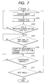
- Fig. 1 shows a conventional communication protocol and a data packet format.
- the transmission station before communication, performs carrier sense to check for a predetermined time whether a radio wave is being sent from another station, thereby avoiding interference between the radio wave from the self station and that from another station. If no radio waves from other stations are detected within the carrier sense time, communication is started; otherwise, carrier sense is continued.
- the transmission station sends a request to send (RTS) signal to the partner station (station on the reception side).
- RTS request to send
- the partner station Upon receiving the RTS, the partner station sends a clear to send (CTS) signal for allowing transmission.
- CTS clear to send
- the transmission station waits for a predetermined rise time for AGC (Automatic Gain Control) of the partner station and then transmits data packetized into a predetermined packet format.
- AGC Automatic Gain Control
- One packet has a header portion and a data portion including image or audio data.
- the header portion is made up of a synchronization signal (SYNC) and a portion including the partner station ID, a unique word representing the start of reception, a status, and a checksum.
- SYNC synchronization signal
- the transmission station Upon completing 1-packet data transmission, the transmission station transmits another RTS.
- the transmission station transmits packet data again after the elapse of the AGC rise time.
- the above operation is repeatedly performed such that an image for one frame or one field is sent as a plurality of packets.
- An object of the present invention is to solve the above-described problems.
- an image communication apparatus comprising:
- an image communication method comprising the steps of:
- an image communication method comprising the steps of:
- an image communication system comprising:
- an image communication processing program contained in a computer-readable medium comprising:
- an image communication processing program contained in a computer-readable medium comprising:
- Fig. 2 is a view showing the arrangement of an image transmission system of this embodiment.
- the image transmission system of this embodiment is comprised of a plurality of image communication apparatuses S1, S2, S3, V1, V2, and V3.
- Each of the apparatuses S1, S2, and S3 is a transmission station which radio-transmits image data sensed by a TV camera unit to a corresponding one of the partner stations V1, V2, and V2.
- each of the transmission stations S1, S2, and S3 has a TV camera unit such as a camcoder.
- An image sensed by the camera unit is compressed/coded and then modulated on a carrier wave having the same frequency in the 2.4 GHz band by spread spectrum modulation (to be referred to as SS modulation hereinafter) using code division multiplex.
- the modulated image data is asynchronously radio-transmitted from the antenna of each station to a corresponding one of the partner stations V1, V2, and V3.
- the transmission stations and the partner stations are in a one-to-one correspondence.
- a plurality of partner stations may correspond to one transmission station, or a plurality of transmission stations may correspond to one partner station.
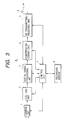
- Fig. 3 shows the arrangement of the transmission station S1 as the image communication apparatus of this embodiment.
- the remaining stations S2 and S3 also have the same arrangement as in Fig. 3.
- a camera unit 1 outputs an image signal sensed using an image sensing device such as a CCD.
- a CDS/AGC unit 2 performs noise removal and AGC (Automatic Gain Control) for the output signal from the camera unit 1.
- a digital signal processing unit 3 performs predetermined digital signal processing for the output signal from the CDS/AGC unit 2.
- a compression-coding unit 4 compresses/codes the output signal from the digital signal processing unit 3 using JPEG.
- the compression-coding unit 4 compresses/codes each image data for one picture. More specifically, the compression-coding unit 4 segments (divides) image data for one picture into a plurality of block data and performs DCT transformation, quantization, and variable length coding in units of block data. Each block data is made up of a plurality of pixel signal components.
- the compression-coding unit 4 breaks up compressed image data 401 for one picture into N packet data 402 and sequentially supplies each packet data to an SS transmitting/receiving unit 5.
- Each packet data 402 has a plurality of block data.
- the value N is variably set by a control unit 7.
- the control unit 7 sets an optimum value in accordance with the error state in the radio transmission channel or the amount of compressed image data for one picture.
- the SS transmitting/receiving unit 5 SS-modulates the compressed/coded image data by code division multiplex using a carrier wave in the 2.4 GHz band.
- the modulated image data is transmitted from the SS transmitting/receiving unit 5 through an antenna 6 by radio.
- the control unit 7 controls the SS transmitting/receiving unit 5 on the basis of the communication protocol of this embodiment (to be described later).
- the image data transmitted by ratio contains ID signals representing the transmission station and the corresponding partner station.
- the SS transmitting/receiving unit 5 receives a carrier wave signal having the above frequency, which is transmitted from one of the remaining transmission stations S2 and S3 and the partner stations V1, V2, and V3.
- the control unit 7 performs carrier sense on the basis of the received signal and simultaneously controls communication.
- the control unit 7 also controls the respective units 1 to 4 in a predetermined manner.
- the camera unit 1 may have an image recording/reproducing device such as a VTR for recording/reproducing the sensed image signal.
- an image recording/reproducing device such as a VTR for recording/reproducing the sensed image signal.
- a recording medium 8 stores program codes for realizing the communication protocol of this embodiment.
- This program codes can be read by a microcomputer incorporated in the control unit 7.
- the control unit 7 controls the operation of the SS transmitting/receiving unit on the basis of the program codes.
- Each of the image communication apparatuses S1, S2, and S3 of this embodiment may be a camcoder or a digital camera as far as it can realize the arrangement and function shown in Fig. 3.
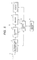
- Fig. 5 shows the arrangement of the partner station V1 as the image communication apparatus of this embodiment.
- the remaining partner stations V2 and V3 also have the same arrangement as in Fig. 5.
- an SS transmitting/receiving unit 11 demodulates a signal (image data or the like) addressed to the self station and received via an antenna 10.
- a decoding unit 12 expands/decodes the output signal from the SS transmitting/receiving unit 11.
- An encoder 13 converts the image data decoded by the decoding unit 12 into an NTSC image signal or the like.
- a monitor 14 displays the output signal from the encoder 13.
- a control unit 15 controls the SS transmitting/receiving unit 11 on the basis of the communication protocol of this embodiment and simultaneously controls the respective units 12 to 14 in a predetermined manner.
- a recording medium 16 stores program codes for realizing the communication protocol of this embodiment.
- This program codes can be read by a microcomputer incorporated in the control unit 15.
- the control unit 15 controls the operation of the SS transmitting/receiving unit 11 on the basis of the program codes.
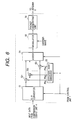
- Fig. 6 shows the arrangement of part of the SS transmitting/receiving unit 5. SS modulation based on code division multiplex of this embodiment will be described.
- compressed image data (serial data) for one packet, which is output from the compression-coding unit 4 is converted into n parallel data (each, parallel data has m bits) by an S/P converter 51.
- Each parallel data is supplied to multipliers 52 1 to 52 n in units of bits and multiplied by a corresponding one of n spreading codes PN 1 to PN n generated by a diffusion code generator 53.
- the outputs from the multipliers 52 1 to 52 n are added by an adder 54.
- a modulator 55 phase-modulates the output from the adder 54 on a carrier wave having an appropriate center frequency in, e.g., the 2.4 GHz band. With this processing, the SS transmitting/receiving unit 5 can obtain a modulated signal spread in a wide band.
- the S/P converter 51 converts the serially input packet data 402 into n parallel data 403.
- the adder 54 adds the products of the n parallel data 403 and the n diffusion codes PN 1 to PN n and supplies a sum 404 to a packet generating unit 56 through the modulator 55.
- the packet generating unit 56 adds header information to compressed image data for one packet, which is modulated by the modulator 55, to generate a communication packet 405.
- the header portion of the first communication packet 405 contains a synchronization signal (SYNC), partner station ID, a unique word representing the start of transmission, status information, and checksum.
- the SS transmitting/receiving unit 5 continuously transmits, via the antenna 6, N communication packets generated in the above procedure to the radio communication channel shared by the image communication apparatuses.
- the SS transmitting/receiving unit 5 can reduce the number of times of communication to 1/n, as compared to a case wherein compressed image data for one picture (image for one frame or one field) is SS-modulated using a diffusion code of one kind.
- the value n supplied to the S/P converter 51, the diffusion code generator 53, and the adder 54 is variably set by the control unit 7.
- the control unit 7 sets an optimum value in accordance with the error state in the radio transmission channel or the amount of compressed image data for one picture.
- the value n is kept unchanged for N communication packets formed from compressed image data for one picture. Therefore, a variation in processing time for each of the N communication packets is suppressed, and continuity of N communication packets is not impaired.
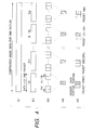
- Fig. 7 is a flow chart for explaining the processing procedure of the communication protocol of this embodiment.
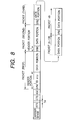
- Fig. 8 is a view showing the data packet format of this embodiment. The processing procedure of the communication protocol of this embodiment will be described below with reference to Figs. 7 and 8.
- step S701 the transmission station (S1, S2, or S3) performs carrier sense before starting communication of the self station to prevent interference between the radio wave from the self station and that from another station.
- carrier sense it is determined for a predetermined time whether another station is transmitting a radio wave.
- the transmission station When a radio wave from another station is detected during the predetermined time, the transmission station performs carrier sense again. If no radio wave from other stations is detected during the predetermined time, the transmission station executes processing from step S702.
- step S702 the transmission station (S1, S2, or S3) transmits a request to send (RTS) signal to the partner station (V1, V2, or V3).
- RTS request to send
- the partner station receives the RTS addressed to itself. If communication with the transmission station is possible, the partner station transmits a clear to send (CTS) signal as a response to the RTS.
- CTS clear to send
- step S703 the transmission station (S1, S2, or S3) waits for a CTS transmitted from the partner station during a predetermined waiting time Tw after sending the RTS. If a CTS is not received within the waiting time Tw, the transmission station executes carrier sense again.
- step S704 upon receiving the CTS from the partner station, the transmission station (S1, S2, or S3) waits for the rise time of AGC of the partner station.
- step S705 the transmission station starts radio transmission of compressed image data for one picture.
- the compressed image data for one picture e.g., one frame or one field
- N is an integer ⁇ 1
- compressed image data for one frame is transmitted by radio as 16 communication packets.
- the transmission station Upon completing transmission of the first packet, the transmission station sends the second packet.
- the header portion of the second packet contains only a synchronization signal (SYNC).
- the header portion of the third packet also contains only a synchronization signal.
- step S706 the transmission station detects whether transmission of the N communication packets is complete. If NO in step S706, all the remaining communication packets are transmitted.
- step S707 determines in step S707 whether image data for the next picture is to be transmitted. If YES in step S707, the transmission station executes carrier sense again. If NO in step S707, processing is ended.
- the transmission station (S1, S2, or S3) transmits a still image for one picture or a moving image for a plurality of pictures through the radio transmission channel shared by the remaining transmission stations.
- the transmission station of this embodiment continuously transmits compressed image data for one frame (or one field) as a plurality of packets. With this processing, an interrupt from another station during transmission can be prevented.
- the partner station can receive the image for one picture, i.e., one frame (or one field) and display it on the monitor without interruption.
- the recording medium storing the program codes of software for realizing the function of the first embodiment may be supplied to the control unit (including a microcomputer) of the system or apparatus of the first embodiment.
- control unit of the system or apparatus of the first embodiment reads out the program codes stored in the recording medium and controls the operation of the system or apparatus such that the function of the above embodiment is realized, thereby realizing the first embodiment.
- the recording medium 8 storing the program codes for realizing the function of the communication protocol shown in Fig. 7 in the first embodiment may be supplied to the control unit 7 shown in Fig. 3.
- the control unit 7 may read out the program codes stored in the recording medium 8 and control the processing circuits in Fig. 3 such that the function of the communication protocol of the first embodiment is realized.
- the program codes read out from the recording medium 8 realize the function of the first embodiment by themselves.
- the recording medium 8 storing the program codes partially constitutes the present invention.
- a floppy disk a hard disk, an optical disk, a magnetooptical disk, a CD-ROM, a CD-R, a magnetic tape, a nonvolatile memory card, a ROM, or the like can be used.
- the program codes of software for realizing the function of the first embodiment may be recorded in the recording medium 8 in advance or supplied from an external device through the SS transmitting/receiving unit 5.
- the present invention also incorporates a case wherein an OS (Operating System) or application software running on the control unit 7 controls the operation of the system or apparatus of the first embodiment on the basis of instructions of the program codes read out from the recording medium 8 to realize the function of the first embodiment.
- OS Operating System
- application software running on the control unit 7 controls the operation of the system or apparatus of the first embodiment on the basis of instructions of the program codes read out from the recording medium 8 to realize the function of the first embodiment.
- the present invention further incorporates a case wherein the program codes read out from the recording medium 8 are written in a memory of a function expansion board or function expansion unit connected to the control unit 7, and then, the control unit of the function expansion board or function expansion unit itself controls the operation of the apparatus or system of the first embodiment on the basis of instructions of the program codes to realize the function of the first embodiment.
- the AGC rise time may be inserted at various points during transmission of each packet, as needed.
- SS modulation is used as the scheme of modulating data to be transmitted by radio.
- another modulation scheme may be used.
- the present invention can be applied to a system wherein each of a plurality of radio stations asynchronously and time-divisionally communicates with the partner station using a common radio transmission channel while checking transmission of another radio station for a predetermined time.
Abstract
Description
Claims (21)
- An image communication apparatus comprising:generation means for generating a plurality of communication packets from image data for one picture; andcommunication means for continuously radio-transmitting the plurality of communication packets, output from said generation means, through a radio transmission channel shared by a plurality of devices.
- An apparatus according to claim 1, wherein
said generation means segments data contained in the communication packet into n data sequences, multiplies each data sequence by one of n different diffusion codes, and multiplexes products for the data sequences. - An apparatus according to claim 2, wherein
the value n remains the same for the plurality of communication packets. - An apparatus according to claim 1, wherein
said generation means modulates each of the plurality of communication packets by spread spectrum modulation. - An apparatus according to claim 1, wherein
said communication means transmits a transmission request to a destination before transmission of the plurality of communication packets, and executes transmission of the plurality of communication packets upon detecting a response to the transmission request within a predetermined time. - An apparatus according to claim 1, wherein
a header portion of the first packet of the plurality of communication packets contains a synchronization signal and ID information for identifying a destination, and header portions of the remaining packets do not contain the ID information. - An apparatus according to claim 1, wherein
the image data is compressed and coded in units of pictures. - An apparatus according to claim 1, wherein
said image communication apparatus further comprises image sensing means, and image data sensed by said image sensing means is supplied to said generation means. - An apparatus according to claim 1, whereinsaid image communication apparatus further comprises control means for controlling operation of said communication means, andsaid control means controls the operation of said communication means on the basis of a program for realizing a function of performing carrier sense in the radio transmission channel for a predetermined time before transmission of the plurality of communication packets, transmitting a transmission request to a destination in accordance with a carrier sense result, and executing transmission of the plurality of communication packets upon detecting a response to the transmission request within a predetermined time.
- An apparatus according to claim 1, wherein
said image communication apparatus comprises a camcoder or digital camera. - An image communication method comprising the steps of:generating a plurality of communication packets from image data for one picture; andcontinuously radio-transmitting the plurality of communication packets through a radio transmission channel shared by a plurality of devices.
- A method according to claim 11, wherein
data contained in the communication packet is segmented into n data sequences, the n data sequences being multiplied by n different diffusion codes and multiplexed. - A method according to claim 11, wherein
the image communication method further comprises modulating each of the plurality of communication packets by spread spectrum modulation. - A method according to claim 11, wherein
the image communication method further comprises transmitting a transmission request to a destination before transmission of the plurality of communication packets, and executing radio transmission of the plurality of communication packets upon detecting a response to the transmission request within a predetermined time. - A method according to claim 11, wherein
a header portion of the first packet of the plurality of communication packets contains a synchronization signal and ID information for identifying a destination, and header portions of the remaining packets do not contain the ID information. - An image communication method comprising the steps of:performing carrier sense in a radio transmission channel shared by a plurality of devices for a predetermined time;transmitting a transmission request to a destination in accordance with a carrier sense result; andcontinuously transmitting a plurality of communication packets formed from image data for one picture upon detecting a response to the transmission request within a predetermined time.
- An image communication system comprising:a transmission apparatus and a reception apparatus,wherein said transmission apparatus performs carrier sense in a radio transmission channel shared by a plurality of devices, and transmits a transmission request to said reception apparatus in accordance with a carrier sense result,said reception apparatus returns a response to the transmission request when processing corresponding to the transmission request can be performed, andsaid transmission apparatus continuously transmits a plurality of communication packets formed from image data for one picture to said reception apparatus upon detecting the response to the transmission request within a predetermined time.
- An image communication processing program is contained in a computer-readable medium, comprising:a program code for generating a plurality of communication packets from image data for one picture; anda program code for continuously radio-transmitting the plurality of communication packets through a radio transmission channel shared by a plurality of devices.
- An image communication processing program contained in a computer-readable medium, comprising:a program code for performing carrier sense in a radio transmission channel shared by a plurality of devices for a predetermined time;a program code for transmitting a transmission request to a destination in accordance with a carrier sense result; anda program code for continuously transmitting a plurality of communication packets formed from image data for one picture upon detecting a response to the transmission request within a predetermined time.
- A transmitted image signal wherein image data of a single picture is segmented amongst a plurality of transmitted data packets, the first packet thereof having a header portion containing both an ID signal and a synchronization signal, the remainder packets thereof having a header portion containing only a synchronization signal, said remainder packets following said first packet without interruption.
- A receiver for receiving the signal of claim 20 having:means of receiving a request-to-send signal sent from a transmitter;means of responding to said request-to-send signal by returning a clear-to-send signal, when ready to receive image transmission; andmeans of receiving and processing said signal of claim 20 to extract the image data of the single picture represented by the content of the plurality of transmitted data packets.
Applications Claiming Priority (3)
| Application Number | Priority Date | Filing Date | Title |
|---|---|---|---|
| JP20021897 | 1997-07-25 | ||
| JP20021897A JP3492157B2 (en) | 1997-07-25 | 1997-07-25 | Imaging device and image transmission device |
| JP200218/97 | 1997-07-25 |
Publications (3)
| Publication Number | Publication Date |
|---|---|
| EP0893905A2 true EP0893905A2 (en) | 1999-01-27 |
| EP0893905A3 EP0893905A3 (en) | 2001-01-31 |
| EP0893905B1 EP0893905B1 (en) | 2007-01-24 |
Family
ID=16420781
Family Applications (1)
| Application Number | Title | Priority Date | Filing Date |
|---|---|---|---|
| EP19980305862 Expired - Lifetime EP0893905B1 (en) | 1997-07-25 | 1998-07-22 | Image communication apparatus, method, and system, and image communication processing program contained in computer-readable medium |
Country Status (4)
| Country | Link |
|---|---|
| US (1) | US6385177B1 (en) |
| EP (1) | EP0893905B1 (en) |
| JP (1) | JP3492157B2 (en) |
| DE (1) | DE69836939T2 (en) |
Cited By (1)
| Publication number | Priority date | Publication date | Assignee | Title |
|---|---|---|---|---|
| WO2004006508A1 (en) | 2002-07-08 | 2004-01-15 | Matsushita Electric Industrial Co., Ltd. | Radio communication method, radio communication terminal, and radio lan system |
Families Citing this family (13)
| Publication number | Priority date | Publication date | Assignee | Title |
|---|---|---|---|---|
| JP2000209586A (en) * | 1999-01-18 | 2000-07-28 | Fujitsu Ltd | Picture transmission equipment |
| US8212893B2 (en) * | 1999-06-08 | 2012-07-03 | Verisign, Inc. | Digital camera device and methodology for distributed processing and wireless transmission of digital images |
| US7372485B1 (en) | 1999-06-08 | 2008-05-13 | Lightsurf Technologies, Inc. | Digital camera device and methodology for distributed processing and wireless transmission of digital images |
| US7369161B2 (en) * | 1999-06-08 | 2008-05-06 | Lightsurf Technologies, Inc. | Digital camera device providing improved methodology for rapidly taking successive pictures |
| US7103357B2 (en) * | 1999-11-05 | 2006-09-05 | Lightsurf Technologies, Inc. | Media spooler system and methodology providing efficient transmission of media content from wireless devices |
| US7847833B2 (en) * | 2001-02-07 | 2010-12-07 | Verisign, Inc. | Digital camera device providing improved methodology for rapidly taking successive pictures |
| GB0015454D0 (en) * | 2000-06-26 | 2000-08-16 | Koninkl Philips Electronics Nv | Data delivery through beacons |
| US7305354B2 (en) | 2001-03-20 | 2007-12-04 | Lightsurf,Technologies, Inc. | Media asset management system |
| US20020193157A1 (en) * | 2001-06-18 | 2002-12-19 | Canon Kabushiki Kaisha | Computer device for implementing a trading card game and control method therefor, program executed by computer device, controller, system, and game cards |
| US7724281B2 (en) | 2002-02-04 | 2010-05-25 | Syniverse Icx Corporation | Device facilitating efficient transfer of digital content from media capture device |
| DE10218425A1 (en) * | 2002-04-24 | 2003-11-06 | Grundig Ag I Ins | Method and device for synchronizing a receiver with a transmitter during data transmission over an asynchronous network |
| KR100540662B1 (en) | 2004-01-07 | 2006-01-12 | 삼성전자주식회사 | Method and apparatus for setting channel automatically in wireless transceiver system |
| DE102017130980A1 (en) * | 2017-12-21 | 2019-06-27 | Schölly Fiberoptic GmbH | Image transfer arrangement and method for image transfer |
Citations (3)
| Publication number | Priority date | Publication date | Assignee | Title |
|---|---|---|---|---|
| WO1995032594A1 (en) * | 1994-05-20 | 1995-11-30 | Ntt Mobile Communication Network Inc. | Cellular mobile radiocommunication system soft-handover scheme |
| WO1996027250A1 (en) * | 1995-02-28 | 1996-09-06 | Qualcomm Incorporated | Method and apparatus for providing variable rate data in a communications system using non-orthogonal overflow channels |
| US5592536A (en) * | 1992-10-22 | 1997-01-07 | Te Electronics, Inc. | Apparatus and method for fast initiation of connection in cordless telephones |
Family Cites Families (2)
| Publication number | Priority date | Publication date | Assignee | Title |
|---|---|---|---|---|
| JPH09172446A (en) * | 1995-10-20 | 1997-06-30 | Fuji Xerox Co Ltd | Lan of multiple bus system and radio lan |
| JPH09252491A (en) * | 1997-01-31 | 1997-09-22 | Hitachi Ltd | Radio terminal equipment |
-
1997
- 1997-07-25 JP JP20021897A patent/JP3492157B2/en not_active Expired - Fee Related
-
1998
- 1998-07-22 DE DE1998636939 patent/DE69836939T2/en not_active Expired - Lifetime
- 1998-07-22 EP EP19980305862 patent/EP0893905B1/en not_active Expired - Lifetime
- 1998-07-23 US US09/121,059 patent/US6385177B1/en not_active Expired - Lifetime
Patent Citations (3)
| Publication number | Priority date | Publication date | Assignee | Title |
|---|---|---|---|---|
| US5592536A (en) * | 1992-10-22 | 1997-01-07 | Te Electronics, Inc. | Apparatus and method for fast initiation of connection in cordless telephones |
| WO1995032594A1 (en) * | 1994-05-20 | 1995-11-30 | Ntt Mobile Communication Network Inc. | Cellular mobile radiocommunication system soft-handover scheme |
| WO1996027250A1 (en) * | 1995-02-28 | 1996-09-06 | Qualcomm Incorporated | Method and apparatus for providing variable rate data in a communications system using non-orthogonal overflow channels |
Non-Patent Citations (1)
| Title |
|---|
| PATENT ABSTRACTS OF JAPAN vol. 1998, no. 01, 30 January 1998 (1998-01-30) & JP 09 252491 A (HITACHI LTD;HITACHI TELECOM TECHNOL LTD), 22 September 1997 (1997-09-22) * |
Cited By (5)
| Publication number | Priority date | Publication date | Assignee | Title |
|---|---|---|---|---|
| WO2004006508A1 (en) | 2002-07-08 | 2004-01-15 | Matsushita Electric Industrial Co., Ltd. | Radio communication method, radio communication terminal, and radio lan system |
| EP1521399A1 (en) * | 2002-07-08 | 2005-04-06 | Matsushita Electric Industrial Co., Ltd. | Radio communication method, radio communication terminal, and radio lan system |
| CN100350773C (en) * | 2002-07-08 | 2007-11-21 | 松下电器产业株式会社 | Radio communication method, radio communication terminal and radio LAN system |
| US7804813B2 (en) | 2002-07-08 | 2010-09-28 | Panasonic Corporation | Radio communication method, radio communication terminal and radio LAN system |
| EP1521399A4 (en) * | 2002-07-08 | 2010-10-13 | Panasonic Corp | Radio communication method, radio communication terminal, and radio lan system |
Also Published As
| Publication number | Publication date |
|---|---|
| EP0893905B1 (en) | 2007-01-24 |
| JPH1146294A (en) | 1999-02-16 |
| JP3492157B2 (en) | 2004-02-03 |
| DE69836939D1 (en) | 2007-03-15 |
| EP0893905A3 (en) | 2001-01-31 |
| US6385177B1 (en) | 2002-05-07 |
| DE69836939T2 (en) | 2007-05-31 |
Similar Documents
| Publication | Publication Date | Title |
|---|---|---|
| US6385177B1 (en) | Image communication apparatus, method, and system, and image communication processing program contained in computer-readable medium | |
| EP0668669A1 (en) | Data communication system controlling the information transmission bit rate or source encoding rate | |
| US20010043786A1 (en) | Video camera and recording and reproducing apparatus | |
| US20050124384A1 (en) | Communication apparatus capable of communicating via different types of communication lines and control method thereof | |
| EP2053797A1 (en) | Multichannel data transfer apparatus and method | |
| US6466587B1 (en) | Wireless transmitting method | |
| US5463477A (en) | Mobile communication method and mobile communication system for deleting fill code in radio circuit | |
| US6330695B1 (en) | Data communications apparatus, data communications method, program for coding information data contained in computer readable medium | |
| US20050288010A1 (en) | Radio communication apparatus and radio communication method | |
| EP1670145A1 (en) | Electronic device and control method therefor | |
| US6804535B2 (en) | Communication apparatus capable of connecting information processing apparatus | |
| US6771936B2 (en) | Apparatus and method for wire or radio transmission information signal processing | |
| JP2001313930A (en) | Video transmission system and video transmitter | |
| JP3413091B2 (en) | Image transmission device | |
| JP2001086496A (en) | Device and method for transmitting image | |
| JP2000244919A (en) | Video transmitter and its method | |
| JPH10145318A (en) | Communication method and communication equipment | |
| JPH10145316A (en) | Communication method and communication equipment | |
| US20040090392A1 (en) | Image transmission system | |
| JPH11261977A (en) | Image transmission system, device and method | |
| JP2001231073A (en) | Radio communication system | |
| US20040037321A1 (en) | Network apparatus and network method | |
| JP2944604B2 (en) | Radio mobile station and image receiving system having the same | |
| JPH09214912A (en) | Communication equipment, its method and system | |
| JP3375114B2 (en) | Wireless communication device |
Legal Events
| Date | Code | Title | Description |
|---|---|---|---|
| PUAI | Public reference made under article 153(3) epc to a published international application that has entered the european phase |
Free format text: ORIGINAL CODE: 0009012 |
|
| AK | Designated contracting states |
Kind code of ref document: A2 Designated state(s): DE FR GB |
|
| AX | Request for extension of the european patent |
Free format text: AL;LT;LV;MK;RO;SI |
|
| PUAL | Search report despatched |
Free format text: ORIGINAL CODE: 0009013 |
|
| AK | Designated contracting states |
Kind code of ref document: A3 Designated state(s): AT BE CH CY DE DK ES FI FR GB GR IE IT LI LU MC NL PT SE |
|
| AX | Request for extension of the european patent |
Free format text: AL;LT;LV;MK;RO;SI |
|
| 17P | Request for examination filed |
Effective date: 20010615 |
|
| AKX | Designation fees paid |
Free format text: DE FR GB |
|
| GRAP | Despatch of communication of intention to grant a patent |
Free format text: ORIGINAL CODE: EPIDOSNIGR1 |
|
| GRAS | Grant fee paid |
Free format text: ORIGINAL CODE: EPIDOSNIGR3 |
|
| GRAA | (expected) grant |
Free format text: ORIGINAL CODE: 0009210 |
|
| AK | Designated contracting states |
Kind code of ref document: B1 Designated state(s): DE FR GB |
|
| REG | Reference to a national code |
Ref country code: GB Ref legal event code: FG4D |
|
| REF | Corresponds to: |
Ref document number: 69836939 Country of ref document: DE Date of ref document: 20070315 Kind code of ref document: P |
|
| ET | Fr: translation filed | ||
| PLBE | No opposition filed within time limit |
Free format text: ORIGINAL CODE: 0009261 |
|
| STAA | Information on the status of an ep patent application or granted ep patent |
Free format text: STATUS: NO OPPOSITION FILED WITHIN TIME LIMIT |
|
| 26N | No opposition filed |
Effective date: 20071025 |
|
| PGFP | Annual fee paid to national office [announced via postgrant information from national office to epo] |
Ref country code: DE Payment date: 20140731 Year of fee payment: 17 |
|
| PGFP | Annual fee paid to national office [announced via postgrant information from national office to epo] |
Ref country code: FR Payment date: 20140728 Year of fee payment: 17 Ref country code: GB Payment date: 20140724 Year of fee payment: 17 |
|
| REG | Reference to a national code |
Ref country code: DE Ref legal event code: R119 Ref document number: 69836939 Country of ref document: DE |
|
| GBPC | Gb: european patent ceased through non-payment of renewal fee |
Effective date: 20150722 |
|
| PG25 | Lapsed in a contracting state [announced via postgrant information from national office to epo] |
Ref country code: DE Free format text: LAPSE BECAUSE OF NON-PAYMENT OF DUE FEES Effective date: 20160202 Ref country code: GB Free format text: LAPSE BECAUSE OF NON-PAYMENT OF DUE FEES Effective date: 20150722 |
|
| REG | Reference to a national code |
Ref country code: FR Ref legal event code: ST Effective date: 20160331 |
|
| PG25 | Lapsed in a contracting state [announced via postgrant information from national office to epo] |
Ref country code: FR Free format text: LAPSE BECAUSE OF NON-PAYMENT OF DUE FEES Effective date: 20150731 |