The present invention relates to a refrigerator comprising a cooling compartment, an
aperture opening into the compartment, a heat pump and cool air distributing means
for supplying cool air generated by the heat pump to the compartment through the
aperture.
Generally, a refrigerator has a cabinet in which there are a freezing compartment and
a fresh food compartment. These compartments are separated by a partition wall.
Doors are provided at the front of the freezing and cooling compartments. A cooling
system supplies the freezing compartment and the fresh food compartment with cool
air and comprises a compressor, a condenser and an evaporator. The cool air
generated by the evaporator flows along a supply duct formed at the back of each
compartment, and is then supplied into each cooling compartment through cool air
discharge ports opening thereinto by a fan.
In such a conventional refrigerator, however, cool air tends to be supplied into a
particular area of the cooling compartment and other areas tend to be less well
served. Consequently, a uniform temperature is not maintained throughout the
cooling compartment.
This problem has been addressed by providing cool air discharge ports in the side
walls of the cooling compartment as well as in its rear wall. However, there may be
still a dead-zone at an edge area which is not supplied with the cool air sufficiently.
Furthermore, the ducting required to supply cool air from the sides of the cooling
compartment reduces the space available for food and increases the cost of
manufacture.
The problem of adequately distributing cool air in a refrigerator is worse for larger
refrigerators.
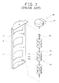
Figures 1 through 3 are a side view, a partial enlarged sectional view, and an exploded
perspective view of the main elements of a refrigerator having a device for dispersing
cool air as disclosed in WO-A-95/27278.
Referring to Figures 1 to 3, a refrigerator comprises freezing and fresh food
compartments 2, 3 in a cabinet 1, which are separated from each other by a partition
5. Respective doors 6, 7 are provided for closing the compartments 2, 3. A cooling
system, comprising a compressor 11, a condenser (not shown), a freezing
compartment evaporator 12a, and a fresh food compartment evaporator 12b, is
installed in the cabinet 1. Cool air generated by the evaporators 12a, 12b is supplied
to the corresponding compartments 2, 3 by a freezing compartment fan 13a and a
fresh food compartment fan 13b respectively.
A partially cylindrical duct plate 9 is attached to an inner wall plate 23 forming the
rear inner wall surface of the fresh food compartment 3. The duct plate 9 has cool air
discharge ports 16, opening into the fresh food compartment 3, formed in it. A
supply duct 15 and a return duct 17, separated from each other by a seal plate 25, are
provided between the duct plate 9 and the rear wall 4 of the cabinet 1. A duct
member 21, for guiding downwards cool air blown by the fresh food compartment
fan 13b, is installed in the supply duct 15. Cool air generated by the fresh food
compartment evaporator 12b is blown by the fresh food compartment fan 13b and
then supplied to the fresh food compartment 3 via the supply duct 15 and the cool air
discharge ports 16.
A cool air dispersing device 130 is installed in the supply duct 15. The cool air
dispersing device 130 comprises a rotational shaft 131 having a vertical axis, cool air
dispersing blades 132 assembled with the rotational shaft 131 in correspondence with
respective cool air discharge ports 16, and a driving motor 135 for rotating the
rotational shaft 131. Each of the cool air dispersing blades 132 comprises three discs
136, 137, 138 disposed in parallel with each other along the shaft 131, and first and
second blade parts 133, 134 disposed between pairs of the discs 136, 137, 138. Each of
the blade parts 133, 134 is curved so that its cross-section is loosely S-shaped. The
blade parts 133, 134 are bent in opposite directions to each other.
In a refrigerator having the above-described constitution, when the driving motor 131
rotates the rotational shaft 131 at a low speed, cool air flowing along the supply duct
15 changes its direction along the curved surfaces of the cool air dispersing blades 132,
and is directed into the fresh food compartment 3 so as to disperse horizontally.
When concentrated cooling in a specific area is needed, the driving motor 135 stops
the rotational shaft 131 so that the cool air dispersing blades 132 direct cool air to the
specific area. However, since the blade parts 133, 134 of the cool air dispersing device
130 are S-shaped, the left or right sides of the fresh food compartment 3 may not be
supplied with the cool air sufficiently and the smooth flow of cool air may be
impeded by a vortices in the cool air formed about the cool air discharge ports 16.
The present invention has been proposed to overcome the above-described problems
in the prior art, and accordingly it is the object of the present invention to provide a
refrigerator having a cool air dispersing device capable of preventing vortex of cool
air and distributing the cool air effectively.
A refrigerator according to the present invention is characterised by a pivotable blade
for directing cool air being supplied to the compartment through the aperture, drive
means for pivoting the blade, temperture sensing means for sensing the temperature
distribution in the compartment and control means responsive to the output of the
temperature sensing means to control the drive means such that the blade moves so as
to direct cool air so as to tend to reduce temperature variations across the
compartment.
The blade maybe pivotable about a vertical axis or about horizontal axis.
Preferably, one blade is pivotable about a vertical axis and a further blade for
directing cool air being supplied to the compartment through the aperture is
pivotable about a horizontal axis. The further blade is preferably driven by said drive
means.
Preferably, the control means operates to continuously rotate the or each blade when
the temperature variation across the compartment meets a predetermined criteria, for
example a temperature differential.
An embodiment of the present invention will now be described, by way of example,
with reference to Figures 4 to 14 of the accompanying drawings, in which:-
Hereinafter, an exemplary embodiment of the present invention will be described in
detail with reference to the accompanying drawings. Parts that are the same as or
similar to parts shown in Figures 1 through 3 will be identified with the same
reference numerals. The description of the parts which are substantially the same as
those of the prior art will be omitted.
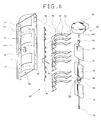
Referring to Figures 4 and 5, a refrigerator according to the present invention
comprises a freezing compartment 2 and a cooling compartment 3 in a cabinet 1.
The compartments 2, 3 are separated by a horizontal partition. Doors 6, 7 are
provided respectively for the compartments 2, 3. Shelves 8 for supporting food are
provided in the fresh food compartment 3 and divide it into three areas one above
another. A special fresh chamber 18 for storing food that requires a specific
temperature range is formed at the top of the fresh food compartment 3 and a
vegetable chamber 19 for storing vegetables is formed at the bottom of the fresh food
compartment 3. A heat pump, comprising a compressor 11, a condenser (not
shown), a freezing compartment evaporator 12a, and a fresh food compartment
evaporator 12b, is installed in the cabinet 1. Cool air generated by the evaporators
12a, 12b is supplied into the corresponding cooling compartments 2, 3 by the freezing
compartment fan 13a and the fresh food compartment fan 13b. A supply duct 15 and
a return duct 17 are provided at the back of the fresh food compartment 3. The cool
air generated by the fresh food compartment evaporator 12b is driven by the fresh
food compartment fan 13b into the fresh food compartment 3 via the supply duct 15
and the cool air discharge ports 16. A device for dispersing the cool air horizontally
is installed in the supply duct 15. A pair of temperature sensors 9a, 9b are installed in
the fresh food compartment 3. The first temperature sensor 9a is installed in the
upper left portion of the fresh food compartment 3 and the second temperature
sensor 9b is installed in the lower right portion of the fresh food compartment 3.
The refrigerator has a device 30 for dispersing cool air horizontally and a device 40
for dispersing the cool air vertically. The horizontally-dispersing device 30 has a
verical shaft 31, three horizontally-dispersing blades 33 having the shape of a planar
plate, and a driving motor 35 for rotating the rotational shaft 31. Three horizontally-dispersing
blades 33 are spaced along the shaft 31 near respective cool air discharge
ports 16. A coupling part 39 at the upper end of the rotational shaft 31 is coupled to
a drive shaft 36 of the driving motor 35 and a journal part 32 at the bottom of the
rotational shaft 31 is rotatably received in a bearing hole 9g at the bottom of the duct
plate 9. It is preferable that the driving motor 35 be a stepping motor whose angular
stop position can be controlled. Thus, when the driving motor 35 operates, the
horizontally-dispersing blades 33 are rotated by the rotational shaft 31, and cool air is
discharged through the cool air discharge ports 16 and dispersed horizontally.
The vertically-dispersing device 40 comprises a plurality of vertically-dispersing
blades 57 which are disposed near the cool air discharge ports 16 and which are
capable of pivoting about respective horizontal axes, a vertically reciprocable link
member 61 in the supply duct 15, and a raising and lowering cam 63 for raising and
lowering the link member 61. The vertically-dispersing blades 57 are arcute so as to
accommodate the horizontally-dispersing blades 33, and a horizontal stub shaft 53
extend horizontally from the left and right ends thereof. The duct plate 9 has two
opposed flange parts 9e which extend backward from its side margins. The flange
parts 9e have a plurality of shaft holes 9f for receiving and rotatably supporting the
stub shafts 53. The link member 61 is disposed parallel to the rotational shaft 31.
The link member 61 is rod-shaped and has a plurality of partially ring-shaped hinge
assembly parts 62 which protrude towards respective vertical- dispersing blades 57.
Each of the vertically-dispersing blades 57 has a horizontal, cylindrical hinge part 55
at the middle of its front edge. The hinge assembly parts 62 are engaged by the hinge
parts 73 so as to be capable of rotating relatively thereto. The raising and lowering
cam 63 is installed on the rotational shaft 31.
The raising and lowering cam 63 comprises a cylindrical cam body 66 and a cam
groove 65 formed on the outer surface of the cam body 66. The cam groove 65 is a
closed loop having a raising and lowering profile. On the link member 61 is provided
an operation part 67 protruding transversely to the longitudinal direction of the link
member and the free end of the operation part 67 is received in the cam groove 65.
Furthermore, the link member 61 has a guiding piece 69 protruding toward the duct
plate 9. The guiding piece 69 is accommodated in the raising and lowering guiding
part 49 formed on the inner wall of the duct plate 9. The raising and lowering
guiding part 49 accommodates the guiding piece 69 so as to guide it up and down and
prevent the link member 61 from rotating.
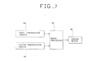
Referring to Figure 7, the cool air dispersing device is controlled by a microprocessor
70. The microprocessor 70 receives signals from the first and second temperature
sensors 9a, 9b and calculates the temperture distribution on the basis of the sensed
temperatures. The microprocessor 70 controls the driving motor 35 according to the
calculated temperature distribution. Furthermore, although it is not shown in Figure
7, the microprocessor 70 also controls the compressor 11 and the fans 13a, 13b to
control the generation and supply of the cool air.
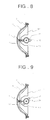
Referring to Figure 8, when the horizontally-dispersing blades 33 are directed to the
front, cool air in the supply duct 15 is discharged directly to the front along both
sides of the horizontally-dispersing blades 33. When the horizontally-dispersing
blades 33 are rotated to the left or the right as shown in Figures 9 and 10, cool air is
discharged toward the left or to the right.
While the horizontally-dispersing device 30 is operating, the raising and lowering cam
63 rotates with the rotational shaft 31, and the link member 61 is raised and lowered
by the operation part 67 which is engaged with the cam groove 65 of the raising and
lowering cam 63. The up and down movement of the link member 61 causes
pivoting of the vertically-dispersing blades 57 relatively to the horizontal rotational
shaft 53 through the hinge assembly part 62 and the hinge part 55 of the vertically-dispersing
blades 57.
The raising and lowering of the link member 61 is guided vertically by the guiding
piece 69 and the raising and lowering guiding part 49. Therefore, the link member 61
does not rotate but reciprocates in the vertical direction while the raising and
lowering cam 63 rotates.
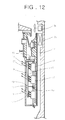
Referring to Figure 11, while the vertically-dispersing blades 71 are kept horizontal,
cool air is discharged horizontally. When the rotational shaft 31 rotates by about 90
degrees, the vertically-dispersing blades 57 are tilted upward as shown in Figure 12,
and, in this situation, cool air is discharged upward to the upper area of the fresh food
compartment 3. As the rotational shaft 31 further rotates by about 90 degrees from
the position shown in Figure 12, the vertically-dispersing blades 57 are returned to
the horizontal state as shown in Figure 11, and as it further rotates by about 90
degrees, the vertically-dispersing blades 57 are tilted downward as shown in Figure
13. In this situation, the cool air is discharged downward.
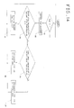
The operation of the above-described refrigerator will now be described with
reference to Figure 14.
The microprocessor 70 checks (step S1) whether the fresh food compartment fan 13b
is running or not. If the fresh food compartment fan 13b is running, the
microprocessor 70 senses the distribution of the temperature in the fresh food
compartment 3 in order to perform the concentrative cooling according to the
present invention.
The microprocessor 70 senses (step S2) the temperature in the fresh food
compartment 3 using the first and second temperature sensors 9a, 9b, and calculates
(step S3) the difference between the temperatures at the sensed positions. The
microprocessor 70 calculates the degree of the deviation of the temperatures on the
basis of whether the temperature difference is over a predetermined value X or not.
In such a situation, the predetermined value X is determined in consideration of the
kind, size, and cooling capacity of the refrigerator, and is preferably determined to be
from 2 to 3 degrees centigrade.
If the temperature difference is below the predetermined value X, the microprocessor
70 rotates (step S4) the rotational shaft 31 continuously in a constant speed.
Therefore, the cool air is dispersed uniformly by the rotating horizontally-dispersing
blades 33. The vertically-dispersing device 40 operates together while the
horizontally-dispersing device 30 is operating, so cool air is dispersed uniformly in
horizontal direction as well as vertical direction. Furthermore, since the
horizontally-dispersing blades 33 are planar, vortices in the cool air flow are not
generated by the horizontally-dispersing blades 33.
If the temperature difference is over the predetermined value X, the microprocessor
70 compares (step S5) the temperature of the first area sensed by the first temperature
sensor 9a with the temperature of the second area sensed by the second temperature
sensor 9b, and stops the driving motor 35 so that the horizontally-dispersing blades
33 are directed to the area of higher temperature. Thus, the concentrated cooling of a
high temperature area is realized.
In other words, if the temperature of the first area is higher than that of the second
area, the microprocessor 70 controls (step S6) the driving motor 35 so that the
horizontally-dispersing blades 33 are rotated right as shown in Figure 10. In this
situation, the vertically-dispersing blades 57 are rotated upward as shown in Figure
13. Then the cool air is discharged to be concentrated on the first area.
According to a similar manner, if the temperature of the second area is higher than
that of the first area, the microprocessor 70 controls (step S7) the driving motor 35 so
that the horizontally-dispersing blades 33 are rotated left as shown in Figure 9. In
this situation, the vertically-dispersing blades 57 are rotated downward as shown in
Figure 12. Then cool air is discharged so as to be concentrated on the second area.
Since the cool air is discharged to the high temperature area in a concentrative
manner, the temperature in the fresh food compartment 3 is maintained uniform.
In the present embodiment, horizontally-dispersing blades 33 are disposed in
correspondence with respective cool air discharge ports 16. However, a single long
blade, extending past all of the cool air discharge ports 16, could be used.
Furthermore, in the present embodiment, the vertically-dispersing blades 57 operate
together with the horizontally-dispersing blades 33. However, they could be driven
independently. That is, if an additional driving motor controlled by the
microprocessor 70 is provided, and the link member 61 is operated not by the raising
and lowering cam 63 but by the additional driving motor, it is possible to control
independently the angular stop positions of the vertically-dispersing blades 57. Then,
the concentrative cooling on a specific area or the dispersing of the cool air by
continuous reciprocation can be performed in the vertical direction as well. In this
case, it is preferable that a plurality of temperature sensors are provided at a plurality
of respective positions. Using the plurality of temperature sensors, the highest
temperature area can be detected from among a plurality of areas. The vertically-dispersing
blades 57 and the horizontally-dispersing blades 33, which are controlled
independently of each other, can then direct cool air to the detected high temperature
area.