EP0893613B1 - Cardan shaft - Google Patents
Cardan shaft Download PDFInfo
- Publication number
- EP0893613B1 EP0893613B1 EP98305575A EP98305575A EP0893613B1 EP 0893613 B1 EP0893613 B1 EP 0893613B1 EP 98305575 A EP98305575 A EP 98305575A EP 98305575 A EP98305575 A EP 98305575A EP 0893613 B1 EP0893613 B1 EP 0893613B1
- Authority
- EP
- European Patent Office
- Prior art keywords
- female
- male
- radius
- generally linear
- assembly
- Prior art date
- Legal status (The legal status is an assumption and is not a legal conclusion. Google has not performed a legal analysis and makes no representation as to the accuracy of the status listed.)
- Expired - Lifetime
Links
- 230000000295 complement effect Effects 0.000 claims description 3
- 230000005540 biological transmission Effects 0.000 description 6
- 230000000712 assembly Effects 0.000 description 3
- 238000000429 assembly Methods 0.000 description 3
- 238000002347 injection Methods 0.000 description 3
- 239000007924 injection Substances 0.000 description 3
- 230000007812 deficiency Effects 0.000 description 2
- 238000005242 forging Methods 0.000 description 2
- 238000003754 machining Methods 0.000 description 2
- 238000004519 manufacturing process Methods 0.000 description 2
- 239000002184 metal Substances 0.000 description 2
- 229910052751 metal Inorganic materials 0.000 description 2
- 238000004513 sizing Methods 0.000 description 2
- 229920001187 thermosetting polymer Polymers 0.000 description 2
- 239000011800 void material Substances 0.000 description 2
- 229910001141 Ductile iron Inorganic materials 0.000 description 1
- 238000005266 casting Methods 0.000 description 1
- 239000011248 coating agent Substances 0.000 description 1
- 238000000576 coating method Methods 0.000 description 1
- 230000008878 coupling Effects 0.000 description 1
- 238000010168 coupling process Methods 0.000 description 1
- 238000005859 coupling reaction Methods 0.000 description 1
- 238000005553 drilling Methods 0.000 description 1
- 230000006698 induction Effects 0.000 description 1
- 238000003780 insertion Methods 0.000 description 1
- 230000037431 insertion Effects 0.000 description 1
- 239000000463 material Substances 0.000 description 1
- 238000003801 milling Methods 0.000 description 1
- 238000012986 modification Methods 0.000 description 1
- 230000004048 modification Effects 0.000 description 1
- 239000012260 resinous material Substances 0.000 description 1
- 238000005096 rolling process Methods 0.000 description 1
- 238000010079 rubber tapping Methods 0.000 description 1
- XLYOFNOQVPJJNP-UHFFFAOYSA-N water Substances O XLYOFNOQVPJJNP-UHFFFAOYSA-N 0.000 description 1
Images



Classifications
-
- G—PHYSICS
- G11—INFORMATION STORAGE
- G11B—INFORMATION STORAGE BASED ON RELATIVE MOVEMENT BETWEEN RECORD CARRIER AND TRANSDUCER
- G11B5/00—Recording by magnetisation or demagnetisation of a record carrier; Reproducing by magnetic means; Record carriers therefor
- G11B5/48—Disposition or mounting of heads or head supports relative to record carriers ; arrangements of heads, e.g. for scanning the record carrier to increase the relative speed
- G11B5/58—Disposition or mounting of heads or head supports relative to record carriers ; arrangements of heads, e.g. for scanning the record carrier to increase the relative speed with provision for moving the head for the purpose of maintaining alignment of the head relative to the record carrier during transducing operation, e.g. to compensate for surface irregularities of the latter or for track following
- G11B5/596—Disposition or mounting of heads or head supports relative to record carriers ; arrangements of heads, e.g. for scanning the record carrier to increase the relative speed with provision for moving the head for the purpose of maintaining alignment of the head relative to the record carrier during transducing operation, e.g. to compensate for surface irregularities of the latter or for track following for track following on disks
- G11B5/59633—Servo formatting
- G11B5/59655—Sector, sample or burst servo format
-
- F—MECHANICAL ENGINEERING; LIGHTING; HEATING; WEAPONS; BLASTING
- F16—ENGINEERING ELEMENTS AND UNITS; GENERAL MEASURES FOR PRODUCING AND MAINTAINING EFFECTIVE FUNCTIONING OF MACHINES OR INSTALLATIONS; THERMAL INSULATION IN GENERAL
- F16C—SHAFTS; FLEXIBLE SHAFTS; ELEMENTS OR CRANKSHAFT MECHANISMS; ROTARY BODIES OTHER THAN GEARING ELEMENTS; BEARINGS
- F16C3/00—Shafts; Axles; Cranks; Eccentrics
- F16C3/02—Shafts; Axles
- F16C3/03—Shafts; Axles telescopic
-
- F—MECHANICAL ENGINEERING; LIGHTING; HEATING; WEAPONS; BLASTING
- F16—ENGINEERING ELEMENTS AND UNITS; GENERAL MEASURES FOR PRODUCING AND MAINTAINING EFFECTIVE FUNCTIONING OF MACHINES OR INSTALLATIONS; THERMAL INSULATION IN GENERAL
- F16D—COUPLINGS FOR TRANSMITTING ROTATION; CLUTCHES; BRAKES
- F16D3/00—Yielding couplings, i.e. with means permitting movement between the connected parts during the drive
- F16D3/02—Yielding couplings, i.e. with means permitting movement between the connected parts during the drive adapted to specific functions
- F16D3/06—Yielding couplings, i.e. with means permitting movement between the connected parts during the drive adapted to specific functions specially adapted to allow axial displacement
-
- F—MECHANICAL ENGINEERING; LIGHTING; HEATING; WEAPONS; BLASTING
- F16—ENGINEERING ELEMENTS AND UNITS; GENERAL MEASURES FOR PRODUCING AND MAINTAINING EFFECTIVE FUNCTIONING OF MACHINES OR INSTALLATIONS; THERMAL INSULATION IN GENERAL
- F16F—SPRINGS; SHOCK-ABSORBERS; MEANS FOR DAMPING VIBRATION
- F16F15/00—Suppression of vibrations in systems; Means or arrangements for avoiding or reducing out-of-balance forces, e.g. due to motion
- F16F15/10—Suppression of vibrations in rotating systems by making use of members moving with the system
- F16F15/12—Suppression of vibrations in rotating systems by making use of members moving with the system using elastic members or friction-damping members, e.g. between a rotating shaft and a gyratory mass mounted thereon
- F16F15/121—Suppression of vibrations in rotating systems by making use of members moving with the system using elastic members or friction-damping members, e.g. between a rotating shaft and a gyratory mass mounted thereon using springs as elastic members, e.g. metallic springs
- F16F15/124—Elastomeric springs
- F16F15/126—Elastomeric springs consisting of at least one annular element surrounding the axis of rotation
-
- G—PHYSICS
- G11—INFORMATION STORAGE
- G11B—INFORMATION STORAGE BASED ON RELATIVE MOVEMENT BETWEEN RECORD CARRIER AND TRANSDUCER
- G11B21/00—Head arrangements not specific to the method of recording or reproducing
- G11B21/02—Driving or moving of heads
- G11B21/10—Track finding or aligning by moving the head ; Provisions for maintaining alignment of the head relative to the track during transducing operation, i.e. track following
-
- G—PHYSICS
- G11—INFORMATION STORAGE
- G11B—INFORMATION STORAGE BASED ON RELATIVE MOVEMENT BETWEEN RECORD CARRIER AND TRANSDUCER
- G11B27/00—Editing; Indexing; Addressing; Timing or synchronising; Monitoring; Measuring tape travel
- G11B27/10—Indexing; Addressing; Timing or synchronising; Measuring tape travel
- G11B27/19—Indexing; Addressing; Timing or synchronising; Measuring tape travel by using information detectable on the record carrier
- G11B27/28—Indexing; Addressing; Timing or synchronising; Measuring tape travel by using information detectable on the record carrier by using information signals recorded by the same method as the main recording
- G11B27/30—Indexing; Addressing; Timing or synchronising; Measuring tape travel by using information detectable on the record carrier by using information signals recorded by the same method as the main recording on the same track as the main recording
- G11B27/3027—Indexing; Addressing; Timing or synchronising; Measuring tape travel by using information detectable on the record carrier by using information signals recorded by the same method as the main recording on the same track as the main recording used signal is digitally coded
-
- G—PHYSICS
- G11—INFORMATION STORAGE
- G11B—INFORMATION STORAGE BASED ON RELATIVE MOVEMENT BETWEEN RECORD CARRIER AND TRANSDUCER
- G11B5/00—Recording by magnetisation or demagnetisation of a record carrier; Reproducing by magnetic means; Record carriers therefor
- G11B5/48—Disposition or mounting of heads or head supports relative to record carriers ; arrangements of heads, e.g. for scanning the record carrier to increase the relative speed
- G11B5/58—Disposition or mounting of heads or head supports relative to record carriers ; arrangements of heads, e.g. for scanning the record carrier to increase the relative speed with provision for moving the head for the purpose of maintaining alignment of the head relative to the record carrier during transducing operation, e.g. to compensate for surface irregularities of the latter or for track following
- G11B5/584—Disposition or mounting of heads or head supports relative to record carriers ; arrangements of heads, e.g. for scanning the record carrier to increase the relative speed with provision for moving the head for the purpose of maintaining alignment of the head relative to the record carrier during transducing operation, e.g. to compensate for surface irregularities of the latter or for track following for track following on tapes
-
- G—PHYSICS
- G11—INFORMATION STORAGE
- G11B—INFORMATION STORAGE BASED ON RELATIVE MOVEMENT BETWEEN RECORD CARRIER AND TRANSDUCER
- G11B2220/00—Record carriers by type
- G11B2220/90—Tape-like record carriers
Definitions
- the subject invention relates to nonrotatably connected telescoping driveline assemblies for heavy vehicles.
- Current driveline assemblies include splined male and female members which are nonrotatably connected to transmit rotational movement from one member to the other.
- the female member drives the male member.
- the driveline assemblies also permit relative longitudinal movement between the male and female members.
- the male member can slide or slip within the female member to facilitate assembly and disassembly as well as assisting in absorbing exterior forces.
- the exterior forces are usually created by movement of the vehicle over a road surface.
- the female member is typically attached to a yoke and includes a number of internal substantially rectangular splines.
- the female member is machined from ductile iron castings, forgings or bar stock and requires spline broaching, drilling and tapping along with outside diameter turning.
- the male member is also typically attached to a yoke or tube and has a number of external substantially rectangular splines.
- the external splines are made from forgings and require turning, hobbing, hurth milling, or rolling to achieve the appropriate sizing.
- the external splines require induction hardening and a polyglide coating.
- the splines of the male member slideably engage the splines of the female member.
- the male member can slide or slip within the female member; however, the male member must not be too loose as to affect the balance, vibration, or overall performance of the vehicle. Accordingly, the sizing of the internal and external splines must be closely controlled.
- the splines must facilitate the nonrotatable connection and must also exhibit a close tolerance fit to minimize backlash in the transmission of torque from one member to the other.
- the close tolerances required between the splines is one of the primary difficulties encountered when fabricating these prior art drivelines.
- the machining operations listed above must take into account various factors which affect the tolerances between the splines and the other parts of the male and female members. These factors can include variations in wall thickness, roundness, and temperature variations. As can be appreciated, machining these members and maintaining the specific tolerances required between the splines for a close metal to metal fit is extremely difficult, expensive and time consuming.
- a tube assembly has male and female members with end portions slidably engaged within one another.
- the male and female members are hollow tubes which have a number of teeth formed along an end portion thereof.
- the male member is designed smaller than the female member and a void space is formed between the male and female members.
- An elastomeric sleeve is injected into the void between the male and female members to nonrotatably connect the male and female members with a minimum amount of relative rotation therebetween.
- the sleeve is adhered to an inside surface of the female member and has a shape complimentary to the outside surface of the male member.
- the sleeve serves as a tooth size control and as a wear surface for any slipping forces encountered.
- the sleeve assists in reducing backlash and creates an adequate tolerance between the male and female members.
- This design is effective in reducing the overall weight of the steering tube assembly, improving the fit between the male and female members, reducing the overall manufacturing costs, and increasing manufacturing efficiency. This type of connection, however, has not been proposed for use in heavy vehicle drivelines.
- Each of the teeth in this type of prior art connection include an outer surface and a pair of legs.
- the legs of the teeth are directly connected to each other.
- the inner surfaces of both the male and female members have a number of V-shaped legs extending outwardly to the outer surfaces.
- This configuration of teeth appears to operate effectively when utilized in a steering tube assembly.
- the design would not be able to withstand the rotational forces or torque between the two members.
- the legs of the teeth on the female member might operate as ramps for the legs of the teeth on the male member.
- one potential deficiency with this known design is the V-shaped interior of the male and female members and the size of the teeth in relation to the overall diameter of the members.
- EP-A-0 747 605 discloses a tubular member for telescopic propeller shafts having a cross-sectional profile with four projections and respective longitudinal channels. Each of the projections has symmetrical outwardly converging walls, and the plane of symmetry of two opposing projections forms an angle of 95° with the plane of symmetry of the other two opposing projections.
- a telescopic propellor shaft constructed using the tubular member includes inner and outer tubular members, the inner member having a smaller diameter than the outer member, wherein the inner and outer tubular members can slide relative to each other. In the configuration for angular transmission of drive, corresponding walls of the tubular members come into contact in one direction and the opposed walls are spaced further apart.
- US-A-5,243,874 discloses a pair of telescoping members that include interconnecting end positions having a preselected configuration that facilitates the insertion of one tubular end portion into the other tubular end portion.
- the surface configuration of the interconnecting end portions is complementary so that the surfaces on an inner member engage the surfaces on the outer member to permit the transmission of rotation from one telescoping member to the other while permitting relative longitudinal movement therebetween.
- the inner and outer connecting members are spaced apart to form an annulus therebetween and provide a degree of tolerance greater than the tolerance provided with conventionally machined telescoping end portions.
- the tolerance is taken up by the injection of a thermosetting resinous material at an elevated temperature into the annulus, completely filling the annulus.
- the thermosetting material when reduced to a lower operating temperature or ambient temperature shrinks a preselected degree to form an elastomeric sleeve adhered to the inner surface of the outer connecting member.
- EP 0 707 157 A discloses a drive line assembly according to the preamble of claim 1.
- the driveline of the subject invention incorporates the advantages of thin walled male and female members with a unique tooth design.
- the teeth, along with the linear portions disposed between the teeth, can withstand the required rotational forces encountered in heavy vehicle drivelines.
- a driveline assembly is generally shown at 10 in Figure 1.
- the assembly 10 includes a tubular male member 12 extending to a yoke 14.
- the assembly 10 also includes a tubular female member 16 extending to a yoke 18.
- the female member 16 slides over the male member 12 and an accordion shaped rubber boot 20 covers the interface between the male 12 and female 16 members to prevent the intrusion of water and/or dirt.
- tubular male member 12 has an axis 22 with a thin wall defining inner 24 and outer 26 surfaces.
- Tubular female member 16 is disposed about the axis 22 and has a thin wall defining inner 28 and outer 30 surfaces.
- the thin wall of the male member 12 presents circumferentially extending first generally linear portions 32 disposed at a first radius r 1 about the axis 22.
- the radius of a linear portion is measured to a center of the linear portion.
- a male tooth, generally shown at 34 separates the next adjacent first generally linear portions 32.
- Each male tooth 34 has a circumferentially extending second generally linear portion 36 disposed at a second radius r 2 about the axis 22.
- the first radius r 1 is larger than the second radius r 2 .
- the thin wall of the female member 16 presents circumferentially extending third generally linear portions 38 disposed at a third radius r 3 about the axis 22.
- Each female tooth 40 has a circumferentially extending fourth generally linear portion 42 disposed at a fourth radius r 4 about the axis 22.
- the third r 3 radius is larger than the fourth r 4 radius.
- the first 32, second 36, third 38, and fourth 42 generally linear portions are linear.
- Each male tooth 34 includes a pair of legs 44 extending radially from the second linear portion 36 to the first linear portion 32 and each female tooth 40 includes a pair of legs 46 extending radially from the fourth linear portion 42 to the third linear portion 38.
- each male 34 and female 40 tooth projects inwardly from the first 32 and third 38 linear portions, respectively, toward the axis 22.
- the legs 44, 46 of the male 34 and female 40 teeth overlap in the radial direction for drivingly engaging the male 12 and female 16 members.
- the teeth 34 of the male member 12 have a close tolerance fit with the teeth 40 of the female member 16 to minimize backlash from any transmission of torque.
- the male member 12 slides within the female member 16 to permit relative longitudinal movement between the two members 12, 16. This sliding movement is necessary for assembly and disassembly of the two members 12, 16 and for absorbing exterior forces from a road surface. Specifically, the male member 12 slides approximately 12.7 cm (five inches) within the female member 16 during assembly and disassembly and typically slides about one inch during typical driving operations.
- An elastomeric sleeve 48 is adhered to and conforms with the inner surface 28 of the female member 16 and is complementary in configuration to the outer surface 26 of the male member 12.
- the sleeve 48 also adheres to a small portion of the outer surface 30 of the female member 16.
- the sleeve 48 assists in filling any imperfections or gaps between the male 12 and female 16 members.
- the legs 44, 46 of the male 34 and female 40 teeth actually engage the sleeve 48 for driving the male 12 and female 16 members.
- the sleeve 48 serves as a tooth size control and as a wear surface.
- the portion of the sleeve 48 covering the legs 46 of the female member 16 engages the legs 44 of male member 12.
- the female member 16 is typically the drive shaft and the male member 12 is typically the driven shaft.
- male member 12 is an elongated tube having first 50 and second 52 ends with the yoke 14 fixedly secured to second end 52.
- female member 16 is an elongated tube having first 54 and second 56 ends with the yoke 18 fixedly secured to second end 56.
- the male 12 and female 16 members may be cut in length to any appropriate size for meeting desired specifications.
- the yokes 14, 18 are welded to the second ends 52, 56 of the members 12, 16.
- the yokes 14, 18 are in turn connected to an appropriate input drive shaft (not shown) and an appropriate output drive shaft (not shown).
- These types of yokes are well known by those skilled in the art.
- the yoke 18 of the female member 16 is connected to a coupling shaft (not shown) which in turn is connected to a transmission (not shown).
- the yoke 14 of the male member 12 is in turn connected to a wheel axle (not shown).
- the male 12 and female 16 members are nonrotatably connected, which transmits rotational movement from the transmission to the wheel axle.
- Figure 5 discloses a cross-sectional view through the first end 54 of the female member 16 which clearly shows the sleeve 48 adhered to the inner 28 and outer 30 surfaces of the female member 16. As discussed in the background section, there is a degree of shrinkage when the sleeve 48 cools from an injection temperature to an operating or ambient temperature which allows the male member 12 to slide within the female member 16.
- the first radius r 1 differs in length from the second radius r 2 a distance X which is less than 20% of the first radius r 1 .
- the third radius r 3 differs in length from the fourth radius r 4 a distance Y which is less than 20% of the third radius r 3 . Accordingly, the teeth 34, 40 of the male 12 and female 16 members are relatively small in comparison to the overall diameters of the male 12 and female 16 members.
- the first radius r 1 is 4.88 cm (1.9225 inches) and the second radius r 2 is 4.39 cm (1.7295 inches) as measured from the center point of the first linear portions 32 and the second linear portions 36, respectively.
- the distance X is 0.490 cm (0.193 inches) which equates to approximately 10% of the first radius r 1 .
- the third radius r 3 is 5.44 cm (2.142 inches)and the fourth radius r 4 is 4.95 cm (1.9505 inches) as measured from the center point of the third linear portions 38 and the fourth linear portions 42, respectively.
- the distance Y is 0.486 cm (0.1915 inches) which equates to approximately 9% of the third radius r 3 .
- the second 36 and third 38 linear portions are longer than the first 32 and fourth 42 linear portions.
- the linear portions or spaces between the teeth in the female member are longer than the teeth themselves.
- the second 36 and third 38 linear portions form more than 1/2 of the entire circumference respectively of the male 12 and female 16 members.
- each female 40 tooth forms less than 1/20 of the entire circumference of the female 16 member.
- each male 34 and female 40 tooth is located thirty degrees apart as referenced from the axis 22 of the male 12 and female 16 members. This configuration of teeth and linear portions or spaces is very effective in transmitting high torque rotational forces from one member to another.
Landscapes
- Engineering & Computer Science (AREA)
- General Engineering & Computer Science (AREA)
- Mechanical Engineering (AREA)
- Physics & Mathematics (AREA)
- Acoustics & Sound (AREA)
- Aviation & Aerospace Engineering (AREA)
- Ocean & Marine Engineering (AREA)
- Shafts, Cranks, Connecting Bars, And Related Bearings (AREA)
- Signal Processing For Digital Recording And Reproducing (AREA)
- Adjustment Of The Magnetic Head Position Track Following On Tapes (AREA)
- Mutual Connection Of Rods And Tubes (AREA)
Description
- The subject invention relates to nonrotatably connected telescoping driveline assemblies for heavy vehicles. Current driveline assemblies include splined male and female members which are nonrotatably connected to transmit rotational movement from one member to the other. Typically, the female member drives the male member. The driveline assemblies also permit relative longitudinal movement between the male and female members. In other words the male member can slide or slip within the female member to facilitate assembly and disassembly as well as assisting in absorbing exterior forces. The exterior forces are usually created by movement of the vehicle over a road surface.
- The female member is typically attached to a yoke and includes a number of internal substantially rectangular splines. The female member is machined from ductile iron castings, forgings or bar stock and requires spline broaching, drilling and tapping along with outside diameter turning.
- The male member is also typically attached to a yoke or tube and has a number of external substantially rectangular splines. The external splines are made from forgings and require turning, hobbing, hurth milling, or rolling to achieve the appropriate sizing. In addition, the external splines require induction hardening and a polyglide coating.
- The splines of the male member slideably engage the splines of the female member. Hence, the male member can slide or slip within the female member; however, the male member must not be too loose as to affect the balance, vibration, or overall performance of the vehicle. Accordingly, the sizing of the internal and external splines must be closely controlled.
- The splines must facilitate the nonrotatable connection and must also exhibit a close tolerance fit to minimize backlash in the transmission of torque from one member to the other. The close tolerances required between the splines is one of the primary difficulties encountered when fabricating these prior art drivelines. The machining operations listed above must take into account various factors which affect the tolerances between the splines and the other parts of the male and female members. These factors can include variations in wall thickness, roundness, and temperature variations. As can be appreciated, machining these members and maintaining the specific tolerances required between the splines for a close metal to metal fit is extremely difficult, expensive and time consuming.
- Many designs for nonrotatable telescoping male and female members are known in the prior art. One such design has been proposed for a steering shaft application. In this application, a tube assembly has male and female members with end portions slidably engaged within one another. The male and female members are hollow tubes which have a number of teeth formed along an end portion thereof. The male member is designed smaller than the female member and a void space is formed between the male and female members.
- An elastomeric sleeve is injected into the void between the male and female members to nonrotatably connect the male and female members with a minimum amount of relative rotation therebetween. Specifically, the sleeve is adhered to an inside surface of the female member and has a shape complimentary to the outside surface of the male member. The sleeve serves as a tooth size control and as a wear surface for any slipping forces encountered. There is a degree of shrinkage when the elastomeric sleeve cools from an injection temperature to an operating or ambient temperature which allows the male member to slide within the female member. The sleeve assists in reducing backlash and creates an adequate tolerance between the male and female members. This design is effective in reducing the overall weight of the steering tube assembly, improving the fit between the male and female members, reducing the overall manufacturing costs, and increasing manufacturing efficiency. This type of connection, however, has not been proposed for use in heavy vehicle drivelines.
- Each of the teeth in this type of prior art connection include an outer surface and a pair of legs. The legs of the teeth are directly connected to each other. Hence, the inner surfaces of both the male and female members have a number of V-shaped legs extending outwardly to the outer surfaces. This configuration of teeth appears to operate effectively when utilized in a steering tube assembly. However, if this configuration was enlarged to the size of a typical driveline, the design would not be able to withstand the rotational forces or torque between the two members. Specifically, the legs of the teeth on the female member might operate as ramps for the legs of the teeth on the male member. Thus, one potential deficiency with this known design is the V-shaped interior of the male and female members and the size of the teeth in relation to the overall diameter of the members.
- Accordingly, there exists a need for a heavy vehicle driveline assembly that incorporates the advantages of hollow or thin walled male and female members with a custom fit sleeve. Further, there is a need to overcome the deficiencies of the tooth design disclosed above.
- EP-A-0 747 605 discloses a tubular member for telescopic propeller shafts having a cross-sectional profile with four projections and respective longitudinal channels. Each of the projections has symmetrical outwardly converging walls, and the plane of symmetry of two opposing projections forms an angle of 95° with the plane of symmetry of the other two opposing projections.
- A telescopic propellor shaft constructed using the tubular member includes inner and outer tubular members, the inner member having a smaller diameter than the outer member, wherein the inner and outer tubular members can slide relative to each other. In the configuration for angular transmission of drive, corresponding walls of the tubular members come into contact in one direction and the opposed walls are spaced further apart.
- US-A-5,243,874 discloses a pair of telescoping members that include interconnecting end positions having a preselected configuration that facilitates the insertion of one tubular end portion into the other tubular end portion. The surface configuration of the interconnecting end portions is complementary so that the surfaces on an inner member engage the surfaces on the outer member to permit the transmission of rotation from one telescoping member to the other while permitting relative longitudinal movement therebetween. The inner and outer connecting members are spaced apart to form an annulus therebetween and provide a degree of tolerance greater than the tolerance provided with conventionally machined telescoping end portions. The tolerance is taken up by the injection of a thermosetting resinous material at an elevated temperature into the annulus, completely filling the annulus. The thermosetting material when reduced to a lower operating temperature or ambient temperature shrinks a preselected degree to form an elastomeric sleeve adhered to the inner surface of the outer connecting member.
- EP 0 707 157 A discloses a drive line assembly according to the preamble of claim 1.
- According to an aspect of the invention there is provided a drive line assembly as claimed in Claim 1.
- Accordingly, the driveline of the subject invention incorporates the advantages of thin walled male and female members with a unique tooth design. The teeth, along with the linear portions disposed between the teeth, can withstand the required rotational forces encountered in heavy vehicle drivelines.
- Other advantages of the present invention will be readily appreciated as the same becomes better understood by reference to the following detailed description when considered in connection with the accompanying drawings wherein:
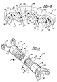
- Figure 1 is a perspective view of the subject invention;
- Figure 2 is a cross-sectional view taken along line 2-2 of Figure 1;
- Figure 3 is an enlarged view of the male and female members as shown in Figure 2;
- Figure 4 is a perspective view showing the male member in spaced relationship to the female member;
- Figure 5 is a cross-sectional view taken along line 5-5 of Figure 4;
- Figure 6 is a cross-sectional view taken along line 6-6 of Figure 4; and
- Figure 7 is a cross-sectional view taken along line 7-7 of Figure 4.
-
- A driveline assembly is generally shown at 10 in Figure 1. The
assembly 10 includes a tubularmale member 12 extending to ayoke 14. Theassembly 10 also includes a tubularfemale member 16 extending to ayoke 18. When assembled, thefemale member 16 slides over themale member 12 and an accordion shapedrubber boot 20 covers the interface between the male 12 and female 16 members to prevent the intrusion of water and/or dirt. - As can be seen in Figure 2, tubular
male member 12 has anaxis 22 with a thin wall defining inner 24 and outer 26 surfaces. Tubularfemale member 16 is disposed about theaxis 22 and has a thin wall defining inner 28 and outer 30 surfaces. - Referring to Figure 3, the thin wall of the
male member 12 presents circumferentially extending first generallylinear portions 32 disposed at a first radius r1 about theaxis 22. For purposes of this application, the radius of a linear portion is measured to a center of the linear portion. A male tooth, generally shown at 34, separates the next adjacent first generallylinear portions 32. Eachmale tooth 34 has a circumferentially extending second generallylinear portion 36 disposed at a second radius r2 about theaxis 22. The first radius r1 is larger than the second radius r2. Similarly, the thin wall of thefemale member 16 presents circumferentially extending third generallylinear portions 38 disposed at a third radius r3 about theaxis 22. A female tooth, generally shown at 40, separates the next adjacent third generallylinear portion 38. Eachfemale tooth 40 has a circumferentially extending fourth generallylinear portion 42 disposed at a fourth radius r4 about theaxis 22. The third r3 radius is larger than the fourth r4 radius. In the preferred embodiment, the first 32, second 36, third 38, and fourth 42 generally linear portions are linear. - Each
male tooth 34 includes a pair oflegs 44 extending radially from the secondlinear portion 36 to the firstlinear portion 32 and eachfemale tooth 40 includes a pair oflegs 46 extending radially from the fourthlinear portion 42 to the thirdlinear portion 38. Specifically, each male 34 and female 40 tooth projects inwardly from the first 32 and third 38 linear portions, respectively, toward theaxis 22. - The
legs teeth 34 of themale member 12 have a close tolerance fit with theteeth 40 of thefemale member 16 to minimize backlash from any transmission of torque. - In addition to the nonrotatable engagement, the
male member 12 slides within thefemale member 16 to permit relative longitudinal movement between the twomembers members male member 12 slides approximately 12.7 cm (five inches) within thefemale member 16 during assembly and disassembly and typically slides about one inch during typical driving operations. - An
elastomeric sleeve 48 is adhered to and conforms with theinner surface 28 of thefemale member 16 and is complementary in configuration to theouter surface 26 of themale member 12. Thesleeve 48 also adheres to a small portion of theouter surface 30 of thefemale member 16. Thesleeve 48 assists in filling any imperfections or gaps between the male 12 and female 16 members. Thelegs sleeve 48 for driving the male 12 and female 16 members. In other words, thesleeve 48 serves as a tooth size control and as a wear surface. As thefemale member 16 begins to rotate, the portion of thesleeve 48 covering thelegs 46 of thefemale member 16 engages thelegs 44 ofmale member 12. As discussed hereinbelow, thefemale member 16 is typically the drive shaft and themale member 12 is typically the driven shaft. - As can be seen in Figure 4,
male member 12 is an elongated tube having first 50 and second 52 ends with theyoke 14 fixedly secured tosecond end 52. Similarly thefemale member 16 is an elongated tube having first 54 and second 56 ends with theyoke 18 fixedly secured tosecond end 56. - The male 12 and female 16 members may be cut in length to any appropriate size for meeting desired specifications. Once sized, the
yokes members yokes yoke 18 of thefemale member 16 is connected to a coupling shaft (not shown) which in turn is connected to a transmission (not shown). Theyoke 14 of themale member 12 is in turn connected to a wheel axle (not shown). As discussed above, the male 12 and female 16 members are nonrotatably connected, which transmits rotational movement from the transmission to the wheel axle. - Figure 5 discloses a cross-sectional view through the first end 54 of the
female member 16 which clearly shows thesleeve 48 adhered to the inner 28 and outer 30 surfaces of thefemale member 16. As discussed in the background section, there is a degree of shrinkage when thesleeve 48 cools from an injection temperature to an operating or ambient temperature which allows themale member 12 to slide within thefemale member 16. - As best shown in the cross-sectional view of Figure 7, the first radius r1 differs in length from the second radius r2 a distance X which is less than 20% of the first radius r1. Similarly, and as shown in the cross-sectional view of Figure 6, the third radius r3 differs in length from the fourth radius r4 a distance Y which is less than 20% of the third radius r3. Accordingly, the
teeth - In one embodiment, the first radius r1 is 4.88 cm (1.9225 inches) and the second radius r2 is 4.39 cm (1.7295 inches) as measured from the center point of the first
linear portions 32 and the secondlinear portions 36, respectively. The distance X is 0.490 cm (0.193 inches) which equates to approximately 10% of the first radius r1. The third radius r3 is 5.44 cm (2.142 inches)and the fourth radius r4 is 4.95 cm (1.9505 inches) as measured from the center point of the thirdlinear portions 38 and the fourthlinear portions 42, respectively. The distance Y is 0.486 cm (0.1915 inches) which equates to approximately 9% of the third radius r3. - As also shown in Figures 6 and 7, the second 36 and third 38 linear portions are longer than the first 32 and fourth 42 linear portions. In other words, the linear portions or spaces between the teeth in the female member are longer than the teeth themselves. In fact, the second 36 and third 38 linear portions form more than 1/2 of the entire circumference respectively of the male 12 and female 16 members. Also, each female 40 tooth forms less than 1/20 of the entire circumference of the female 16 member. Specifically, each male 34 and female 40 tooth is located thirty degrees apart as referenced from the
axis 22 of the male 12 and female 16 members. This configuration of teeth and linear portions or spaces is very effective in transmitting high torque rotational forces from one member to another. - The invention has been described in an illustrative manner, and it is to be understood that the terminology which has been used is intended to be in the nature of words of description rather than of limitation.
- Obviously, many modifications and variations of the present invention are possible in light of the above teachings. It is, therefore, to be understood that within the scope of the appended claims the invention may be practiced otherwise than as specifically described.
Claims (9)
- A driveline assembly (10) comprising:a tubular male member (12) having an axis (22) with a thin wall defining inner (24) and outer (26) surfaces disposed about said axis (22) of said male member (12);a tubular female member (16) disposed about said axis (22) and having a thin wall defining inner (28) and outer (30) surfaces of said female member (16);a sleeve (48) adhered to one of said tubular male member (12) and said tubular female member (16), and conforming with said inner surface of said female member (16) and said outer surface of said male member (12) to fill any spaces between said tubular male member and said tubular female member;said male member (12) having first and second ends with a yoke (18) fixedly secured to said second end of said male member (12);said female member (16) having first and second ends with a yoke (18) fixedly secured to said second end of said female member (16);said thin wall of said male member (12) presenting circumferentially extending male teeth (34);said thin wall of said male member (12) also presenting circumferentially extending first generally linear portions (32) centered on a first radius (r1) about said axis (22) and said male teeth (34) separating adjacent first generally linear portions (32), each male tooth (34) having a circumferentially extending second generally linear portion (36) centered on a second radius (r2) about said axis (22);said thin wall of said female member (16) presenting circumferentially extending female teeth (40);said thin wall of said female member (16) also presenting circumferentially extending third generally linear portions (38) centered on a third radius (r3) about said axis (22) and said female teeth (40) separating adjacent third generally linear portions (38), each female tooth (40) having a circumferentially extending fourth generally linear portion (42) centered on a fourth radius (r4) about said axis (22); andsaid first radius (r1) being larger than said second radius (r2), said third radius (r3) being larger than said fourth radius (r4) and said second and third generally linear portions (36,38) having a greater circumferential length than the first and fourth generally linear portions (32,42) respectively,said driveline assembly (10) being characterised in that the difference in length between the hat and second radio (r1,r2) is less than 20% of the first radius (r1) and the difference in length between the third and fourth, radius (r3,r4) is less than 20% of the third radius (r3).
- An assembly (10) as set forth in Claim 1, wherein said sleeve (48) is adhered to said female tubular member (16).
- An assembly (10) as set forth in Claim 2 wherein said sleeve (48) is adhered to said inner surface of said female member (16) and is complementary in configuration to said outer surface of said male member (12) and said sleeve (48) also adheres to a portion of said outer surface of said female member (16).
- An assembly (10) as set forth in Claim 1 wherein said first, second, third, and fourth generally linear portions (32,36,38,42) are linear.
- An assembly (10) as set forth in Claim 4 wherein each male tooth (34) includes a pair of legs (44) extending radially from said second generally linear portion (36) to said first generally linear portion (32) and each female tooth (40) includes a pair of legs (46) extending radially from said fourth generally linear portion (42) to said third generally linear portion (38).
- An assembly (10) as set forth in Claim 5 wherein each male and female tooth (34,40) projects inwardly from said first and third generally linear portions (32,38), respectively, toward said axis (22).
- An assembly (10) as set forth in Claim 6 wherein said legs (44,46) of said male and female teeth (34,40) overlap in the radial direction for drivingly engaging said male and female members (12,16).
- The driveline assembly (10) of Claim 1, wherein the circumferential length of said second and third generally linear portions (36,38) comprise more than one half the entire circumference respectively of said male and female members.
- The driveline assembly (10) of Claim 1, wherein said male and female teeth (34,40) are located at an equal angle apart about said axis (22), said equal angle being 30 degrees.
Applications Claiming Priority (2)
| Application Number | Priority Date | Filing Date | Title |
|---|---|---|---|
| US08/899,532 US5951402A (en) | 1997-07-24 | 1997-07-24 | Driveline assembly |
| US899532 | 1997-07-24 |
Publications (2)
| Publication Number | Publication Date |
|---|---|
| EP0893613A1 EP0893613A1 (en) | 1999-01-27 |
| EP0893613B1 true EP0893613B1 (en) | 2004-10-06 |
Family
ID=25411155
Family Applications (1)
| Application Number | Title | Priority Date | Filing Date |
|---|---|---|---|
| EP98305575A Expired - Lifetime EP0893613B1 (en) | 1997-07-24 | 1998-07-14 | Cardan shaft |
Country Status (5)
| Country | Link |
|---|---|
| US (1) | US5951402A (en) |
| EP (1) | EP0893613B1 (en) |
| KR (1) | KR100278413B1 (en) |
| DE (1) | DE69826787T2 (en) |
| ES (1) | ES2234077T3 (en) |
Families Citing this family (18)
| Publication number | Priority date | Publication date | Assignee | Title |
|---|---|---|---|---|
| DE69922335T2 (en) | 1999-02-23 | 2005-12-15 | Matsui Universal Joint Corp. | Drive shaft and method for producing the same |
| US6279221B1 (en) * | 1999-09-08 | 2001-08-28 | Visteon Global Tech., Inc. | Vehicle driveshaft |
| US6949026B2 (en) | 2000-12-18 | 2005-09-27 | Timken Us Corporation | Axially compliant isolator |
| JP4869494B2 (en) * | 2001-05-15 | 2012-02-08 | 株式会社ミクニ | Bonding structure of resin intake manifold |
| US6565445B1 (en) | 2001-06-11 | 2003-05-20 | Auburn Clutch Co., Inc. | Torsional vibration dampening assembly |
| US6705949B2 (en) | 2001-08-27 | 2004-03-16 | Visteon Global Technologies, Inc. | Shaft spline having a straight side tooth profile |
| US6698076B2 (en) * | 2002-01-07 | 2004-03-02 | Meritor Heavy Vehicle Systems, Llc | Drive shaft manufacturing process |
| US6773199B2 (en) * | 2002-02-28 | 2004-08-10 | Gkn Walterscheid Gmbh | Coupling, especially torque limiting coupling |
| US7207890B2 (en) * | 2004-11-03 | 2007-04-24 | Cnh America Llc | Tubular telescoping drive shaft |
| US20060130309A1 (en) * | 2004-12-22 | 2006-06-22 | Torque-Traction Technologies, Inc. | Method of manufacturing a splined member having a coating of a material applied thereto |
| DE102005008920A1 (en) * | 2005-02-24 | 2006-09-14 | Wittenstein Ag | Coupling for connecting two components |
| US8230710B2 (en) * | 2005-03-25 | 2012-07-31 | American Axle & Manufacturing, Inc. | Method for forming a slip joint assembly with coated splines |
| GB2429761A (en) | 2005-09-03 | 2007-03-07 | Nsk Steering Sys Europ Ltd | Temperature accommodating vehicl steering column bush |
| DE102006032312A1 (en) | 2006-07-11 | 2008-01-24 | Bayerische Motoren Werke Ag | Torque transfer device |
| US20090215543A1 (en) * | 2008-02-25 | 2009-08-27 | American Axle & Manufacturing, Inc. | Slip yoke with internal splines having permanent coating and related method |
| US9309928B2 (en) | 2010-08-04 | 2016-04-12 | Arvinmeritor Technology, Llc | Yoke with stiffness ring |
| DE102010039253B4 (en) * | 2010-08-12 | 2023-09-28 | Zf Automotive Germany Gmbh | Telescopic vehicle steering shaft with vibration damper |
| US9890808B2 (en) * | 2015-04-22 | 2018-02-13 | American Axle & Manufacturing, Inc. | Telescoping propshaft |
Citations (3)
| Publication number | Priority date | Publication date | Assignee | Title |
|---|---|---|---|---|
| US4125000A (en) * | 1976-12-14 | 1978-11-14 | Grob, Inc. | Telescopic tubular power transmitting unit |
| US4406641A (en) * | 1979-10-22 | 1983-09-27 | Nadella | Torque transmitting coupling |
| EP0707157A1 (en) * | 1994-10-13 | 1996-04-17 | Matsui Universal Joint Manufacturing Company | Propeller shaft and method for producing the same |
Family Cites Families (13)
| Publication number | Priority date | Publication date | Assignee | Title |
|---|---|---|---|---|
| US2072090A (en) * | 1935-10-10 | 1937-03-02 | Borg Warner | Double universal joint assembly |
| US3066503A (en) * | 1961-05-23 | 1962-12-04 | Gen Tire & Rubber Co | Formed tube coupling |
| US3383756A (en) * | 1965-11-26 | 1968-05-21 | Borg Warner | Method of making a slip joint |
| US4552544A (en) * | 1982-12-27 | 1985-11-12 | Dana Corporation | Drive line slip joint assembly |
| AT384405B (en) * | 1985-07-22 | 1987-11-10 | Supervis Ets | LENGTH-CHANGEABLE STEERING SPINDLE FOR STEERING DEVICES IN MOTOR VEHICLES |
| US4862976A (en) * | 1988-11-22 | 1989-09-05 | Sandvik Rock Tools, Inc. | Spline drive for percussion drilling tool |
| US5243874A (en) * | 1992-02-24 | 1993-09-14 | Pittsburgh Tubular Shafting, Inc. | Method and apparatus for telescopically assembling a pair of elongated members |
| US5460574A (en) * | 1993-08-31 | 1995-10-24 | Trw Inc. | Variable length shaft assembly with a lash bushing |
| DE4329735A1 (en) * | 1993-09-03 | 1995-03-09 | Daimler Benz Ag | Steering spindle for a motor vehicle and method for the production thereof |
| DE4427532C2 (en) * | 1993-09-16 | 1998-07-23 | Walterscheid Gmbh Gkn | Length compensation with two profiles for drive shafts |
| DE19515103C2 (en) * | 1995-04-25 | 1997-07-03 | Freudenberg Carl Fa | Multi-spline connection |
| IT1278696B1 (en) * | 1995-06-07 | 1997-11-27 | Edi Bondioli | TUBULAR COMPONENT FOR TELESCOPIC TRANSMISSION SHAFTS |
| FR2749258B1 (en) * | 1996-05-30 | 1998-08-21 | Ecia Equip Composants Ind Auto | TELESCOPIC STEERING SHAFT, IN PARTICULAR FOR A MOTOR VEHICLE |
-
1997
- 1997-07-24 US US08/899,532 patent/US5951402A/en not_active Expired - Fee Related
-
1998
- 1998-07-01 KR KR1019980026370A patent/KR100278413B1/en not_active Expired - Fee Related
- 1998-07-14 EP EP98305575A patent/EP0893613B1/en not_active Expired - Lifetime
- 1998-07-14 DE DE69826787T patent/DE69826787T2/en not_active Expired - Fee Related
- 1998-07-14 ES ES98305575T patent/ES2234077T3/en not_active Expired - Lifetime
Patent Citations (3)
| Publication number | Priority date | Publication date | Assignee | Title |
|---|---|---|---|---|
| US4125000A (en) * | 1976-12-14 | 1978-11-14 | Grob, Inc. | Telescopic tubular power transmitting unit |
| US4406641A (en) * | 1979-10-22 | 1983-09-27 | Nadella | Torque transmitting coupling |
| EP0707157A1 (en) * | 1994-10-13 | 1996-04-17 | Matsui Universal Joint Manufacturing Company | Propeller shaft and method for producing the same |
Also Published As
| Publication number | Publication date |
|---|---|
| KR19990013505A (en) | 1999-02-25 |
| KR100278413B1 (en) | 2001-03-02 |
| DE69826787D1 (en) | 2004-11-11 |
| ES2234077T3 (en) | 2005-06-16 |
| US5951402A (en) | 1999-09-14 |
| DE69826787T2 (en) | 2005-10-13 |
| EP0893613A1 (en) | 1999-01-27 |
Similar Documents
| Publication | Publication Date | Title |
|---|---|---|
| US5951402A (en) | Driveline assembly | |
| US4540385A (en) | Drive shaft assembly | |
| CA2084379C (en) | Driveline torque fuse | |
| US6582151B2 (en) | Driving axle assembly | |
| US5716276A (en) | Yoke shaft for a vehicular driveshaft assembly | |
| US5647683A (en) | Axle and tube yoke attachment | |
| US6761503B2 (en) | Splined member for use in a slip joint and method of manufacturing the same | |
| US6015350A (en) | Collapsible vehicle driveshaft | |
| US7896749B2 (en) | Direct torque flow connection with optimized ratios in attachment methods | |
| EP1479933A2 (en) | Rolling ball spline slip joint with helically shaped cage | |
| US4543011A (en) | Clutch for rigidly connecting coaxial parts of construction, especially for Cardan shafts | |
| US20090263181A1 (en) | Joint assembly with centering flange | |
| US6257798B1 (en) | Universal joint coupling | |
| US20040216298A1 (en) | Method of forming tubing around a tube seal in a vehicular driveshaft assembly | |
| US6634078B1 (en) | Method of manufacturing a splined member for use in a slip joint | |
| US7077753B2 (en) | Cross groove hybrid plunging constant velocity joint for a propshaft tuned for energy absorption | |
| US11441610B2 (en) | Quick connect assembly and retaining member for use therein | |
| US6158916A (en) | Universal joint connector | |
| US20030004001A1 (en) | Simplified driveline | |
| US7040991B2 (en) | Plunging constant velocity joint for a propshaft tuned for energy absorption | |
| EP0339207B1 (en) | Viscous fluid coupling | |
| US4568312A (en) | Profiled hub for drive shaft assembly | |
| CN111810548A (en) | Device for vibration decoupling of two shaft sections | |
| GB1566035A (en) | Drive shaft for a motor vehicle wheel | |
| JP2001082441A (en) | Drive shaft |
Legal Events
| Date | Code | Title | Description |
|---|---|---|---|
| PUAI | Public reference made under article 153(3) epc to a published international application that has entered the european phase |
Free format text: ORIGINAL CODE: 0009012 |
|
| AK | Designated contracting states |
Kind code of ref document: A1 Designated state(s): DE ES FR GB IT |
|
| AX | Request for extension of the european patent |
Free format text: AL;LT;LV;MK;RO;SI |
|
| 17P | Request for examination filed |
Effective date: 19990722 |
|
| AKX | Designation fees paid |
Free format text: DE ES FR GB IT |
|
| 17Q | First examination report despatched |
Effective date: 20010924 |
|
| GRAP | Despatch of communication of intention to grant a patent |
Free format text: ORIGINAL CODE: EPIDOSNIGR1 |
|
| GRAS | Grant fee paid |
Free format text: ORIGINAL CODE: EPIDOSNIGR3 |
|
| GRAA | (expected) grant |
Free format text: ORIGINAL CODE: 0009210 |
|
| AK | Designated contracting states |
Kind code of ref document: B1 Designated state(s): DE ES FR GB IT |
|
| REG | Reference to a national code |
Ref country code: GB Ref legal event code: FG4D |
|
| REF | Corresponds to: |
Ref document number: 69826787 Country of ref document: DE Date of ref document: 20041111 Kind code of ref document: P |
|
| REG | Reference to a national code |
Ref country code: ES Ref legal event code: FG2A Ref document number: 2234077 Country of ref document: ES Kind code of ref document: T3 |
|
| PGFP | Annual fee paid to national office [announced via postgrant information from national office to epo] |
Ref country code: GB Payment date: 20050706 Year of fee payment: 8 |
|
| PGFP | Annual fee paid to national office [announced via postgrant information from national office to epo] |
Ref country code: FR Payment date: 20050708 Year of fee payment: 8 |
|
| PGFP | Annual fee paid to national office [announced via postgrant information from national office to epo] |
Ref country code: ES Payment date: 20050727 Year of fee payment: 8 |
|
| ET | Fr: translation filed | ||
| PLBE | No opposition filed within time limit |
Free format text: ORIGINAL CODE: 0009261 |
|
| STAA | Information on the status of an ep patent application or granted ep patent |
Free format text: STATUS: NO OPPOSITION FILED WITHIN TIME LIMIT |
|
| 26N | No opposition filed |
Effective date: 20050707 |
|
| PG25 | Lapsed in a contracting state [announced via postgrant information from national office to epo] |
Ref country code: GB Free format text: LAPSE BECAUSE OF NON-PAYMENT OF DUE FEES Effective date: 20060714 |
|
| PGFP | Annual fee paid to national office [announced via postgrant information from national office to epo] |
Ref country code: IT Payment date: 20060731 Year of fee payment: 9 |
|
| PGFP | Annual fee paid to national office [announced via postgrant information from national office to epo] |
Ref country code: DE Payment date: 20070131 Year of fee payment: 9 |
|
| GBPC | Gb: european patent ceased through non-payment of renewal fee |
Effective date: 20060714 |
|
| REG | Reference to a national code |
Ref country code: FR Ref legal event code: ST Effective date: 20070330 |
|
| REG | Reference to a national code |
Ref country code: ES Ref legal event code: FD2A Effective date: 20060715 |
|
| PG25 | Lapsed in a contracting state [announced via postgrant information from national office to epo] |
Ref country code: ES Free format text: LAPSE BECAUSE OF NON-PAYMENT OF DUE FEES Effective date: 20060715 |
|
| PG25 | Lapsed in a contracting state [announced via postgrant information from national office to epo] |
Ref country code: FR Free format text: LAPSE BECAUSE OF NON-PAYMENT OF DUE FEES Effective date: 20060731 Ref country code: DE Free format text: LAPSE BECAUSE OF NON-PAYMENT OF DUE FEES Effective date: 20080201 |
|
| PG25 | Lapsed in a contracting state [announced via postgrant information from national office to epo] |
Ref country code: IT Free format text: LAPSE BECAUSE OF NON-PAYMENT OF DUE FEES Effective date: 20070714 |