BACKGROUND OF THE INVENTION
The present invention relates to a color mixture prevention
technique for an ink-jet printing apparatus that ejects ink
droplets of differently colors through a plurality of nozzle
opening arrays to provide color printing.
An ink-jet printing apparatus for color printing is so
designed that an ink-jet head having a plurality of nozzle opening
arrays, generally four or more arrays, through which ink droplets
of different colors independently eject is mounted on a carriage.
The ink-jet printing apparatus repeats the following processing:
while the recording head is moving in the main scanning direction,
ink droplets corresponding to print data are ejected, and when the
data for one scanning is completed, the print position is shifted
a distance equivalent to a predetermined pitch.
Since the color printing quality is greatly affected by
the accuracy at which individual dots that constitute pixels are
positioned, in the printing apparatus, nozzle openings 2 of each
nozzle opening array, through which ink droplets are at least
ejected during color printing, are aligned for individual colors
along the same scanning lines, as is shown in Fig. 10A, so that
a relative accuracy for the positioning of dots that are formed
on a recording medium is ensured.
However, since dots of different colors are printed during
color printing, the individual ink colors tend to be mixed together.
To resolve this problem, Japanese Unexamined Patent
Publication No. Hei 4-118250 proposes a printing method, for an
ink-jet printing apparatus, as disclosed in Fig. 10B, whereby
nozzle opening arrays C, M, Y and K are shifted so there is one
print-pitch between them and so there are four print-pitches
between their nozzle openings 2, through which different color ink
droplets are ejected, and whereby, during one main scan, to prevent
the color-mixing of dots of different colors are not formed on the
same line at the same timing.
However, since during the course of one scan dots that form
one line contact dots in an adjacent line, some color-mixing occurs,
and two paper feeding types are required: paper feeding for
forming on each print line dots having different colors, and paper
feeding by which a printing area is changed by advancing the paper
a distance that is equivalent to the printing height of the
recording head. Therefore, a paper feeding distance error is
varied that cause banding and blank areas, and as a result, an
improvement in print quality can not be expected.
SUMMARY OF THE INVENTION
To resolve such shortcomings, it is one objective of the
present invention to provide an ink-jet printing apparatus that
does not cause banding or produce blank areas, and that high quality
color printing can be performed by preventing the mixing of
different colors.
The foregoing and other objects can be achieved by a
provision of an ink-jet printing apparatus which, according to the
present invention, includes an ink-jet recording head which moves
in a main scanning direction, the recording head having a plurality
of nozzle opening arrays, through which different color ink
droplets are independently ejected, are arranged in the main
scanning direction, and that feeds a recording medium in a
sub-scanning direction when one scan is completed, wherein the
recording head is so designed that a plurality of nozzle openings
for each of the nozzle opening arrays are arranged at intervals
of at least four or more print-pitches in the sub-scanning direction,
that the nozzle opening arrays are divided into at least two groups,
that the nozzle opening arrays belonging to each of the groups are
positioned along the same line in the main scanning direction, and
that the groups are shifted away from each other at least two
print-pitches in the sub-scanning direction; and wherein the
recording head uses an interlaced system to print color data.
Dots of different groups do not contact each other before
the ink is completely dried, and when printing for one scan line
is completed, a recording medium is fed a number of print-pitches
that corresponds to the nozzle opening count, so that a paper
feeding distance error can be constant.
BRIEF DESCRIPTION OF THE DRAWINGS
Fig. 1 is a diagram illustrating an arrangement of nozzle
openings of an ink-jet recording head according to a first
embodiment of the present invention;
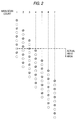
Fig. 2 is a diagram showing the printing form of the present
invention for each main scanning process.
Figs. 3A to 3E are diagrams showing a transient change until
the vertical and horizontal boundaries are formed between the first
group dots and the second group dots that are printed in the above
printing form;
Fig. 4 is a diagram illustrating an arrangement of nozzle
openings for a recording head according to a second embodiment of
the present invention;
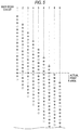
Fig. 5 is a diagram showing the printing form of the present
invention for each main scanning process;
Figs. 6A to 6I are diagrams showing a transient change until
the vertical and horizontal boundaries are formed between the first
to the fourth group dots that are printed in the above printing
form;
Figs. 7A and 7B are diagrams illustrating example
arrangements of nozzle openings of the recording head of the present
invention;
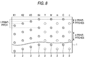
Fig. 8 is a diagram illustrating another arrangement of
nozzle openings for the recording head of the present invention;
Figs. 9A and 9B are diagrams illustrating additional
example arrangements of nozzle openings for the recording head the
present invention; and
Figs. 10A and 10B are diagrams illustrating arrangements
of nozzle openings for a conventional recording head.
DESCRIPTION OF THE PREFERRED EMBODIMENTS
The present invention will be described in detail during
the course of an explanation of the embodiments illustrated by the
drawings.
Fig. 1 shows an arrangement of nozzle opening arrays of
an ink-jet recording head according to a first embodiment of the
present invention. Reference symbols K, C, M and Y denote nozzle
opening arrays in a recording head 1 for independently ejecting
black, cyan, magenta and yellow ink droplets, respectively. The
nozzle opening arrays are arranged at the intervals equivalent to
the print-pitch count for the nozzle openings 2, i.e., an interval
of four print-pitches in this embodiment. In addition, the nozzle
openings 2, the number of which is a relative prime number to the
pitch count for the nozzle openings 2, five in this embodiment,
are aligned in the sub-scanning direction, i.e., in the paper
feeding direction.
For the arrays C, M and Y, the nozzle openings that eject
cyan, magenta and yellow ink droplets, respectively, are arranged
in rows that are shifted two print-pitches in sub-scanning
direction away from the nozzle opening array K that ejects black
ink droplets.
When the thus structured recording head 1 is moved at a
constant speed in the main scanning direction, i.e., in the
direction of the width of the recording medium, and at the same
time a drive signal is transmitted to pressure generation means,
such as a piezoelectric vibrator and a Joule heat generator that
are independently provided in a pressure generation chamber
communicating with the nozzle openings 2, during the first main
scanning, as is shown in Fig. 2, black dots (hatched circles ○
in Fig. 2) are printed in a line that extends in the main scanning
direction, and cyan, magenta and yellow dots (unhatched circles
○ in Fig. 2), the second group, are printed at a distance equivalent
to two print-pitches from the line formed by the black dots.
Therefore, during one scan, dots made with black ink, which
is the first group, do not contact dots made with other colored
inks, which belong to the second group, the mixing of the black
ink, which drastically affects the tones of the other colors when
it is mixed with them, with other colors can be completely prevented,
so that dots of cyan, magenta and yellow can be printed clearly.
Although the cyan, magenta and yellow dots are printed on the same
scan line, on the whole, the effect produced by mixing of these
ink colors is not critical, when compared with the deterioration
of image quality that occurs when the colors are mixed with black
ink.
When the printing for one scanning line is completed and
the recording medium is fed the number of print-pitches that
corresponds to the nozzle opening count, i.e., five print-pitches,
to repeat the printing in the same manner, dots of inks of the first
and the second groups are formed between the dots that were printed
at two print-pitch intervals during the first scan.
By the time the printing of the second scanning line is
initiated, the dots that were formed for the first scanning line
are dry, so that ink smudging occasioned by the formation of
succeeding dots not occur. Therefore, even when dots of colored
inks in the second group are formed adjacent to black dots that
were printed during the first scan, or when black dots are printed
adjacent to dots of colored inks in the second group that were
deposited during the first scan, even though the boundaries of the
dots are overlapped, the inks of the black dots and of the other
colored dots do not mix.
The printing is thereafter continued with the recording
medium being fed at constant five print-pitches, which is a number
equal to that of the nozzle openings in each nozzle opening array.
Since the paper feeding is performed at the constant pitch, a
constant paper feeding distance error can be maintained, and
printing without banding or blank areas can be provided.
With this printing method, at the boundaries indicated by
the crossed lines shown in Fig. 3A to 3E, the dots printed with
black ink, which constitutes the first group, do not contact dots
printed with other colored inks, which constitute the second group,
until a period of time equivalent to at least one scan period has
elapsed. Thus, the mixing of the ink in black dots with the inks
of the other colored dots does not occur along the vertical boundary
and the horizontal boundary (S in Figs. 3A to 3E denotes the number
of scans).
Fig. 4 shows the arrangement for the nozzle opening arrays
of an ink-jet printing apparatus according to a second embodiment
of the present invention. Reference symbols K, C, M and Y denote
arrays of nozzle opening in a recording head 1 that independently
eject black, cyan, magenta and yellow ink droplets. The nozzle
opening arrays are arranged at intervals equivalent in number to
the print-pitches used for arranging the nozzle openings 2,
intervals of eight print-pitches in this embodiment. And the
nozzle openings 2, the number of which is a relative prime number,
8 in this embodiment, to the print-pitch count used for arranging
the nozzle openings 2, i.e., five nozzle openings 2, are so arranged
that they are shifted two print-pitches away from each other in
the sub-scanning direction.
When the printing is initiated while the thus structured
recording head 1 is being moved, by a carriage, at a constant speed
in the main scanning direction, as is shown in Fig. 5, at the first
main scanning, black dots (hatched ○s in Fig. 5) that belong to
a first group, cyan dots (⊗s) that belong to a second group, magenta
dots (o ○s) that belong to a third group and yellow dots (○s) that
belong to a fourth group are printed along lines that are separated
from each other by two print-pitches in the sub-scanning direction.
As a result, the mixing of the colored inks, to include
black, can be completely prevented, and color ink dots can be
printed clearly.
When the printing for one scanning line is completed and
the recording medium is fed the number of print-pitches that
corresponds to the nozzle opening count, i.e., five print-pitches,
to repeat the printing in the same manner using the interlaced
method, dots are formed between the dots that were printed at two
print-pitch intervals during the first scan.
By the time the printing of the second scanning line is
initiated, the dots that were formed for the first scanning line
are so dry that ink is not smudged when it is contacted by the dots
that are printed next. Therefore, when dots of individual colored
inks are formed adjacent to dots that were printed during the first
scan, even though the boundaries of the dots partially overlap,
mixing of the colored inks does not occur.
The printing is thereafter continued while the recording
medium is fed by constant five print-pitches, a count that is equal
to that of the nozzle openings. Since the paper feeding is
performed at a constant print-pitch, a paper feeding distance error
can be constant, and printing without banding or the production
of blank areas can be provided.
With this printing method, at the boundaries indicated by
the crossed lines shown in Figs. 6A to 6I, since the colored ink
dots contact others only after one scan period has elapsed, no
mixing of the ink in the black dots and the ink in the other colored
dots occurs along the vertical boundary and the horizontal boundary
(S in Fig. 6 denotes the number of scans).
Figs. 7A and 7B show a third embodiment of the present
invention that is appropriate for six-color printing using dark
and light colored inks. Reference symbols K, C, M and Y denote
arrays of nozzle openings in a recording head 1 that independently
eject black, dark cyan, dark magenta and yellow ink droplets.
Reference symbols c and m denote arrays of nozzle openings in the
recording head 1 that independently eject light cyan and light
magenta ink droplets. In this embodiment, the nozzle opening
arrays are arranged at intervals of four print-pitches, and nozzle
openings 2, the number of which is a relative prime number to the
pitch count for the nozzle opening arrangement, 63 in this
embodiment, are arranged in the sub-scanning direction.
The arrays K, C, M and Y, of the nozzle openings that
respectively eject black, dark cyan, dark magenta and yellow ink
droplets, constitute the first group, and the arrays c and m, of
the nozzle openings that respectively eject light cyan and light
magenta ink droplets, constitute the second group. The nozzle
openings of the individual arrays of the first and the second groups
are shifted two print-pitches in the sub-scanning direction.
In this embodiment, as well as in the first embodiment,
when printing is initiated as the recording head 1 is being moved,
by the carriage, at a constant speed in the main scanning direction,
during the first main scan the dots (hatched ○s in Fig. 7) are
formed along individual lines using black, dark cyan, dark magenta
and yellow ink droplets, and dots (○s) for the light cyan and light
magenta colors, which belong to the second group, are separately
printed two print-pitches away from the dot line formed by the first
group.
As a result, the mixing of the inks used for dark cyan,
dark magenta and yellow dots with light cyan and light magenta dots
can be completely prevented, and light cyan and light magenta dots
that contribute greatly to the enhancement of the color tones can
be printed clearly. Although the light cyan and light magenta dots
are printed on the same line, the image quality is very little
affected by a change in color, when compared with when these inks
are mixed with a black, dark cyan, dark magenta or yellow ink that
has a high color density.
When printing for one scan line is completed and the
recording medium then is fed by the number of print-pitches
corresponding to that of the nozzle openings, i.e., 63 print-pitches,
to repeat the printing using the interlaced system, dots
are formed between the dots that were printed at two print-pitch
intervals during the first scan.
By the time the printing of the second scanning line is
initiated, the dots that were formed for the first scanning line
are dry, and there is no smudging of the ink used to print the dots.
Therefore, when dots printed with the light inks of the second
group are placed adjacent to dots printed with the dark inks of
the first group during the first scan, or when dots of dark ink
are placed adjacent to dots printed with light ink during the first
scan, even though the boundaries of dots are overlapped, the mixing
of colors does not occur, and the light inks used for dots are not
mixed with the dark colored inks.
Since the printing is performed while the recording medium
is being fed by constant 63 print-pitches that correspond in number
to nozzle openings, a constant 63 print-pitch paper feeding is
ensured, a constant paper feeding distance error can be maintained,
and printing can be performed without causing banding or producing
blank areas at the boundaries of a single scanning area.
With this printing method, as for the boundaries indicated
by cross lines as well as shown in Fig. 3, since the dark color
ink dots (corresponding to hatched ○ in Fig. 3) of the first group
contact the light ink dots (corresponding to ○ in Fig. 3) of the
second group after at least the one scanning period has elapsed,
the mixing of the light ink dots and the dark ink dots does not
occur along the vertical boundary and the horizontal boundary.
In the above embodiment, an explanation will be given in
order to prevent the mixture of black, dark cyan, dark magenta and
yellow ink dots with light cyan and light magenta ink dots. To
prevent the mixture of black, dark cyan, dark magenta ink dots with
light cyan, light magenta and yellow dots, as is shown in Fig. 7B,
the nozzle opening arrays K, M and C that eject dark color inks
of black, dark magenta and dark cyan constitute the first group,
and nozzle opening arrays Y, m and c that eject light color inks
of yellow, light magenta and light cyan constitute the second group.
Further, the nozzle openings 2 of each nozzle opening array are
formed by four print-pitches and the first group nozzle opening
arrays are shifted from the second group nozzle opening arrays by
two print-pitches. Therefore, in the same manner as previously
described, the mixing of the inks used for the black, dark magenta
and dark cyan dots with the inks used for the light cyan, light
magenta and yellow dots can be prevented.
In the above embodiment, the nozzle openings 2 through
which the individually colored inks are ejected are arranged at
the same print-pitches. However, when text data are the main print
data, as with a recording device used for clerical work, as is shown
in Fig. 8 a plurality of nozzle opening arrays K1, K2, K3 and K4,
which have nozzle openings arranged at constant print-pitches for
the ejection of black ink droplets, are shifted away from each other
one print-pitch in the sub-scanning direction. For text printing,
all the nozzle opening arrays K1, K2, K3 and K4 are employed. For
color printing, nozzle opening arrays for ejecting dark colored
ink, i.e., nozzle opening arrays M, C and K4 in this embodiment,
and nozzle opening arrays Y, m and c for ejecting light colored
ink are employed to print text at a high dot density in order to
ensure a high printing quality and a high printing speed. In
addition, high quality printing of color data can be performed
without light colored inks mixing with dark colored inks.
As is described above, since the colored inks are sorted
into a plurality of groups and nozzle opening arrays are shifted
two or more pitches, ink smudging can be substantially prevented.
However, the order of ejection of ink droplets of different groups
can not be taken into consideration.
That is, in the example in Fig. 5, rasters for dots
respectively represented by hatched ○, ⊗, o ○ and ○ are scanned for
printing. However, for one raster, dots represented by the hatched
○ are printed first, and for the other rasters, dots represented
by ⊗, o ○ or○ are printed first.
Although the ink smudging at the color boundary can be
prevented as previously described, when different ink colored dots
are to be formed and overlapped at the same position to express
a specific color (for example, when a green dot is formed by
overlapping a cyan C dot and a yellow Y dot), the compositions of
these inks differ, so that in the actual printing the hue (the color
tone) and the particle appearance are changed depending on which
ink dots are formed first (for expressing green dots, there is a
method for forming cyan dots first and then yellow dots, or a method
for forming yellow dots first and then cyan dots).
For this reason, in consonance with the background on which
to print colored inks and the combination of color inks, nozzle
openings of different colored inks must be arranged in the same
group to always form dots in the same order.
In Fig. 9A shows an example handling such a problem. Light
cyan, dark cyan, black, light magenta, dark magenta and yellow
nozzle opening arrays c, C, K, m, M and Y are located in the named
order. The light cyan nozzle opening array c and the dark cyan
nozzle opening array C are shifted away from each other three
print-pitches, the black nozzle opening array K and the light
magenta nozzle opening array m are shifted away from each other
three print-pitches, and the dark magenta nozzle opening array M
and the yellow nozzle opening array Y are shifted away from each
other three print-pitches.
In this example, the cyan and yellow nozzle openings are
located as the same group and the cyan dots are printed first.
Furthermore, the magenta and light cyan nozzle openings are located
as the same group and the light cyan dots are printed first. As
a result, an increase in the particle appearance due to smudging
is prevented, and black and yellow colors that tend to smudge are
arranged as different groups to completely prevent them from being
mixed.
In the example shown in Fig. 9B, light magenta, dark cyan,
black, light cyan, dark magenta and yellow nozzle opening arrays
m, C, K, c, M and Y are arranged in the named order. And the light
magenta nozzle opening array m and the dark cyan nozzle opening
array C are shifted away from each other three print-pitches, the
black nozzle opening array K and the light cyan nozzle opening array
c are shifted away from each other three print-pitches, and the
dark magenta nozzle opening array M and the yellow nozzle opening
array Y are shifted each other by three print-pitches.
In this example, since the cyan, light cyan and yellow
nozzle openings are located as the same group and the cyan and light
cyan dots are printed first, so that the increase in the particle
appearance due to smudging can be prevented, and black and yellow
colors that tend to smudge are arranged as different groups to
prevent them from being mixed.
As is described above, according to the present invention,
the recording head is so designed that a plurality of nozzle
openings for each of the nozzle opening arrays are arranged at
intervals of at least four or more print-pitches in the sub-scanning
direction, that the nozzle opening arrays are divided into at least
two groups, that the nozzle opening arrays belonging to each of
the groups are positioned along the same line in the main scanning
direction, and that the groups are shifted away from each other
at least two print-pitches in the sub-scanning direction, and thus,
color data can be printed by an interlace system. Therefore, a
recording medium can be fed at a constant distance, and ink dots
whose colors may be changed due to color mixing can be printed at
a time interval long enough to dry the ink, so that the mixing of
colors, banding or the production blank areas can be prevented
during printing, and high quality color printing can be provided.