EP0893143B1 - Load selector, in particular for exercise machine - Google Patents
Load selector, in particular for exercise machine Download PDFInfo
- Publication number
- EP0893143B1 EP0893143B1 EP98830398A EP98830398A EP0893143B1 EP 0893143 B1 EP0893143 B1 EP 0893143B1 EP 98830398 A EP98830398 A EP 98830398A EP 98830398 A EP98830398 A EP 98830398A EP 0893143 B1 EP0893143 B1 EP 0893143B1
- Authority
- EP
- European Patent Office
- Prior art keywords
- rod
- elements
- load
- weight
- load selector
- Prior art date
- Legal status (The legal status is an assumption and is not a legal conclusion. Google has not performed a legal analysis and makes no representation as to the accuracy of the status listed.)
- Expired - Lifetime
Links
Images


Classifications
-
- A—HUMAN NECESSITIES
- A63—SPORTS; GAMES; AMUSEMENTS
- A63B—APPARATUS FOR PHYSICAL TRAINING, GYMNASTICS, SWIMMING, CLIMBING, OR FENCING; BALL GAMES; TRAINING EQUIPMENT
- A63B21/00—Exercising apparatus for developing or strengthening the muscles or joints of the body by working against a counterforce, with or without measuring devices
- A63B21/06—User-manipulated weights
- A63B21/062—User-manipulated weights including guide for vertical or non-vertical weights or array of weights to move against gravity forces
- A63B21/0626—User-manipulated weights including guide for vertical or non-vertical weights or array of weights to move against gravity forces with substantially vertical guiding means
- A63B21/0628—User-manipulated weights including guide for vertical or non-vertical weights or array of weights to move against gravity forces with substantially vertical guiding means for vertical array of weights
-
- A—HUMAN NECESSITIES
- A63—SPORTS; GAMES; AMUSEMENTS
- A63B—APPARATUS FOR PHYSICAL TRAINING, GYMNASTICS, SWIMMING, CLIMBING, OR FENCING; BALL GAMES; TRAINING EQUIPMENT
- A63B21/00—Exercising apparatus for developing or strengthening the muscles or joints of the body by working against a counterforce, with or without measuring devices
- A63B21/06—User-manipulated weights
- A63B21/062—User-manipulated weights including guide for vertical or non-vertical weights or array of weights to move against gravity forces
- A63B21/0626—User-manipulated weights including guide for vertical or non-vertical weights or array of weights to move against gravity forces with substantially vertical guiding means
- A63B21/0628—User-manipulated weights including guide for vertical or non-vertical weights or array of weights to move against gravity forces with substantially vertical guiding means for vertical array of weights
- A63B21/063—Weight selecting means
Definitions
- the present invention relates to a load selector, in particular for an exercise machine that allows a variation of the resistance offered to the user thanks to a corresponding variation of the load related to a certain exercise.
- Numerous physical fitness or rehabilitation exercises entail the use of a load to provide a reaction to the force imparted by the user.
- Such machines comprise a base frame whereto are associated means for the user to impart a force, such as a bar, handles or oar-shaped levers, connected to a load which provides a resistance to the imparted force.
- the load gravitational, is defined by the weight of a series of brick- or disk-shaped weights, able to be placed in different mutual association according to the exercise to be performed until reaching the desired weight value.
- the connection between the means for imparting the force and the load is constituted by a cable or by a chain wound around transmission pulleys or through a lever system directly associated to the load and to the means for imparting the force.
- an exercise machine comprises a metal structure provided with a seat for the user (when necessary, of course) and a vertical guide destined to allow sliding by a series of weights connected, through the aforesaid chain or cable, to a bar (or other element for the application of force) which is gripped by the user to perform work generated by lifting the weights, thereby sliding them along the guide.
- a drawback of the machine currently in use derives from the ways whereby the working load is determined, i.e. by the manner in which the weights are associated to the chain or to the cable.
- Each weight can slide along the aforesaid vertical guide and it presents at least one vertical through hole and one horizontal through hole mutually intersecting; the superposition of the weights determines, in correspondence with the vertical holes, a sliding channel for a connecting rod positioned vertically and connected, in its upper end, to the chain; the selection of the load for the exercise to be performed is made manually by inserting a locking pin, passing through one of the horizontal holes presented by the weights, into one of the seats provided on the rod at different heights corresponding to the thickness of the weights. In this manner, all the weights located above the inserted pin are associated to the rod, and hence to the chain; by varying the insertion height, the number of weights associated to the chain and, hence, the load for the exercise is varied.
- US Patent 4.834.365 is related to a combined system of weights, with which it is possible to select, for the same weight stack, weights of different values.
- Patent 4.971.305 relates to a device that allows to adjust the weight stack on variable values, i.e. on values corresponding to sub-multiples of the unit of measure, with increments of small value. With the aforesaid solutions it is not possible to vary automatically (i.e. not manually) the reaction provided by the machine.
- US Patent 5.556.362 relates to a pin for weights able to disengage automatically when the weight stack reaches the rest position.
- the subject pin can be used to deselect one or more weight bars, but it is not usable to set the load of a given exercise or to increase the load itself.
- US Patent 4.610.449 relates to an automatic weight selector which automatically changes the selected weight after a set time interval.
- the patent describes a structure that fastens a plurality of bars to the tugging rod, through two pins, a lower one and an upper one, inserted in respective seats presented by two weight bars; load differentiation is allowed by a cam device commanded by a timer which, after a set period of time, extracts the lower pin to lighten the load, maintaining connected to the rod the above-lying bar and those above it.
- US Patents 4.746.113 and 5.350.344 relate to exercise machines wherein the load of the weight stack can be varied. Both documents teach the use of a structure able to be combined to a weight stack and supporting a series of pins movable horizontally between an engaged position wherein they are inserted in the related seats of the weight bars and a release position wherein they are retracted from the seats thereby freeing the weight bars. In practice, it is a sort of plate presenting pins facing the weight stack and able to be activated, by means of solenoids or electromagnetic actuators provided and acting upon each of the aforesaid pins. The solutions taught in the two patents provide for a structure which must follow the weight stack in its vertical stroke.
- US Patent 4.546.971 describes an exercise machine wherein the load of the weight stack can be varied through a lever positioned in proximity to the seat destined for the user.
- the weight bars used in this solution are fitted with a pin passing through the horizontal seat which allows access to the tugging rod of the weight stack.
- Each pin presents spring means which thrust it towards the outside of the weight bar, in a disengagement position from the tugging rod, and it is fitted with an outward projecting head
- the aforementioned lever is connected to a command rod able to slide vertically, provided with cams destined to interact with the heads presented by the pins, thereby thrusting the pins towards the tugging rod, in a number corresponding to the desired load value.
- the document US 5.306.221 refers to a weight adjusting device for muscle training machine comprising a rod presenting along its longitudinal development, cross sections of alternatively differentiated value in such a way as to define a series of notches or tapers, and fastening means comprising a plurality of coupling elements, positioned in correspondence with each of said weight elements, and movable between a first position wherein they do not interact with said rod and a second position wherein they interact with the rod itself, in correspondence with one of the notches or tapers, for the determination of the load.
- the object of the present invention therefore is to eliminate the aforementioned drawbacks with a load selector which allows to vary automatically the selection of the weights which define the load on an exercise machine.
- the load selector is usable, in particular, for an exercise machine wherein the load to be used in an exercise is variable and is determined by the value of the sum of a plurality of weight elements which are associated, through related fastening means, to a tugging element comprising a rod kinematically connected to appropriate means able to impart a force by a user, such weight elements being able to be stacked one on top of the other and presenting corresponding holed portions able to define a channel for said rod; the load selector comprising all the features expressed and claimed in claim 1.
- the subject selector 1 finds its application in those exercise machines wherein a gravitational load is provided, determined by the association of a plurality of weight elements to a tugging element connected to means for the execution of a force.
- the means for the execution of the force can comprise a bar, a handlebar, etc.; in the example, such means are indicated by the function block 41 in figure 1 and by a part of the exercise machine 5 shown in Figure 5 and comprising two pivoted arms. In Figure 5 the parts of the machine non strictly involved in the present invention have not been numbered.
- the means for the execution of a force 41 are connected through appropriate means 40, such as a cable or a chain, passing through a transmission pulley 42, to the related load provided on the exercise machine.
- the connecting means end in a tugging element constituted by a connection rod 4 which is connected to a plurality of weight elements 3 or bars to determine the load.
- the weight elements 3 present a pair of holes 32 which allow to stack the weight elements using rod shaped support organs 51, shown in Figure 51, and developing along the vertical axes indicated with dashed lines in Figure 3. On each weight element 3 is also provided a hole 30 through which the rod 4 can pass.
- a vertical channel comes to be defined through which the rod 4 can pass.
- the rod 4 presents, along its own longitudinal development, i.e. along the vertical direction, cross sections whose size is alternatively differentiated in such a way as to define a series of notches or tapers 45.
- the rod 4 presents a longitudinal profile shaped essentially as a saw tooth, i.e. it presents a conformation defined by a succession of truncated cones with the greater base 44 positioned at the top. This specific conformation is particularly advantageous in that it allows, as shall be explained farther on, the automatic association of the weight elements to the rod 4 itself.
- the weight elements 3 are associated to the rod 4 through fastening means which comprise a plurality of coupling elements 2, placed in correspondence with each of the weight elements 3.
- the coupling elements 3 which can comprise elements with laminar conformation, are movable between a first position wherein they do not interact with the rod 4 and a second position wherein they do interact with the rod 4 itself, in correspondence with one of the aforesaid notches or tapers 45.
- the coupling elements 2 are provided with a slotted portion 20 which is fitted onto the rod 4 and is able to interact therewith in correspondence with the activation of related drive means described here below.
- the drive means of the coupling means 2 are constituted by an element 6, movable parallel to the development of the rod 4.
- Such movable element 6 is constituted, in the embodiment shown, by a flexible belt contained and able to run within a guide structure 61, 62, 63 shaped as a "U" and extending to encompass the plurality of the weight elements 3.
- a guide with essentially rectangular open shape which follows its profile vertically on the two sides (61 and 62) and in the bottom portion 63 (shown with dashed line to highlight the belt 6 contained therein).
- the coupling element 2 presents the activation end 24 inserted at least partially into a first vertical portion 61 of the guide structure, in such a way as to be pushed by the flexible belt 6 when the latter is at a corresponding height.
- the coupling element 2 presents, on the opposite side with respect to the interaction end 24, a rod-shaped portion 21 whereon a spring 22 is fitted
- Such spring 22 is a possible embodiment of appropriate thrust means 22 presenting a reaction force R directed towards the first belt portion 61.
- the thrust means 22 maintain the coupling element 2 in contact with the rod 4; in particular, they maintain the slotted portion 20 in contact with one of the notches 45 of the rod 4 itself.
- the coupling element 2 is maintained stably in the engaged position wherein it associates the related weight 2 (and those positioned above it) to the rod 4.
- the belt 6 When the belt 6 reaches the corresponding height, it thrusts the related coupling element 2 in the direction indicated as F, removing the slotted portion from the rod 4.
- weight bar and related rod 4 In practice the engagement between weight bar and related rod 4 is determined solely by the action of the spring 22 and therefore all weight bars positioned above the vertical portion of the belt 6 shall be active, i.e. shall concur in the definition of the weight value.
- Figure 2 shows in its upper part a coupling element 2 associated with the related weight bar 3 similarly to a possible configuration for use, whilst, in its lower part, it shows another coupling element 2, disassociated from the related weight bar 3 and, therefore, in a configuration that could not be taken when in use.
- the latter For the association of the coupling elements 2 to the weight elements 3, the latter present a slot 31 partially travelled through by the rod-shaped portion 21 of the coupling element 2 and a seat 35 into which is inserted the distal end of the rod-shaped portion 21.
- a rivet 25 positioned vertically could also be provided, passing into a related slot 23 provided on the coupling element 2 and fastened in a related hole 36 of the weight element 3.
- the movement of the flexible belt 6 within the guide structure 61,62,63 can be allowed by motor means 65 constituted, for instance, by a gear motor, or manual activation means, such as a crank (not shown); in the case of motor drive, the latter can preferably be associated to electronic programming means such as those comprising a support of the "smart key" type.
- motor means 65 constituted, for instance, by a gear motor, or manual activation means, such as a crank (not shown); in the case of motor drive, the latter can preferably be associated to electronic programming means such as those comprising a support of the "smart key" type.
- two rollers 64 are provided around which, and externally to which, can pass the belt 6, moved by a driver roller 64', opposed to one of the previous ones, in order thereby to drive the belt 6 by friction.
- the flexible belt 6, in order to interact better with the interaction end 24 can present a rounded cross section.
Landscapes
- Health & Medical Sciences (AREA)
- Life Sciences & Earth Sciences (AREA)
- Biophysics (AREA)
- Orthopedic Medicine & Surgery (AREA)
- General Health & Medical Sciences (AREA)
- Physical Education & Sports Medicine (AREA)
- Rehabilitation Tools (AREA)
- Medicines Containing Plant Substances (AREA)
- Medicines Containing Material From Animals Or Micro-Organisms (AREA)
Description
- The present invention relates to a load selector, in particular for an exercise machine that allows a variation of the resistance offered to the user thanks to a corresponding variation of the load related to a certain exercise.
- Numerous physical fitness or rehabilitation exercises entail the use of a load to provide a reaction to the force imparted by the user.
- Currently, the implements constituting "traditional" weight training, such as dumb-bells, bars and the like, have been to a great extent replaced by exercise machines that are more complex and correlated to their use, indicated as isotonic machines.
- .Such machines comprise a base frame whereto are associated means for the user to impart a force, such as a bar, handles or oar-shaped levers, connected to a load which provides a resistance to the imparted force. The load, gravitational, is defined by the weight of a series of brick- or disk-shaped weights, able to be placed in different mutual association according to the exercise to be performed until reaching the desired weight value. The connection between the means for imparting the force and the load is constituted by a cable or by a chain wound around transmission pulleys or through a lever system directly associated to the load and to the means for imparting the force.
- In practice,according to the most widely used embodiment, an exercise machine comprises a metal structure provided with a seat for the user (when necessary, of course) and a vertical guide destined to allow sliding by a series of weights connected, through the aforesaid chain or cable, to a bar (or other element for the application of force) which is gripped by the user to perform work generated by lifting the weights, thereby sliding them along the guide.
- A drawback of the machine currently in use derives from the ways whereby the working load is determined, i.e. by the manner in which the weights are associated to the chain or to the cable. Each weight can slide along the aforesaid vertical guide and it presents at least one vertical through hole and one horizontal through hole mutually intersecting; the superposition of the weights determines, in correspondence with the vertical holes, a sliding channel for a connecting rod positioned vertically and connected, in its upper end, to the chain; the selection of the load for the exercise to be performed is made manually by inserting a locking pin, passing through one of the horizontal holes presented by the weights, into one of the seats provided on the rod at different heights corresponding to the thickness of the weights. In this manner, all the weights located above the inserted pin are associated to the rod, and hence to the chain; by varying the insertion height, the number of weights associated to the chain and, hence, the load for the exercise is varied.
- When, on the same machine, a series of exercises requiring different loads is to be performed (for instance, in passing from a series to the next one), or when the same machine is used by multiple persons alternating with different loads, it is necessary, for each change, to set the machine up, removing the locking pin and inserting it at a different height; such operation is found annoying, especially if one considers that gymnasium activities generally present a recreational and entertainment character.
- Amongst prior art solutions, US Patent 4.834.365 is related to a combined system of weights, with which it is possible to select, for the same weight stack, weights of different values.
- Patent 4.971.305 relates to a device that allows to adjust the weight stack on variable values, i.e. on values corresponding to sub-multiples of the unit of measure, with increments of small value. With the aforesaid solutions it is not possible to vary automatically (i.e. not manually) the reaction provided by the machine.
- US Patent 5.556.362 relates to a pin for weights able to disengage automatically when the weight stack reaches the rest position. The subject pin can be used to deselect one or more weight bars, but it is not usable to set the load of a given exercise or to increase the load itself.
- US Patent 4.610.449 relates to an automatic weight selector which automatically changes the selected weight after a set time interval. The patent describes a structure that fastens a plurality of bars to the tugging rod, through two pins, a lower one and an upper one, inserted in respective seats presented by two weight bars; load differentiation is allowed by a cam device commanded by a timer which, after a set period of time, extracts the lower pin to lighten the load, maintaining connected to the rod the above-lying bar and those above it. With the selector thus described it is therefore possible to change load by decreasing it and only once, in the course of a break.
- US Patents 4.746.113 and 5.350.344 relate to exercise machines wherein the load of the weight stack can be varied. Both documents teach the use of a structure able to be combined to a weight stack and supporting a series of pins movable horizontally between an engaged position wherein they are inserted in the related seats of the weight bars and a release position wherein they are retracted from the seats thereby freeing the weight bars. In practice, it is a sort of plate presenting pins facing the weight stack and able to be activated, by means of solenoids or electromagnetic actuators provided and acting upon each of the aforesaid pins. The solutions taught in the two patents provide for a structure which must follow the weight stack in its vertical stroke.
- US Patent 4.546.971 describes an exercise machine wherein the load of the weight stack can be varied through a lever positioned in proximity to the seat destined for the user. The weight bars used in this solution are fitted with a pin passing through the horizontal seat which allows access to the tugging rod of the weight stack. Each pin presents spring means which thrust it towards the outside of the weight bar, in a disengagement position from the tugging rod, and it is fitted with an outward projecting head The aforementioned lever is connected to a command rod able to slide vertically, provided with cams destined to interact with the heads presented by the pins, thereby thrusting the pins towards the tugging rod, in a number corresponding to the desired load value.
- The document US 5.306.221 refers to a weight adjusting device for muscle training machine comprising a rod presenting along its longitudinal development, cross sections of alternatively differentiated value in such a way as to define a series of notches or tapers, and fastening means comprising a plurality of coupling elements, positioned in correspondence with each of said weight elements, and movable between a first position wherein they do not interact with said rod and a second position wherein they interact with the rod itself, in correspondence with one of the notches or tapers, for the determination of the load.
- The object of the present invention therefore is to eliminate the aforementioned drawbacks with a load selector which allows to vary automatically the selection of the weights which define the load on an exercise machine.
- The load selector is usable, in particular, for an exercise machine wherein the load to be used in an exercise is variable and is determined by the value of the sum of a plurality of weight elements which are associated, through related fastening means, to a tugging element comprising a rod kinematically connected to appropriate means able to impart a force by a user, such weight elements being able to be stacked one on top of the other and presenting corresponding holed portions able to define a channel for said rod; the load selector comprising all the features expressed and claimed in
claim 1. - The technical features of the invention, according to the aforesaid objects, can be clearly seen from the content of the claims reported below and its advantages shall become more readily apparent in the detailed description that follows, made with reference to the accompanying drawings, which represent an embodiment provided purely by way of non limiting example, in which:
- Figure 1 shows a partial perspective and schematic view of a possible embodiment of the present invention, with a detail in plan view and in enlarged scale;
- Figure 2 shows, in a bottom perspective view, a detail of the embodiment as per Figure 1;
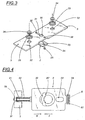
- Figure 3 shows, in a top perspective view, another detail of the embodiment shown in Figure 1;
- Figure 4 shows, in a partial top plan view, a detail of the embodiment as per Figure 1, shown, in part, in two possible operating configurations;
- Figure 5 shows, in an overall perspective view, an exercise machine with
variable load equipped with a load selector according to the present invention.
In the figures of the enclosed drawings, the
number 1 indicates an embodiment of a load selector according to the invention. - The
subject selector 1 finds its application in those exercise machines wherein a gravitational load is provided, determined by the association of a plurality of weight elements to a tugging element connected to means for the execution of a force. - In particular, with reference to the drawings which are only a non-limiting example thereof, the means for the execution of the force can comprise a bar, a handlebar, etc.; in the example, such means are indicated by the
function block 41 in figure 1 and by a part of theexercise machine 5 shown in Figure 5 and comprising two pivoted arms. In Figure 5 the parts of the machine non strictly involved in the present invention have not been numbered. - The means for the execution of a
force 41 are connected throughappropriate means 40, such as a cable or a chain, passing through atransmission pulley 42, to the related load provided on the exercise machine. - The connecting means end in a tugging element constituted by a
connection rod 4 which is connected to a plurality ofweight elements 3 or bars to determine the load. - The
weight elements 3 present a pair ofholes 32 which allow to stack the weight elements using rodshaped support organs 51, shown in Figure 51, and developing along the vertical axes indicated with dashed lines in Figure 3. On eachweight element 3 is also provided ahole 30 through which therod 4 can pass. - In practice, a vertical channel comes to be defined through which the
rod 4 can pass. - The
rod 4 presents, along its own longitudinal development, i.e. along the vertical direction, cross sections whose size is alternatively differentiated in such a way as to define a series of notches ortapers 45. - More in detail, the
rod 4 presents a longitudinal profile shaped essentially as a saw tooth, i.e. it presents a conformation defined by a succession of truncated cones with thegreater base 44 positioned at the top. This specific conformation is particularly advantageous in that it allows, as shall be explained farther on, the automatic association of the weight elements to therod 4 itself. - The
weight elements 3 are associated to therod 4 through fastening means which comprise a plurality ofcoupling elements 2, placed in correspondence with each of theweight elements 3. - The
coupling elements 3, which can comprise elements with laminar conformation, are movable between a first position wherein they do not interact with therod 4 and a second position wherein they do interact with therod 4 itself, in correspondence with one of the aforesaid notches ortapers 45. - The
coupling elements 2 are provided with a slottedportion 20 which is fitted onto therod 4 and is able to interact therewith in correspondence with the activation of related drive means described here below. - The drive means of the coupling means 2 are constituted by an
element 6, movable parallel to the development of therod 4. - Such
movable element 6 is constituted, in the embodiment shown, by a flexible belt contained and able to run within aguide structure weight elements 3. - In practice, around the weight stack is positioned a guide with essentially rectangular open shape which follows its profile vertically on the two sides (61 and 62) and in the bottom portion 63 (shown with dashed line to highlight the
belt 6 contained therein). - The
coupling element 2 presents theactivation end 24 inserted at least partially into a firstvertical portion 61 of the guide structure, in such a way as to be pushed by theflexible belt 6 when the latter is at a corresponding height. - The
coupling element 2, as better shown in Figure 4, presents, on the opposite side with respect to theinteraction end 24, a rod-shaped portion 21 whereon aspring 22 is fitted -
Such spring 22 is a possible embodiment of appropriate thrust means 22 presenting a reaction force R directed towards thefirst belt portion 61. The thrust means 22 maintain thecoupling element 2 in contact with therod 4; in particular, they maintain the slottedportion 20 in contact with one of thenotches 45 of therod 4 itself. - In other words, the
coupling element 2 is maintained stably in the engaged position wherein it associates the related weight 2 (and those positioned above it) to therod 4. When thebelt 6 reaches the corresponding height, it thrusts therelated coupling element 2 in the direction indicated as F, removing the slotted portion from therod 4. - In practice the engagement between weight bar and
related rod 4 is determined solely by the action of thespring 22 and therefore all weight bars positioned above the vertical portion of thebelt 6 shall be active, i.e. shall concur in the definition of the weight value. - Figure 2 shows in its upper part a
coupling element 2 associated with therelated weight bar 3 similarly to a possible configuration for use, whilst, in its lower part, it shows anothercoupling element 2, disassociated from therelated weight bar 3 and, therefore, in a configuration that could not be taken when in use. - For the association of the
coupling elements 2 to theweight elements 3, the latter present aslot 31 partially travelled through by the rod-shaped portion 21 of thecoupling element 2 and aseat 35 into which is inserted the distal end of the rod-shaped portion 21. - A
rivet 25 positioned vertically could also be provided, passing into arelated slot 23 provided on thecoupling element 2 and fastened in arelated hole 36 of theweight element 3. - The fact that the
coupling elements 2 are elastically maintained in engaged position in the absence of intervention by thebelt 6, and the particular saw-tooth conformation of therod 4 allow automatically to associate the weight elements to the rod even when the weight stack selected previously is in a raised position. This characteristic is particularly advantageous in that it allows the automatic mechanism that manages the program of the machine to select beforehand additional weight bars even when the athlete is in an active training phase; the subsequent lowering of therod 4 towards the motionless weight bars allows to "capture" automatically that or those weight bar(s) which in the meantime has or have already been selected by the movement of thebelt 6. This allows to gain time and not to have to interrupt an exercise or multiple series of exercises in order to set the machine differently. - The movement of the
flexible belt 6 within theguide structure - In the non limiting embodiment shown in Figure 1, two
rollers 64 are provided around which, and externally to which, can pass thebelt 6, moved by a driver roller 64', opposed to one of the previous ones, in order thereby to drive thebelt 6 by friction. These details have been shown only schematically. - Moreover, the
flexible belt 6, in order to interact better with theinteraction end 24 can present a rounded cross section. - The invention thus conceived can be subject to numerous modifications and variations, without thereby departing from the scope of the inventive concept. Moreover, all details can be replaced by technically equivalent elements.
Claims (9)
- Load selector for an exercise machine wherein the load to be used in an exercise is variable and is determined by the value of the sum of a plurality of weight elements which are associated, through related fastening means, to a tugging element comprising a rod kinematically connected to appropriate means able to exert a force by a user, said weight elements being able to be stacked on top of one another and presenting corresponding holed portions able to define a channel for said rod, said load selector comprising a rod (4) presenting, along its longitudinal development, i.e. along the direction of development of said channel, cross sections of alternatively differentiated value in such a way as to define a series of notches or tapers (45), and fastening means comprising a plurality of coupling elements (2), positioned in correspondence with each of said weight elements (3), and movable between a first position wherein they do not interact with said rod and a second position wherein they do interact with the rod (4) itself, in correspondence with one of said series of notches or tapers (45), for the determination of said load and being characterised in that it comprises means for moving said coupling means (2) comprising an element (6) movable parallel to the development of said rod (4) and in that said coupling means (2) comprise elements of essentially laminar development, coupled to each weight element and presenting an interactivation end (24) able to be thrust by said movable element (6).
- Load selector according to claim 1, characterised in that said rod (4) presents a longitudinal profile shaped essentially as a saw tooth.
- Load selector according to claim 1, characterised in that said rod (4) presents a conformation defined by a succession of truncated cones with the greater base (44) positioned at the top.
- Load selector according to claim 1, characterised in that said coupling elements comprise elements with laminar conformation (2), provided with a slotted portion (20) fitted onto said rod (4), and able to interact therewith in correspondence with the activation of related drive means.
- Load selector according to claim, 1 characterised in that said movable element (6) comprises a flexible belt contained and able to run within a guide structure (61, 62, 63) shaped as a "U" and extending to encompass said plurality of weight elements (3), and in that said deactivation end (24) is at least partially inserted in a first portion (61) of said guide structure, in such a way as to be thrust by said flexible belt (6) when the latter is at a corresponding height.
- Load selector according to claim 5, characterised in that, on each of said laminar elements (2) are provided thrust means (22) with reaction directed towards said first belt portion (61) able to maintain said slotted portion of said laminar elements in contact with said rod (4), i.e. able to maintain the laminar elements (2) in said first position.
- Load selector according to claim 5, characterised in that on said guide structure (61, 62, 63) are provided drive means (65) able to move said flexible belt (6) to run parallel to said weight elements.
- Load selector according to claim 7, characterised in that said drive means (65) comprise a drive roller (64') positioned along the path of said belt (6), opposite with respect to an idle roller (64).
- Load selector according to claim 5, characterised in that said flexible belt (6) presents a rounded cross section.
Applications Claiming Priority (2)
| Application Number | Priority Date | Filing Date | Title |
|---|---|---|---|
| ITBO970446 | 1997-07-22 | ||
| IT97BO000446A IT1293260B1 (en) | 1997-07-22 | 1997-07-22 | LOAD SELECTOR, IN PARTICULAR FOR GYMNUM MACHINE. |
Publications (3)
| Publication Number | Publication Date |
|---|---|
| EP0893143A2 EP0893143A2 (en) | 1999-01-27 |
| EP0893143A3 EP0893143A3 (en) | 1999-03-31 |
| EP0893143B1 true EP0893143B1 (en) | 2003-10-01 |
Family
ID=11342420
Family Applications (1)
| Application Number | Title | Priority Date | Filing Date |
|---|---|---|---|
| EP98830398A Expired - Lifetime EP0893143B1 (en) | 1997-07-22 | 1998-07-01 | Load selector, in particular for exercise machine |
Country Status (7)
| Country | Link |
|---|---|
| US (1) | US6174265B1 (en) |
| EP (1) | EP0893143B1 (en) |
| BR (1) | BR9802540A (en) |
| CA (1) | CA2243723A1 (en) |
| DE (1) | DE69818570T2 (en) |
| ES (1) | ES2207807T3 (en) |
| IT (1) | IT1293260B1 (en) |
Families Citing this family (49)
| Publication number | Priority date | Publication date | Assignee | Title |
|---|---|---|---|---|
| US6500106B1 (en) * | 1996-06-21 | 2002-12-31 | Kent Fulks | Method and apparatus for mechanical emulation of dumbbells |
| US6632161B1 (en) * | 2000-02-03 | 2003-10-14 | Daniel Nir | Apparatus and a method for loading weights |
| US6582345B2 (en) * | 2000-02-03 | 2003-06-24 | Normand Roy | Weight holder device for weight lifting apparatus |
| US6575882B2 (en) * | 2001-02-26 | 2003-06-10 | James Chen | Exercise device having weights and safety mechanism to maintain weights in place |
| RU2188686C1 (en) * | 2001-03-06 | 2002-09-10 | Синцов Александр Леонидович | Loading selector for muscle exercising mechanism |
| US7335139B2 (en) * | 2001-11-13 | 2008-02-26 | Cybex International, Inc. | Incremental weight system |
| US20030114276A1 (en) * | 2001-12-13 | 2003-06-19 | Schiff Jon D. | Weightlifting apparatus |
| JP4024245B2 (en) * | 2002-01-28 | 2007-12-19 | リ,ビョンドン | Weight adjustment device for weight training equipment |
| US7261678B2 (en) * | 2002-06-07 | 2007-08-28 | Nautilus, Inc. | Adjustable dumbbell system |
| RU2236882C1 (en) * | 2003-04-08 | 2004-09-27 | Шишонин Александр Юрьевич | Device for training and treating |
| US20050085351A1 (en) * | 2003-10-17 | 2005-04-21 | Robert Kissel | Exercise resistance |
| US8016725B2 (en) | 2003-10-17 | 2011-09-13 | Exertron, Llc | Variable resistance system |
| US7179208B1 (en) * | 2004-06-16 | 2007-02-20 | Mark Nalley | Weight plate with externally actuated internal locking device |
| US7736283B2 (en) * | 2006-10-04 | 2010-06-15 | Nautilus, Inc. | Exercise machine having rotatable weight selection index |
| US7740568B2 (en) * | 2004-10-04 | 2010-06-22 | Nautilus, Inc. | Exercise machine having rotatable weight selection index |
| US7507189B2 (en) | 2004-12-14 | 2009-03-24 | Nautilus, Inc. | Exercise weight stack apparatus |
| US7758478B2 (en) * | 2005-03-17 | 2010-07-20 | Nautilus, Inc. | Weight selection apparatus for a weight stack |
| USD542368S1 (en) * | 2005-06-03 | 2007-05-08 | Interspiro Ab | Diving weight |
| CN2930772Y (en) * | 2006-01-23 | 2007-08-08 | 锐铭运动用品(厦门)有限公司 | Adjustable dumbbell |
| BRPI0602697B1 (en) * | 2006-06-14 | 2018-06-12 | Nishimura Takashi | WEIGHT SELECTOR FOR MUSCLE APPARATUS |
| ITBO20060534A1 (en) * | 2006-07-11 | 2008-01-12 | Technogym Spa | GINNICA MACHINE. |
| EP2109484B1 (en) * | 2007-02-09 | 2021-03-17 | Core Health & Fitness Llc | Weight plate with externally actuated internal locking device |
| US20080242520A1 (en) * | 2007-03-28 | 2008-10-02 | Hubbard Adam P | Exercise apparatus, resistance selector for exercise apparatus and related methods |
| US7614981B2 (en) * | 2007-06-11 | 2009-11-10 | Guofang Cao | Weight selection system for fitness training equipment |
| US7708672B2 (en) * | 2007-12-20 | 2010-05-04 | Precor Incorporated | Incremental weight and selector |
| US7871357B2 (en) * | 2007-12-20 | 2011-01-18 | Precor Incorporated | Weight stack selector |
| US7815554B2 (en) * | 2007-12-20 | 2010-10-19 | Precor Incorporated | Weight stack selector |
| DE102008009399B4 (en) * | 2008-02-15 | 2009-12-03 | Reinbold Gmbh & Co. Kg | Device for training the muscles of the body |
| US8152702B2 (en) * | 2008-03-05 | 2012-04-10 | Icon Health & Fitness, Inc. | Exercise apparatus, resistance selector for exercise apparatus and related methods |
| EP2488262B1 (en) | 2009-10-16 | 2014-07-16 | Douglas Dorsay | Exercise device and method |
| US8568279B2 (en) | 2010-03-31 | 2013-10-29 | Nautilus, Inc. | Engagement interface for an exercise machine |
| US8876674B2 (en) | 2010-03-31 | 2014-11-04 | Nautilus, Inc. | Selectable weight stack |
| US8845498B2 (en) | 2010-03-31 | 2014-09-30 | Nautilus, Inc. | Lockout mechanism for a weight stack exercise machine |
| US9186537B2 (en) | 2013-01-03 | 2015-11-17 | Precor Incorporated | Incremental weight and selector |
| CN104884133B (en) | 2013-03-14 | 2018-02-23 | 艾肯运动与健康公司 | Force exercise equipment with flywheel |
| EP3974036B1 (en) | 2013-12-26 | 2024-06-19 | iFIT Inc. | Magnetic resistance mechanism in a cable machine |
| WO2015191445A1 (en) | 2014-06-09 | 2015-12-17 | Icon Health & Fitness, Inc. | Cable system incorporated into a treadmill |
| TWI644702B (en) | 2015-08-26 | 2018-12-21 | 美商愛康運動與健康公司 | Strength exercise mechanisms |
| US10940360B2 (en) | 2015-08-26 | 2021-03-09 | Icon Health & Fitness, Inc. | Strength exercise mechanisms |
| US10293211B2 (en) | 2016-03-18 | 2019-05-21 | Icon Health & Fitness, Inc. | Coordinated weight selection |
| US10441840B2 (en) | 2016-03-18 | 2019-10-15 | Icon Health & Fitness, Inc. | Collapsible strength exercise machine |
| US9731158B1 (en) * | 2016-04-28 | 2017-08-15 | Chiu-Hsiang Lo | Weight training assembly |
| US10252109B2 (en) | 2016-05-13 | 2019-04-09 | Icon Health & Fitness, Inc. | Weight platform treadmill |
| US10661114B2 (en) | 2016-11-01 | 2020-05-26 | Icon Health & Fitness, Inc. | Body weight lift mechanism on treadmill |
| US10933272B2 (en) | 2018-06-22 | 2021-03-02 | Glenn Polinsky | Auto-adjustable weight device, system, and method |
| CN109224371B (en) * | 2018-10-18 | 2020-12-04 | 安徽省华腾农业科技有限公司经开区分公司 | Physical training device |
| US10478657B1 (en) * | 2019-04-08 | 2019-11-19 | Matthew Demo | Weight lifting plate |
| US12070643B1 (en) * | 2023-08-09 | 2024-08-27 | Stack Bands, LLC | Supplemental resistance device for selectorized weight training machines |
| TWI859092B (en) * | 2024-03-20 | 2024-10-11 | 芙瑞實業股份有限公司 | An adjustment structure for fitness equipment |
Family Cites Families (15)
| Publication number | Priority date | Publication date | Assignee | Title |
|---|---|---|---|---|
| US90309A (en) * | 1869-05-18 | Improved washing-machine | ||
| US1053109A (en) * | 1910-12-08 | 1913-02-11 | Internat Gymnasium Supply Company | Wall exercising apparatus. |
| US3438627A (en) * | 1966-07-25 | 1969-04-15 | Fitness King Inc | Weight-lifting device |
| CH537741A (en) * | 1971-02-10 | 1973-06-15 | Chillier Maurice | Mechanotherapy device |
| US4546971A (en) * | 1984-09-05 | 1985-10-15 | Paul Raasoch | Exercise device |
| EP0177643A1 (en) * | 1984-10-09 | 1986-04-16 | Géraud Vitrac | Device with precise, silent and quick latching for selecting and damping dynamic efforts, especially designed for muscle strengthening and reeducation apparatuses |
| US4610449A (en) | 1985-08-26 | 1986-09-09 | Diercks Jr George F | Automatic weight selector |
| US4746113A (en) | 1987-02-24 | 1988-05-24 | Kissel Robert M | Automatically adjustable exercise equipment, and control system and method therefor |
| US4834365A (en) | 1987-06-11 | 1989-05-30 | Jones Arthur A | Compound weight system |
| US4971305A (en) | 1989-01-31 | 1990-11-20 | Rennex Brian G | Variable add-on weight device |
| US5306221A (en) * | 1992-12-15 | 1994-04-26 | Abe Itaru | Weight adjusting device for muscle training machine |
| US5350344A (en) | 1993-01-06 | 1994-09-27 | Kissel Robert M | Exercise machine |
| US5643151A (en) * | 1995-02-27 | 1997-07-01 | Naimo; Salvatore G. | Weight release mechanism for weight-lifting equipment |
| US5556362A (en) | 1995-03-20 | 1996-09-17 | Whipps; Allen M. | Automatic weight stack pin selector |
| IT1290159B1 (en) * | 1996-12-20 | 1998-10-19 | Newform S P A | DEVICE FOR THE SELECTION AND AUTOMATIC HOOKING OF WEIGHTS IN TOOLS FOR PHYSICAL EXERCISE. |
-
1997
- 1997-07-22 IT IT97BO000446A patent/IT1293260B1/en active IP Right Grant
-
1998
- 1998-07-01 DE DE69818570T patent/DE69818570T2/en not_active Expired - Lifetime
- 1998-07-01 EP EP98830398A patent/EP0893143B1/en not_active Expired - Lifetime
- 1998-07-01 ES ES98830398T patent/ES2207807T3/en not_active Expired - Lifetime
- 1998-07-20 CA CA002243723A patent/CA2243723A1/en not_active Abandoned
- 1998-07-21 BR BR9802540A patent/BR9802540A/en not_active IP Right Cessation
- 1998-07-22 US US09/120,233 patent/US6174265B1/en not_active Expired - Lifetime
Also Published As
| Publication number | Publication date |
|---|---|
| DE69818570D1 (en) | 2003-11-06 |
| ES2207807T3 (en) | 2004-06-01 |
| US6174265B1 (en) | 2001-01-16 |
| BR9802540A (en) | 1999-07-06 |
| DE69818570T2 (en) | 2004-08-05 |
| ITBO970446A1 (en) | 1999-01-22 |
| CA2243723A1 (en) | 1999-01-22 |
| IT1293260B1 (en) | 1999-02-16 |
| ITBO970446A0 (en) | 1997-07-22 |
| EP0893143A3 (en) | 1999-03-31 |
| EP0893143A2 (en) | 1999-01-27 |
Similar Documents
| Publication | Publication Date | Title |
|---|---|---|
| US6174265B1 (en) | Load selector, in particular for exercise machine | |
| EP1878472B1 (en) | Exercise machine | |
| US5556362A (en) | Automatic weight stack pin selector | |
| EP1804928B1 (en) | Exercise machine having rotatable weight selection index | |
| DE69412901T2 (en) | Exercise device and procedure | |
| US8016725B2 (en) | Variable resistance system | |
| US20050085351A1 (en) | Exercise resistance | |
| US5447480A (en) | Weight lifting machine | |
| US6991588B1 (en) | Standing single leg press exercise machine | |
| US8187155B2 (en) | Training machine | |
| US4195834A (en) | Vertical shoulder and lateral shoulder exercise machine | |
| US20150202485A1 (en) | Exercise machine for providing weight lifting exercises similar to those provided by a free weight barbell | |
| DE60310175T2 (en) | exerciser | |
| US9242134B2 (en) | Spring loaded weight stack selector pin | |
| US6896644B1 (en) | Weight stand for free weights | |
| US5046725A (en) | Variable weight grip exerciser | |
| US20220362621A1 (en) | Gymnastic Machine for Weightlifting | |
| KR100515686B1 (en) | Sporting goods for weight training | |
| EP3153215A2 (en) | Load adjustiment system for gymnastic machines and tensioning and returning device for said adjusting system | |
| US20090247367A1 (en) | Ultimate Workout Machine | |
| US20260034394A1 (en) | System and method for improving performance of traditional weight stack weightlifting machines | |
| WO1996037266A1 (en) | Weight lifting machine |
Legal Events
| Date | Code | Title | Description |
|---|---|---|---|
| PUAI | Public reference made under article 153(3) epc to a published international application that has entered the european phase |
Free format text: ORIGINAL CODE: 0009012 |
|
| AK | Designated contracting states |
Kind code of ref document: A2 Designated state(s): DE ES FR GB IT NL |
|
| AX | Request for extension of the european patent |
Free format text: AL;LT;LV;MK;RO;SI |
|
| PUAL | Search report despatched |
Free format text: ORIGINAL CODE: 0009013 |
|
| AK | Designated contracting states |
Kind code of ref document: A3 Designated state(s): AT BE CH CY DE DK ES FI FR GB GR IE IT LI LU MC NL PT SE |
|
| AX | Request for extension of the european patent |
Free format text: AL;LT;LV;MK;RO;SI |
|
| 17P | Request for examination filed |
Effective date: 19990511 |
|
| AKX | Designation fees paid |
Free format text: DE ES FR GB IT NL |
|
| 17Q | First examination report despatched |
Effective date: 20020809 |
|
| GRAH | Despatch of communication of intention to grant a patent |
Free format text: ORIGINAL CODE: EPIDOS IGRA |
|
| GRAH | Despatch of communication of intention to grant a patent |
Free format text: ORIGINAL CODE: EPIDOS IGRA |
|
| RAP1 | Party data changed (applicant data changed or rights of an application transferred) |
Owner name: TECHNOGYM S.P.A. |
|
| GRAA | (expected) grant |
Free format text: ORIGINAL CODE: 0009210 |
|
| AK | Designated contracting states |
Kind code of ref document: B1 Designated state(s): DE ES FR GB IT NL |
|
| REG | Reference to a national code |
Ref country code: GB Ref legal event code: FG4D |
|
| REF | Corresponds to: |
Ref document number: 69818570 Country of ref document: DE Date of ref document: 20031106 Kind code of ref document: P |
|
| REG | Reference to a national code |
Ref country code: ES Ref legal event code: FG2A Ref document number: 2207807 Country of ref document: ES Kind code of ref document: T3 |
|
| ET | Fr: translation filed | ||
| PLBE | No opposition filed within time limit |
Free format text: ORIGINAL CODE: 0009261 |
|
| STAA | Information on the status of an ep patent application or granted ep patent |
Free format text: STATUS: NO OPPOSITION FILED WITHIN TIME LIMIT |
|
| 26N | No opposition filed |
Effective date: 20040702 |
|
| PGFP | Annual fee paid to national office [announced via postgrant information from national office to epo] |
Ref country code: ES Payment date: 20130726 Year of fee payment: 16 Ref country code: NL Payment date: 20130726 Year of fee payment: 16 Ref country code: DE Payment date: 20130729 Year of fee payment: 16 |
|
| PGFP | Annual fee paid to national office [announced via postgrant information from national office to epo] |
Ref country code: GB Payment date: 20130729 Year of fee payment: 16 Ref country code: FR Payment date: 20130717 Year of fee payment: 16 |
|
| PGFP | Annual fee paid to national office [announced via postgrant information from national office to epo] |
Ref country code: IT Payment date: 20130725 Year of fee payment: 16 |
|
| REG | Reference to a national code |
Ref country code: DE Ref legal event code: R119 Ref document number: 69818570 Country of ref document: DE |
|
| REG | Reference to a national code |
Ref country code: NL Ref legal event code: V1 Effective date: 20150201 |
|
| GBPC | Gb: european patent ceased through non-payment of renewal fee |
Effective date: 20140701 |
|
| PG25 | Lapsed in a contracting state [announced via postgrant information from national office to epo] |
Ref country code: NL Free format text: LAPSE BECAUSE OF NON-PAYMENT OF DUE FEES Effective date: 20150201 |
|
| REG | Reference to a national code |
Ref country code: FR Ref legal event code: ST Effective date: 20150331 |
|
| PG25 | Lapsed in a contracting state [announced via postgrant information from national office to epo] |
Ref country code: IT Free format text: LAPSE BECAUSE OF NON-PAYMENT OF DUE FEES Effective date: 20140701 Ref country code: DE Free format text: LAPSE BECAUSE OF NON-PAYMENT OF DUE FEES Effective date: 20150203 |
|
| REG | Reference to a national code |
Ref country code: DE Ref legal event code: R119 Ref document number: 69818570 Country of ref document: DE Effective date: 20150203 |
|
| PG25 | Lapsed in a contracting state [announced via postgrant information from national office to epo] |
Ref country code: GB Free format text: LAPSE BECAUSE OF NON-PAYMENT OF DUE FEES Effective date: 20140701 Ref country code: FR Free format text: LAPSE BECAUSE OF NON-PAYMENT OF DUE FEES Effective date: 20140731 |
|
| REG | Reference to a national code |
Ref country code: ES Ref legal event code: FD2A Effective date: 20150827 |
|
| PG25 | Lapsed in a contracting state [announced via postgrant information from national office to epo] |
Ref country code: ES Free format text: LAPSE BECAUSE OF NON-PAYMENT OF DUE FEES Effective date: 20140702 |