EP0892984B1 - Magnet array for magnetrons - Google Patents
Magnet array for magnetrons Download PDFInfo
- Publication number
- EP0892984B1 EP0892984B1 EP97915568A EP97915568A EP0892984B1 EP 0892984 B1 EP0892984 B1 EP 0892984B1 EP 97915568 A EP97915568 A EP 97915568A EP 97915568 A EP97915568 A EP 97915568A EP 0892984 B1 EP0892984 B1 EP 0892984B1
- Authority
- EP
- European Patent Office
- Prior art keywords
- target
- magnets
- magnetron
- array
- magnet
- Prior art date
- Legal status (The legal status is an assumption and is not a legal conclusion. Google has not performed a legal analysis and makes no representation as to the accuracy of the status listed.)
- Expired - Lifetime
Links
Images

Classifications
-
- H—ELECTRICITY
- H01—ELECTRIC ELEMENTS
- H01J—ELECTRIC DISCHARGE TUBES OR DISCHARGE LAMPS
- H01J37/00—Discharge tubes with provision for introducing objects or material to be exposed to the discharge, e.g. for the purpose of examination or processing thereof
- H01J37/32—Gas-filled discharge tubes
- H01J37/34—Gas-filled discharge tubes operating with cathodic sputtering
- H01J37/3411—Constructional aspects of the reactor
- H01J37/345—Magnet arrangements in particular for cathodic sputtering apparatus
- H01J37/3452—Magnet distribution
-
- H—ELECTRICITY
- H01—ELECTRIC ELEMENTS
- H01J—ELECTRIC DISCHARGE TUBES OR DISCHARGE LAMPS
- H01J37/00—Discharge tubes with provision for introducing objects or material to be exposed to the discharge, e.g. for the purpose of examination or processing thereof
- H01J37/32—Gas-filled discharge tubes
- H01J37/34—Gas-filled discharge tubes operating with cathodic sputtering
- H01J37/3402—Gas-filled discharge tubes operating with cathodic sputtering using supplementary magnetic fields
- H01J37/3405—Magnetron sputtering
- H01J37/3408—Planar magnetron sputtering
Definitions
- the invention which is the subject of this application relates to improvements to the form and operation of magnetrons which can be operated for the sputter deposition of material from a target of said material when said magnetron is activated.
- the sputtering of material targets from magnetrons is a well- known process for applying relatively thin, fine coatings onto substrates which are provided in proximity to said magnetrons.
- the coatings are compiled from the sputtered material and, if required, can be reacted with a gas plasma to provide a coating of required form.
- a plurality of magnetrons, having different target materials can be provided to be operated to form a multilayered coating of different materials on said substrates if required.
- the sputtering process such as, for example, the sputtering of coatings onto ophthalmic lens, light bulbs, semi-conductor devices, windows, compact discs and the like.
- a problem with conventional sputtering magnetrons is the contamination of the targets of the material to be sputtered. This contamination can cause a build up of low energy back scattered material, i.e. material which is not successfully applied to the substrates to be coated, such as, for example, oxidised material on the surface of the target. Once the build up has reached a certain extent, the material can start to flake off the target during operation of the same and this flake material causes contaminants to fall from the target during operation onto the substrates and cause imperfections in the coatings formed which can mean that the substrates may have to be destroyed thereby adversely affecting production yield.
- low energy back scattered material i.e. material which is not successfully applied to the substrates to be coated, such as, for example, oxidised material on the surface of the target.
- a further problem caused by the contamination is that arcing can occur between the contaminated areas of the target during operation and this arcing causes reduced efficiency of operation and can prevent the formation of coatings to the required consistency and quality.
- Conventional magnetrons are typically provided with an array of magnets which comprise, for example for a circular magnetron, an annular array to the rear of the target and a centrally positioned magnet to the rear, with reverse polarity to the magnets in the annular array.
- all of the magnets are mounted behind the target in the magnetron body.
- the purpose of the magnets is to create a magnetic field across the surface of the target which causes sputtering of the target material when the magnetron is operated however, it is found that with this conventional magnet array, uneven erosion occurs on the surface of the target material which is being sputtered due to uneven strength of the magnetic field created across the surface of the target from which the material is sputtered.
- the target material will be heavily eroded in an annular path where the magnetic field is strongest and straight, the outer limits of which are defined by the position of the magnets in the annular array and the inner limits of which is determined by the position of the centre magnet.
- the portion of the target material outside of this annular path is not eroded to the same extent, if at all, and it is in these areas that contamination and oxidation occur.
- the erosion across the surface of the target material is not uniform and hence wastage of material occurs and a reduction of the target material utilisation occurs.
- the aim of the present invention is to provide a magnetron having a target material wherein said target contamination is greatly reduced in comparison to conventional magnetrons, arcing of the magnetron is reduced and the efficiency and quality of the coating process and target utilisation is enhanced.
- a magnetron including a body with a target formed of a material to be sputtered therefrom, a first and second magnet arrays provided for creating a magnetic field when activated, across a surface of the target material and a power supply for the activation of the magnetron, said first array of magnets positioned at the rear of the target of material and comprises at least one centre magnet with a first polarity in relation to the target and a series of magnets arranged around the centre magnet with a polarity which is the reverse to that of the centre magnet, and the second array of magnets has a polarity in relation to the target matching that of the series of magnets of the first array, and characterised in that said second array of magnets is provided at the periphery of the target, spaced around the same and located in a side wall of the body of the magnetron to lie at least partially to the front of the plane in which the target lies with the axes of the magnets arranged to lie substantially parallel to the target surface.
- the magnets in the second array are provided at spaced intervals around the periphery of the target material and the spacing between said magnets is dependent upon the strength of the magnets provided and the shape and surface area of the target to be sputtered. Typically the strongest available magnets will be selected for use.
- the first and/or second magnet arrays are provided in a fixed arrangement therefore there is no need for the same to be moved during operation of the magnetron.
- this invention including the addition of the magnet array to the side of the target material has the effect of creating a magnetic field across the surface of the target material and of spreading the effect of the field so as to minimise variation in the strength of the magnetic field at different locations.
- the provision of the more uniform magnetic field eliminates or at least greatly reduces the variation of erosion and the annular eroding effect which is created on the targets of conventional magnetrons and thus the magnetron of the invention erodes in a substantially uniform manner.
- the reduction in the erosion and also contamination means that the requirement to clean the surface area of the target from which the material is sputtered is much reduced.
- the magnetron is arranged with a first magnet array including a centre magnet to the rear of the target with a first polarity relative to the target, and a series of magnets in an array spaced around the centre magnet to the rear of the target with a reverse polarity relative to the target, and a second magnet array with magnets provided to the side or periphery of the target, these magnets arranged with the same polarity relative to the target as the spaced series of magnets of the first array.
- This arrangement creates a magnetic field effect which is "pushed" towards the centre of the target surface and therefore the build up of contaminants at the centre which occurs with conventional magnetrons is reduced or even eliminated.
- the magnetic field created adjacent the periphery of the target and at the side of the magnetron allows the contamination build up in this area to be reduced.
- the target when the magnetron is operated the target is caused to sputter from the regions of the surface where the magnetic field created is sufficiently strong. Where the target is sputtered, build up of contaminants is much reduced and therefore by stretching the effect of the magnetic field across the entire surface of the target so that the sputtering occurs from substantially all of the surface area, contamination is decreased and hence the need to precondition or clean the targets prior to operation to remove contaminants is reduced.
- the ability to sputter material from all of the surface effectively causes the target to be self cleaning as it is operated.
- the invention therefore provides a magnetron which has a central magnet to the rear of the target material and a magnet array around said centre magnet again at the rear of the target surface and there is provided a second array of magnets which is fitted in relation to the first array with the axes of these magnets parallel with the surface of the target.
- the magnetron body is manufactured from an insulating material to prevent the body from being live during operation of the magnetron.
- the insulating material used is Delrin (RTM) and, in one embodiment, the target material is sandwiched between two parts and a power connection is provided such that no live exposure of the parts occurs and therefore the same can be touched by an operator, even during operation, safely.
- FIG. 1 and 2 there is illustrated a conventional magnetron 2 having a target material 4 for sputtering of material onto substrates 8 for forming a coating thereon.
- the magnetron is electrically activated and a magnetic field is created by the provision of an array of magnets comprising a centre magnet 10 mounted to the rear of the centre of the target material 4 and a series of magnets 12 mounted at the rear and spaced radially from the centre magnet.
- the polarity of the centre magnet is the reverse of the polarity of the magnets in the array 12 and hence the magnetic field 14 is created and is indicated in broken lines and extends to the front of the target to act on the surface 15 from which the material is sputtered.
- This magnetic field 14 can be seen to be non-uniform and does not affect all of the surface of the target and hence build up of contaminants 16 can occur.
- the contamination is in the form of oxidation of the target material and the oxidised material can cause arcing, flake off and cause problems with the coating quality.
- the target surface is required to be cleaned at regular intervals thereby requiring the magnetron to be moved, the apparatus to be stopped and hence down time in the operation of the apparatus to be required. Furthermore the cleaning operation causes wastage of material as a layer of material is sputtered and removed to leave a clean fresh surface for sputtering onto the substrates.
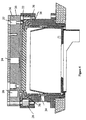
- the magnetron includes a body 20 in which is mounted a target 22 of material to be sputtered.
- a first array of magnets comprising a centrally mounted magnet 24 with a first polarity relative to the target and a series of magnets 26 to the rear of the target with a reverse polarity to the centre magnet relative to the target.
- a second array of magnets 28 to the side and around the periphery of the target 22 which are arranged with the same polarity relative to the target as the series of magnets 26 of the first array.
- the magnetic field 30 created by this arrangement is shown in broken lines and, as will be seen, the addition of the second array of magnets serves to "push" the effect of the magnet field towards the centre of the target material and thus a magnetic field effect as indicated by the line 32 is created in an area with a limit which is substantially parallel with the surface of the target.
- the effect of the second magnet array is to provide a magnetic field which is effective across substantially all of the target surface. This means that the material is sputtered from substantially all areas of the surface of the target to create a relatively even erosion pattern on the same and this is indicated in Figure 5 where it can be seen that the eroded target has a significantly more even erosion pattern than the erosion pattern on the target of Figure 2 using the conventional magnetron.
- the rear of the target 22 is shown in plan in Figure 6 in schematic form and indicates the arrangement of the first magnet array including magnet 24 and series of magnets 26 to the rear of the target and the second array of magnets 28 around the periphery of the target.
- the series of magnets 26 and second array of magnets need not be provided in an annular arrangement, which in this case is provided as the target is circular in shape, but may be provided in whatever spaced arrangement is required to suit the shape of the target used and the size of the same.
- the magnetron body 20 includes a target material 22.
- a first array of magnets is provided comprising a centre magnet 24 and a series of magnets 26 to the rear of the target and mounted in the body and a second array of magnets 28 is provided around the periphery of the target 22.
- a shield 34 which prevents the build up of contaminants in the area 36, a dual purpose buffer between the cathode potential, the target 22, and the earthed body 38 of the device is provided, which also serves as a retainer for the magnet array 28.
- the magnets of at least the second array of magnets are held in an insulating material and so in use they are provided with a floating potential or electrically grounded, with the target acting as the cathode of the magnetron during use.
- the provision of the magnets in this arrangement is convenient, and allows the magnetron to be operated without concern of the value of the magnets potential at that instant affecting the operation of the same.
- the shield 34 additionally prevents the oxidation and contamination of the area adjacent the periphery of the target material.
- the magnetron body 20 and the target insulator 36 are manufactured from an insulating material such as Delrin and, when clamped together, serve to insulate the live part of the magnetron which includes the target and the mounting plate therefor from the external surfaces of the magnetron thereby allowing handling of the magnetron by the operator even when live without the risk of electric shock.
- the connection 27 serves as a power connector to the magnetron target 22.
- the magnetron of this invention is particularly suited for use in apparatus for the sputter deposition of material onto substrates held in a chamber in which a vacuum is created.
- the apparatus of this sort comprises a chamber, a holder for a plurality of substrates movably mounted within the chamber, a means for creating a vacuum in the chamber, and at least one of the magnetrons according to the present invention with first and second arrays of magnets and a target of material arranged to be sputter deposited onto the substrates by operation of the magnetron.
- the apparatus includes two of said magnetrons, each provided with a target of a material to be sputter deposited onto the substrates, which are typically opthalmic lenses, to form a multilayered coating thereon.
Description
Claims (9)
- A magnetron including a body (20) with a target (22) formed of a material to be sputtered therefrom, first and second magnet arrays provided for creating a magnetic field (30) when activated, across a surface of the target material and a power supply for the activation of the magnetron, said first array of magnets being positioned at the rear of the target of material and comprising at least one centre magnet (24) with a first polarity in relation to the target and a series of magnets (26) arranged around the centre magnet with a polarity which is the reverse to that of the centre magnet, and the second array of magnets (28) having a polarity in relation to the target matching that of the series of magnets (26) of the first array, and characterised in that said second array of magnets is provided at the periphery of the target, spaced around the same and located in a side wall of the body (20) of the magnetron to lie at least partially to the front of the plane in which the target lies, with the axes of the said magnets (28) of the second array arranged to be substantially parallel to the target surface.
- A magnetron according to claim 1 characterised in that the spacing of the magnets (28) of the second array is determined by the strength of the magnets provided and the shape and surface area of the target.
- A magnetron according to claim 1 characterised in that the second magnet array (28) is fixed in relation to the target (22) and the first and second magnet arrays create a substantially uniform magnetic field which extends substantially across the surface of the target (22).
- A magnetron according to claim 1 characterised in that the magnets of the first and/or second arrays are mounted in insulating material.
- A magnetron according to claim 1 characterised in that the magnets, in use, are grounded or provided with a floating potential in relation to the target.
- A magnetron according to claim 5 characterised in that the magnets are enclosed by a shield (34) which is grounded thereby grounding the magnets during use.
- A magnetron according to claim 1 characterised in that the magnetron body in which the magnets, and to which the target material, are mounted, is formed of an insulating material to ensure that the body is not live during operation of the magnetron.
- A magnetron according to claim 7 characterised in that the target material is mounted between two parts of the body (20, 36), both of which are insulated and to which a power connection (27) is provided such that no live parts of the body are exposed.
- A magnetron according to claim 1 characterised in that the body of the magnetron includes an earthed shield (34) which is mounted to the front of the target material (22) to prevent build up of sputtered material around the periphery of the target.
Applications Claiming Priority (3)
| Application Number | Priority Date | Filing Date | Title |
|---|---|---|---|
| GB9606920 | 1996-04-02 | ||
| GBGB9606920.8A GB9606920D0 (en) | 1996-04-02 | 1996-04-02 | Magnet array for magnetrons |
| PCT/GB1997/000918 WO1997037371A1 (en) | 1996-04-02 | 1997-04-02 | Magnet array for magnetrons |
Publications (2)
| Publication Number | Publication Date |
|---|---|
| EP0892984A1 EP0892984A1 (en) | 1999-01-27 |
| EP0892984B1 true EP0892984B1 (en) | 2002-09-04 |
Family
ID=10791463
Family Applications (1)
| Application Number | Title | Priority Date | Filing Date |
|---|---|---|---|
| EP97915568A Expired - Lifetime EP0892984B1 (en) | 1996-04-02 | 1997-04-02 | Magnet array for magnetrons |
Country Status (6)
| Country | Link |
|---|---|
| US (1) | US6159351A (en) |
| EP (1) | EP0892984B1 (en) |
| AU (1) | AU2299897A (en) |
| DE (1) | DE69715180T2 (en) |
| GB (1) | GB9606920D0 (en) |
| WO (1) | WO1997037371A1 (en) |
Cited By (1)
| Publication number | Priority date | Publication date | Assignee | Title |
|---|---|---|---|---|
| US10014163B2 (en) | 2011-06-07 | 2018-07-03 | Vision Ease, Lp | Application of coating materials |
Families Citing this family (13)
| Publication number | Priority date | Publication date | Assignee | Title |
|---|---|---|---|---|
| US6579421B1 (en) | 1999-01-07 | 2003-06-17 | Applied Materials, Inc. | Transverse magnetic field for ionized sputter deposition |
| US6610184B2 (en) | 2001-11-14 | 2003-08-26 | Applied Materials, Inc. | Magnet array in conjunction with rotating magnetron for plasma sputtering |
| US8696875B2 (en) * | 1999-10-08 | 2014-04-15 | Applied Materials, Inc. | Self-ionized and inductively-coupled plasma for sputtering and resputtering |
| US10047430B2 (en) | 1999-10-08 | 2018-08-14 | Applied Materials, Inc. | Self-ionized and inductively-coupled plasma for sputtering and resputtering |
| JP4371569B2 (en) * | 2000-12-25 | 2009-11-25 | 信越化学工業株式会社 | Magnetron sputtering apparatus and photomask blank manufacturing method using the same |
| US7041201B2 (en) * | 2001-11-14 | 2006-05-09 | Applied Materials, Inc. | Sidewall magnet improving uniformity of inductively coupled plasma and shields used therewith |
| US6623610B1 (en) * | 2002-03-02 | 2003-09-23 | Shinzo Onishi | Magnetron sputtering target for magnetic materials |
| US20040055883A1 (en) * | 2002-03-02 | 2004-03-25 | Shinzo Onishi | Magnetron sputtering target for non-magnetic materials |
| US7504006B2 (en) * | 2002-08-01 | 2009-03-17 | Applied Materials, Inc. | Self-ionized and capacitively-coupled plasma for sputtering and resputtering |
| US20070007130A1 (en) * | 2005-07-11 | 2007-01-11 | Heraeus, Inc. | Enhanced magnetron sputtering target |
| WO2008090982A1 (en) * | 2007-01-26 | 2008-07-31 | Osaka Vacuum, Ltd. | Sputter method and sputter device |
| US20100018857A1 (en) * | 2008-07-23 | 2010-01-28 | Seagate Technology Llc | Sputter cathode apparatus allowing thick magnetic targets |
| US20130146451A1 (en) * | 2011-12-07 | 2013-06-13 | Intermolecular, Inc. | Magnetic Confinement and Directionally Driven Ionized Sputtered Films For Combinatorial Processing |
Family Cites Families (13)
| Publication number | Priority date | Publication date | Assignee | Title |
|---|---|---|---|---|
| US4060470A (en) * | 1974-12-06 | 1977-11-29 | Clarke Peter J | Sputtering apparatus and method |
| GB2096177B (en) * | 1981-04-07 | 1985-07-17 | Fournier Paul R | Improved integrated sputtering apparatus and method |
| US4407708A (en) * | 1981-08-06 | 1983-10-04 | Eaton Corporation | Method for operating a magnetron sputtering apparatus |
| JPS5976875A (en) * | 1982-10-22 | 1984-05-02 | Hitachi Ltd | Magnetron type sputtering device |
| JPS59173265A (en) * | 1983-03-22 | 1984-10-01 | Fujitsu Ltd | Sputtering device |
| JPS62218562A (en) * | 1986-03-19 | 1987-09-25 | Fujitsu Ltd | Sputtering device |
| EP0295649B1 (en) * | 1987-06-16 | 1994-12-14 | Hitachi, Ltd. | Magnetron sputter apparatus and method for forming films by using the same apparatus |
| DE3844064A1 (en) * | 1988-12-28 | 1990-07-05 | Leybold Ag | MAGNETRON PRINCIPLE CATALOG SPRAYING DEVICE WITH A HOLLOW CATODE AND A CYLINDRICAL TARGET |
| US5171415A (en) * | 1990-12-21 | 1992-12-15 | Novellus Systems, Inc. | Cooling method and apparatus for magnetron sputtering |
| TW271490B (en) * | 1993-05-05 | 1996-03-01 | Varian Associates | |
| DE4329155A1 (en) * | 1993-08-30 | 1995-03-02 | Bloesch W Ag | Magnetic field cathode |
| JP2627861B2 (en) * | 1993-10-22 | 1997-07-09 | アネルバ株式会社 | Method and apparatus for forming Ti-TiN laminated film |
| US5795451A (en) * | 1997-06-12 | 1998-08-18 | Read-Rite Corporation | Sputtering apparatus with a rotating magnet array |
-
1996
- 1996-04-02 GB GBGB9606920.8A patent/GB9606920D0/en active Pending
-
1997
- 1997-04-02 US US09/155,636 patent/US6159351A/en not_active Expired - Lifetime
- 1997-04-02 WO PCT/GB1997/000918 patent/WO1997037371A1/en active IP Right Grant
- 1997-04-02 EP EP97915568A patent/EP0892984B1/en not_active Expired - Lifetime
- 1997-04-02 DE DE69715180T patent/DE69715180T2/en not_active Expired - Lifetime
- 1997-04-02 AU AU22998/97A patent/AU2299897A/en not_active Abandoned
Cited By (1)
| Publication number | Priority date | Publication date | Assignee | Title |
|---|---|---|---|---|
| US10014163B2 (en) | 2011-06-07 | 2018-07-03 | Vision Ease, Lp | Application of coating materials |
Also Published As
| Publication number | Publication date |
|---|---|
| US6159351A (en) | 2000-12-12 |
| DE69715180D1 (en) | 2002-10-10 |
| GB9606920D0 (en) | 1996-06-05 |
| AU2299897A (en) | 1997-10-22 |
| EP0892984A1 (en) | 1999-01-27 |
| DE69715180T2 (en) | 2003-05-15 |
| WO1997037371A1 (en) | 1997-10-09 |
Similar Documents
| Publication | Publication Date | Title |
|---|---|---|
| EP0892984B1 (en) | Magnet array for magnetrons | |
| US6197165B1 (en) | Method and apparatus for ionized physical vapor deposition | |
| US5800688A (en) | Apparatus for ionized sputtering | |
| US5130005A (en) | Magnetron sputter coating method and apparatus with rotating magnet cathode | |
| US20060032741A1 (en) | Sputtering cathode adapter assembly and method | |
| US5409590A (en) | Target cooling and support for magnetron sputter coating apparatus | |
| KR100532805B1 (en) | Apparatus and method for depositing a film on a substrate | |
| WO2006038407A2 (en) | Vacuum film forming apparatus | |
| JP4306958B2 (en) | Vacuum sputtering equipment | |
| KR20010043955A (en) | Contoured sputtering target | |
| EP0737999B1 (en) | A magnetron sputtering system | |
| KR20130035256A (en) | Sputter deposition device | |
| KR20010041917A (en) | Sputtering apparatus with a coil having overlapping ends | |
| KR19980070371A (en) | Back-sputtering shield | |
| US6475353B1 (en) | Apparatus and method for sputter depositing dielectric films on a substrate | |
| WO1997035044A1 (en) | Method and apparatus for rf diode sputtering | |
| EP0544831A1 (en) | Method of improving ion flux distribution uniformity on a substrate. | |
| EP0555339B1 (en) | Magnetron sputter coating method and apparatus with rotating magnet cathode | |
| JP2794936B2 (en) | Plasma processing equipment | |
| JP3808148B2 (en) | Composite sputtering cathode and sputtering apparatus using the cathode | |
| JP2002043094A (en) | Plasma treatment apparatus and cleaning method of the same | |
| TW400538B (en) | Method and apparatus for selectively attracting or repelling ionized materials from a target surface in physical vapor deposition | |
| JPH0681146A (en) | Magnetron sputtering device | |
| JPS63282259A (en) | Sputtering device | |
| US20090145747A1 (en) | Method and installation for the vacuum colouring of a metal strip by means of magnetron sputtering |
Legal Events
| Date | Code | Title | Description |
|---|---|---|---|
| PUAI | Public reference made under article 153(3) epc to a published international application that has entered the european phase |
Free format text: ORIGINAL CODE: 0009012 |
|
| 17P | Request for examination filed |
Effective date: 19980921 |
|
| AK | Designated contracting states |
Kind code of ref document: A1 Designated state(s): CH DE FR GB IT LI |
|
| 17Q | First examination report despatched |
Effective date: 19990303 |
|
| GRAG | Despatch of communication of intention to grant |
Free format text: ORIGINAL CODE: EPIDOS AGRA |
|
| GRAG | Despatch of communication of intention to grant |
Free format text: ORIGINAL CODE: EPIDOS AGRA |
|
| GRAH | Despatch of communication of intention to grant a patent |
Free format text: ORIGINAL CODE: EPIDOS IGRA |
|
| GRAH | Despatch of communication of intention to grant a patent |
Free format text: ORIGINAL CODE: EPIDOS IGRA |
|
| GRAA | (expected) grant |
Free format text: ORIGINAL CODE: 0009210 |
|
| AK | Designated contracting states |
Kind code of ref document: B1 Designated state(s): CH DE FR GB IT LI |
|
| REG | Reference to a national code |
Ref country code: GB Ref legal event code: FG4D |
|
| REG | Reference to a national code |
Ref country code: CH Ref legal event code: EP |
|
| REF | Corresponds to: |
Ref document number: 69715180 Country of ref document: DE Date of ref document: 20021010 |
|
| ET | Fr: translation filed | ||
| REG | Reference to a national code |
Ref country code: CH Ref legal event code: NV Representative=s name: ABREMA AGENCE BREVETS ET MARQUES GANGUILLET & HUMP |
|
| PLBE | No opposition filed within time limit |
Free format text: ORIGINAL CODE: 0009261 |
|
| STAA | Information on the status of an ep patent application or granted ep patent |
Free format text: STATUS: NO OPPOSITION FILED WITHIN TIME LIMIT |
|
| 26N | No opposition filed |
Effective date: 20030605 |
|
| REG | Reference to a national code |
Ref country code: GB Ref legal event code: 732E |
|
| REG | Reference to a national code |
Ref country code: CH Ref legal event code: PUE Owner name: EDWARDS HIGH VACUUM INTERNATIONAL LIMITED Free format text: APPLIED VISION LIMITED#10 THE COURTYARD, WHITWICK BUSINESS PARK, STENSON ROAD#WHITWICK, LEICESTERSHIRE LE67 4JP (GB) -TRANSFER TO- EDWARDS HIGH VACUUM INTERNATIONAL LIMITED#CHERTSEY ROAD WINDLESHAM#SURREY GU20 6HJ (GB) |
|
| REG | Reference to a national code |
Ref country code: FR Ref legal event code: TP |
|
| PGFP | Annual fee paid to national office [announced via postgrant information from national office to epo] |
Ref country code: CH Payment date: 20080430 Year of fee payment: 12 |
|
| REG | Reference to a national code |
Ref country code: CH Ref legal event code: PL |
|
| PG25 | Lapsed in a contracting state [announced via postgrant information from national office to epo] |
Ref country code: LI Free format text: LAPSE BECAUSE OF NON-PAYMENT OF DUE FEES Effective date: 20090430 Ref country code: CH Free format text: LAPSE BECAUSE OF NON-PAYMENT OF DUE FEES Effective date: 20090430 |
|
| PGFP | Annual fee paid to national office [announced via postgrant information from national office to epo] |
Ref country code: FR Payment date: 20120227 Year of fee payment: 16 |
|
| PGFP | Annual fee paid to national office [announced via postgrant information from national office to epo] |
Ref country code: IT Payment date: 20120229 Year of fee payment: 16 |
|
| PGFP | Annual fee paid to national office [announced via postgrant information from national office to epo] |
Ref country code: DE Payment date: 20120216 Year of fee payment: 16 |
|
| REG | Reference to a national code |
Ref country code: GB Ref legal event code: 732E Free format text: REGISTERED BETWEEN 20130822 AND 20130828 |
|
| PG25 | Lapsed in a contracting state [announced via postgrant information from national office to epo] |
Ref country code: DE Free format text: LAPSE BECAUSE OF NON-PAYMENT OF DUE FEES Effective date: 20131101 |
|
| REG | Reference to a national code |
Ref country code: FR Ref legal event code: ST Effective date: 20131231 |
|
| REG | Reference to a national code |
Ref country code: DE Ref legal event code: R119 Ref document number: 69715180 Country of ref document: DE Effective date: 20131101 |
|
| PG25 | Lapsed in a contracting state [announced via postgrant information from national office to epo] |
Ref country code: IT Free format text: LAPSE BECAUSE OF NON-PAYMENT OF DUE FEES Effective date: 20130402 Ref country code: FR Free format text: LAPSE BECAUSE OF NON-PAYMENT OF DUE FEES Effective date: 20130430 |
|
| PGFP | Annual fee paid to national office [announced via postgrant information from national office to epo] |
Ref country code: GB Payment date: 20150217 Year of fee payment: 19 |
|
| GBPC | Gb: european patent ceased through non-payment of renewal fee |
Effective date: 20160402 |
|
| PG25 | Lapsed in a contracting state [announced via postgrant information from national office to epo] |
Ref country code: GB Free format text: LAPSE BECAUSE OF NON-PAYMENT OF DUE FEES Effective date: 20160402 |