EP0892347B1 - Paralleles Dateiensystem und Verfahren zur unabhängigen Datenaufzeichnung - Google Patents
Paralleles Dateiensystem und Verfahren zur unabhängigen Datenaufzeichnung Download PDFInfo
- Publication number
- EP0892347B1 EP0892347B1 EP98304753A EP98304753A EP0892347B1 EP 0892347 B1 EP0892347 B1 EP 0892347B1 EP 98304753 A EP98304753 A EP 98304753A EP 98304753 A EP98304753 A EP 98304753A EP 0892347 B1 EP0892347 B1 EP 0892347B1
- Authority
- EP
- European Patent Office
- Prior art keywords
- file
- node
- disk
- file system
- token
- Prior art date
- Legal status (The legal status is an assumption and is not a legal conclusion. Google has not performed a legal analysis and makes no representation as to the accuracy of the status listed.)
- Expired - Lifetime
Links
Images
Classifications
-
- G—PHYSICS
- G06—COMPUTING; CALCULATING OR COUNTING
- G06F—ELECTRIC DIGITAL DATA PROCESSING
- G06F9/00—Arrangements for program control, e.g. control units
- G06F9/06—Arrangements for program control, e.g. control units using stored programs, i.e. using an internal store of processing equipment to receive or retain programs
- G06F9/46—Multiprogramming arrangements
- G06F9/52—Program synchronisation; Mutual exclusion, e.g. by means of semaphores
-
- G—PHYSICS
- G06—COMPUTING; CALCULATING OR COUNTING
- G06F—ELECTRIC DIGITAL DATA PROCESSING
- G06F16/00—Information retrieval; Database structures therefor; File system structures therefor
- G06F16/10—File systems; File servers
- G06F16/18—File system types
- G06F16/1858—Parallel file systems, i.e. file systems supporting multiple processors
Definitions
- This invention is related to computers and computer systems, and in particular to a file system running on multiple computers each having their own instance of an operating system and being coupled for data sharing with network attached shared disks, a shared disk file system.
- Shared File System (See U. S. Patent 5,043,876 ) is a term applied to IBM's S/390 systems which operate under IBM's VM for sharing data among virtual machines.
- Shared file systems also have been known as data sharing vehicles, such as IBM's IMS and GRS, where developed for a single-system environment, and under MVS GRS was used in a cluster of systems sharing disk storage, and GRS in such a system could allocate small lock files on shared disk in order to serialize access to data sets.
- MVS must serialize access to the table of contents on disks or to the catalog, so whatever RESERVES operations are needed for the operating system to perform. This causes a good deal of system overhead.
- IBM's DB2 has been adapted for data sharing in a Multiple Virtual Storage (MVS) / Enterprise Systems Architectures (ESA) environment by using IBM's coupling facility to create multisystem data sharing which requires a System/390 Parallel Sysplex environment because the coupling facility is needed to deliver highly efficient and scalable data sharing functions where the coupling facility manages connections between processors with a message path mechanism as outlined in U. S. Patent 5,463,736 , essentially becoming the super-single server for the shared data.
- MVS Multiple Virtual Storage
- ESA Enterprise Systems Architectures
- VSD Virtual Shared Disk
- VSD software allows multiple nodes, running independent images of the operating system, to access a disk device physically attached only to one of the nodes as if the disk device were attached to all nodes, which IBM has implemented for the AIX operating system with a transparent switchover to a secondary server node when the primary server node for a set of virtual shared disks fail.
- the existence of the single server is both a bottleneck and a potential failure point, even though there have been substantial advances made with such single server systems, like IBM's VideoCharger, as illustrated by U. S. Patent 5,454,108 's lock manager, U. S. Patent 5,490,270 and 5,566,297 's cluster arrangement.
- a preferred embodiment of the present invention provides a shared disk file system where a file system instance on each machine has identical access to all of the disks coupled to and forming a part in the file system. This can occur using a gateway processor, a switched network, a high speed intranet coupling as would support TCP/IP, a non-uniform memory access bus couplings or other similar connections.
- the shared disk file system supports disk read and write calls with associated management calls.
- the operating instance is a commonly available or standard and does not need to be changed to use our shared disk file system. We have provided new services needed to make our shared disk file system operate in a useful fashion.
- Our shared file system operates as a parallel file system in a shared disk environment.
- Speed in our scalable parallel file system has been improved by improving cache performance and space utilization.
- extended file attributes support access control lists, known as ACL's in the Unix world, which are for the first time operable in a parallel file system which is scalable in a shared disk environment.
- the directory service claims provide efficient insertion and deletion of files into data structures without major disruption to the data structures. This is critical in parallel systems where exclusive control must be obtained of regions to be modified.
- Our allocation map development provides the ability to allocate storage from the same pool of disks in parallel while maintaining full consistency of the metadata. This is important because each of the computers with access to the file system will wish to create additional data without regard to what is going on in the other computers.
- Our prefetch algorithms calculate the available I/O bandwidth and the application needs for data to determine the amount of data to prefetch. This is important in parallel systems where the demand for I/O can exceed the available bandwidth.
- Our cache performance developments balance pools of multiple accesses and while not related to parallel processing, it is a general file system improvement.
- the use of file attributes as a supporting mechanism is also applicable to non-parallel file systems; but within our overall parallel file system mechanisms it is very important because it allows an effective implementation of Access Control Lists in a parallel file system.
- Allowing parallel update on the same file or directory in a shared disk environment is provided.
- a metadata node for managing file metadata for parallel read and write actions.
- tokens are used for metadata node selection and identification, and we have enhanced token modes for controlling file size, as well as smart caching of byte range tokens using file access patterns and a byte range lock algorithm using a byte range token interface.
- file size is a type of metadata which changes frequently in a parallel update situation.
- Our parallel shared disk file system enables assignment of control of certain resources temporarily to a specific computer for modification. While this is the case, structures on the disk that are visible to other computers may be in a inconsistent state and must be corrected in the case of a failure.
- a method for extending standard logging and lock recovery to allow this recovery to occur while other computers continue to access most of the data on the file system we have also provided for the handling of the failure of the metadata node. This development involves correction of metadata which was under modification and a new computer becoming the metadata node for that file, as described below.
- Quota concept is well known by that name. It is a generic concept able to be used to manage the initial extent of a space, and this concept is used with other operating systems, such as those of S/390 systems. Generically, when we consider quotas, they need to be managed aggressively, so that locks are not constantly required to allocate new blocks on behalf of a user. We have provided recoverable local shares for Quota Management, as described below.
- quota is a limit on the amount of disk that can be used by a user or group of users
- a quota manager which accesses the single quota file
- Our development provides for immediate recovery in many situations where sufficient quota exists at the time of the failure.
- running a utility like the UNIX standard utility called "quotacheck" is required to complete the recovery.
- quotacheck a technique for running a quotacheck utility at the same time as applications using quatas with minimal interference.
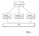
- Figure 1 illustrates a shared file disk system in accordance with our invention which includes a token manager for nodes of the computer system.
- FIGURE 1 An example of our preferred embodiment of our shared disk file system implementation of several relevant components is illustrated by FIGURE 1.
- Our system as illustrated in Figure 1, includes a token manager 11 which provides locking facilities for the computers which are considered nodes 1, 2, and 3 participating in the management of a file system. (N.B. For our token manager, we had to modify the lock manager of U.S. Patent 5,454,108 .)
- Our file system code manages reads and writes requested by applications. This management uses the application requests and the commonly managed metadata to create and access data within the file system. This function is the bulk of the processing and is identical on all computers. With proper tokens, this processing directly accesses the disk through the disk read, write and control functions.
- the shared disk implementation shown in FIGURE 1 and described in general above provides several major advantages over previous parallel and cluster file systems. It provides the shortest available path for moving the data from the disk to/from the using application. There is no file system server in the path for either data or metadata. Any available path can be used avoiding a server as a bottleneck or as a single point of failure. Since the required central functions in the lock manager have no attachment to a specific computer, they can be migrated from computer to computer to satisfy performance and availability needs.
- extendible hashing can use sparse files without storing an explicit hash table.
- directories in a Unix standard compliant file system, even though it is not so restricted.
- our preferred embodiment may be implemented with a Unix operating system environment, and that environment should be understood as a background, even though we contemplate other operating systems which use the same functions. Indeed, today, the base system can function with many operating system layers above the one actually employed in driving the machine which we call a computer.
- Both database systems as well as general purpose file systems allow storing and retrieving data by specifying a "key" that identifies a data record or a file.
- the file name serves as the key for accessing the data stored in the file; the structure that stores a set of file names and associated file access information is commonly called a directory.
- an auxiliary data structure called an index is often used to speed up lookups. An index allows finding a record in a database table or a file name in a directory without scanning the whole database table or directory.
- indexing methods based on hash tables as well as balanced search trees, such as AVL trees and B-trees.
- AVL trees and B-trees To achieve good lookup performance, these methods require reorganizing at least part of the index after inserting or deleting some number of data records. For example, inserting a record in a B-tree may require splitting a B-tree node into two new nodes to make room for the new record. As a result, existing records may need to be moved to a different physical location.
- an index update such as a B-tree split
- a sequential scan may move existing entries to a different location within the directory, inserting or deleting directory entries during a sequential scan will have undesired effects on the result of the scan: if an existing entry is moved, the sequential scan could miss the entry or it could return the same entry twice.
- hashing is a technique for storing and looking up data records by key that works well if an approximate bound on the number of records is known in advance.
- Hashing works by dividing the available storage space into a fixed number of "hash buckets".
- a mapping known as a "hash function” is applied that maps the key value to a hash bucket number; the new record is stored in the hash bucket given by the hash value.
- To find a record by key its hash value is computed; the requested record can then be found by scanning only the records stored in the bucket given by the hash value.
- the number of key values to be stored will not be known in advance and may grow arbitrarily large. This presents problems for the standard hashing technique, which requires that the maximum number of hash buckets be known from the start.
- An advanced form of hashing algorithm known as "extendible hashing” solves this problem by using a variable number of bits from the value of the hash function.
- a hash bucket fills it is "split", i.e., a new hash bucket is added and some of the records are moved from the existing hash bucket into the new one. Which records are moved is determined by re-evaluating the hash function and using one more bit to determine the hash bucket number: records where the additional bit is zero stay in the existing bucket, those with a one value for the additional bit are moved to the new bucket.
- an index or directory starts out with a single hash bucket, bucket number zero. As long as they fit, all records go into the initial bucket regardless of hash value, i.e., zero bits of the hash function are used to determine the hash bucket number. When the initial bucket is full, it is split by adding a new hash bucket, bucket number one. Now one bit of the hash function is used to place records: those records with a zero in the least significant bit of the hash value stay in bucket zero, those records where the least significant bit is one are moved into hash bucket one. New records are added to bucket zero or one depending on the value of the least significant bit of the hash value.
- hash bucket one fills up again and needs to be split.
- the two last bits of the hash function are now used to determine where the records from bucket one will be placed.
- Those records with bit values 01 stay in hash bucket one, those with bit values 11 go into a new hash bucket with bucket number three (binary 11 decimal 3).
- the records in hash bucket zero are not affected by the split, i.e., records with the last two bits 00 or 10 remain in bucket zero until bucket zero fills and needs to be split as well. It is also possible that bucket one fills up and needs to be split again before bucket zero is ever split.
- the directory structure after several hash bucket splits can be represented by a binary tree ("hash tree") as shown in the example in Table 1.
- a record can be found by traversing the tree from the root to a leaf node (hash bucket) using the hash value bits to decide which branch to follow at each inner node. Depending on the distribution of hash values, one branch of the hash tree may be become longer than others.
- hash function i.e., a function that generates evenly distributed hash values, we expect all tree branches to have approximately the same depth.
- a sequential directory scan is accomplished by a depth-first tree traversal, which will visit the leaf nodes (hash buckets) in left-to-right order.
- a hash tree is represented as a sparse file on disk, and records are relocated when a hash bucket is split, and a sequential directory scan traverses the hash tree in such a way that all existing entries are returned exactly once.
- sparse files are used in implementing extendible hashing.
- data written to a regular file is stored in one or more disk blocks on disk.
- Unix and Unix-like file system interfaces allow writing new data past the current end of a file, by issuing *seek* calls between write calls. This allows creating files with gaps or "holes", i.e., areas within a file to which no data was ever written. Such files are referred to as "sparse files”.
- Read operations on sparse files return zeros where the read offset and length intersect a hole.
- File system implementations that support sparse files efficiently allocate disk storage only for the areas of a file to which data was written, but not for holes, or at least not for holes that are larger than the block size or the unit of disk allocation used by the file system.
- An index or directory based on extendible hashing is implemented using a sparse file in our preferred embodiment.
- Each hash bucket is stored in the file at an offset given as i*s, where i is the hash bucket number (starting with zero) and s is the hash bucket size (all hash buckets have the same size).
- the directory starts out as an empty file.
- bucket 1 is written increasing the file size from s to 2*s.
- the next hash bucket split will write hash bucket 2 or 3, depending on which of the first two buckets needs to be split next.
- hash bucket number 3 will be written, increasing the file size from 2*s to 4*s, leaving the file with a hole at offset 2*s, where hash bucket 2 would go.
- Table 2 shows how the hash tree in the example from Table 1 would be stored in a sparse file.
- a record with a given key could be found by traversing the hash tree top down starting at the root (bucket zero). However, since we expect all tree branches to have approximately the same depth, it is more efficient to traverse the tree bottom up. This is done as follows. Given the file size, we can compute the depth of the longest hash tree branch, because in a hash tree with maximum depth d all hash bucket numbers are d bits or less and at least one hash bucket must have a bucket number where the d'th bit is one. Therefore, the maximum depth d can be computed as the number of bits in the largest hash bucket number, which is given by f/s - 1, where f is the file size.
- the extendible hashing implementation described here works with any hash bucket size, it will be more efficient if the bucket size is the same as the file system block size, or a multiple of the block size. This is because an efficient implementation of sparse files does not require any disk I/O to read a hole if the hole is aligned on file system block boundaries. Hence all lookups require at most one disk I/O to read the actual hash bucket that would hold the record, if that hash bucket is not currently cached. Note that this assumes that the file metadata that contains the location of the file's disk blocks is cached.
- Each hash bucket contains a header with a "hash tree level" field. The value of this field indicates the level of the hash bucket within the hash tree, i.e., how far the bucket is removed from the root of the hash tree.
- the tree has only one bucket, bucket zero at hash tree level zero.
- bucket zero When bucket zero is split, its hash tree level changes from zero to one; the new bucket number one is a sibling of bucket zero after the split, i.e., it will have hash tree level one as well.
- Each time a hash bucket is split its level is increased by one and the new bucket that is added is assigned the same hash tree level as the one that was split.
- Another requirement of the sequential scan is that the offset of a record within a hash bucket remains stable once the record has been inserted. Therefore, when we insert or delete a record in a hash bucket, existing records are left at their original location, i.e., there is no free-space compaction. Furthermore, when a record is moved to a new hash bucket due to a split, we store the record in the new bucket at the same relative offset as in the original hash bucket. This, together with the hash tree levels, allows reconstructing the content of a hash bucket before it was split.
- a scan operation in order to support a sequential scan of all records in a directory or index a scan operation is provided that can be invoked repeatedly to return the contents of the hash tree, something we call a sequential directory scan. Each call returns one or more records plus a "cursor" value that must be passed to the next scan call in order to retrieve the next set of records.
- This directory scan works if no records are inserted or deleted while the scan is in progress and then consider how to handle hash tree changes due to inserts or deletes between calls to the scan routine.
- next hash bucket in the hash tree in a depth first tree traversal order.
- the next hash bucket after bucket bl is not a sibling, but shares a common ancestor with hash bucket bl at a depth of d-1 in the tree.
- the next leaf node in depth first tree traversal order is found by taking the d least significant bits of b, reversing those bits, adding one modulo 2 ⁇ d to the resulting value, and reversing the result again.
- a scan operation invoked with a cursor value (b,r) first checks whether there are any more records at an offset greater than or equal to r in hash bucket b. If so, the scan returns the next record after r and a new cursor value (b,r'), where r' is the next offset after the record that was returned.
- Hash tree changes due to inserts or deletes are handled in between calls to the scan routine. Since we do not move existing records within a block to insert a new record or to delete an old record, the sequential scan is not affected by inserts and deletes as long as they do not result in a hash bucket split or merge. Since existing records do not move in this case, the scan will find each record at most once, and is guaranteed to return all existing records, except for those that are deleted while the scan is in progress. A newly inserted or deleted record may or may not be found depending on the position of the record (hash bucket and offset) and the timing of the insert/delete relative to the hash tree traversal by the sequential scan. A hash bucket split or merge does not affect the sequential scan either, if the split/merge happens before the sequential scan reaches the hash buckets affected by the split/merge or if it happens after the scan has proceeded past the affected buckets.
- This invention solves these problems by detecting a split or merge of a hash bucket that would affect the sequential scan, and by reconstructing the state of the hash bucket before the split/merge when necessary in order to continue the scan without missing or duplicating records.
- the hash tree level h given by the cursor value is compared to the current hash tree level h' found in the header of the hash bucket. If h' > h, then hash bucket b must have been split between the two calls to the scan routine; if h' ⁇ h, or if hash bucket b no longer exists (the file now contains a hole at offset b*s), it must have been merged.
- Hash bucket splits (h' > h) are handled by reconstructing the hash bucket as it existed when the cursor was generated.
- a temporary buffer is used to hold the reconstructed hash bucket.
- Descendants of the original hash bucket are read one at a time, and any records that existed in the original hash bucket b are copied into the temporary buffer.
- the records to be copied are identified by examining the hash tree level stored together with each record as described in the previous section: all records with a hash tree level less than or equal to h already existed before hash bucket b was split and are therefore copied.
- the scan routine then continues processing using the reconstructed block in the temporary buffer. When it reaches the end of the temporary buffer, the scan routine computes the next hash bucket to visit using the bit-reverse/increment procedure described above with a value of d that is given by the hash tree level h from the scan cursor.
- hash bucket merges are handled during a sequential scan.
- the hash tree level and hash bucket number can be combined into a single value requiring only one more bit than the number of bits required to hold the largest permissible bucket number. This is possible because the bucket number must always be less then or equal to 2 ⁇ L, where L is the level.
- the encoding is below.
- One parameter used by this encoding is the maximum hash tree level. i.e., the maximum depth to which any branch of the tree can grow.
- Cursor encoding for hash tree level L and hash bucket number B :
- the system can implement locking and concurrency control to allow concurrent updates in different hash buckets and also implement overflow blocks. While we don't really need a temporary buffer to handle splits during a sequential scan, we could use the buffer provided by the caller. In particular, one could imagine applications using a sequential scan interface that returns only one record at a time (e.g., database?), where it doesn't make sense to reconstruct a whole bucket just to return a one record.
- Parallel allocation is a feature of our preferred embodiment. This means that we provide for encoding an allocation map (e.g. a bit map) that, in comparison to a conventionally encoded allocation map, reduces the interference among multiple nodes simultaneously allocating disk blocks on multiple disks comprising a shared-disk file structure. Our system also allows multiple nodes to simultaneously deallocate disk blocks with reduced interference.
- an allocation map e.g. a bit map
- a file system is a computer program that allows other application programs to store and retrieve data on media such as disk drives.
- media such as disk drives.
- a file is a named data object of arbitrary size.
- the file system allows application programs to create files and give them names, to store (or write) data into them, to read data from them, to delete them, and perform other operations on them.
- a file structure is the organization of data on the disk drives.
- the file structure contains metadata: a directory that maps file names to the corresponding files, file metadata that contains information about the file, most importantly the location of the file data on disk (i.e. which disk blocks hold the file data), an allocation map that records which disk blocks are currently in use to store metadata and file data, and a superblock that contains overall information about the file structure (e.g. the locations of the directory, allocation map, and other metadata structures).
- a shared disk file system is one in which a file structure residing on one or more disks is accessed by multiple file systems running on separate computers.
- these computers or nodes have no shared memory (even though they could and in many likely implementations would have local memory and at least some shared memory as do many SMPs) and are connected to the disks on which the file structure resides by some means such as a bus or a switching network, either of which may be considered a communication network for these purposes.
- the nodes communicate with each other by some similar means.
- a shared disk file system allows a computation that uses the file structure to be broken up into multiple pieces that can be run in parallel on multiple nodes. This allows the processing power of these multiple nodes to be brought to bear against the computation.
- An allocation map is part of our file structure.
- a file structure stored on N disks, D0, D1,...,DN-1.
- Each disk block in the file structure is identified by a pair (i,j), e.g. (5,254) identifies the 254th block on disk D5.
- the allocation map is typically stored in an array A, where the value of element A (i,j) denotes the allocation state (allocated/free) of disk block (i,j).
- the allocation map is typically stored on disk as part of the file structure, residing in one or more disk blocks.
- the file system reads a block of A into a memory buffer and searches the buffer to find an element A(i,j) whose value indicates that the corresponding block (i,j) is free. Before using block (i,j), the file system updates the value of A(i,j) in the buffer to indicate that the state of block (i,j) is allocated, and writes the buffer back to disk. To free a block (i,j) that is no longer needed, the file system reads the block containing A(i,j) into a buffer, updates the value of A(i,j) to denote that block (i,j) is free, and writes the block from the buffer back to disk.
- the first node sets A(X) to allocated
- the second node sets A(Y) to allocated
- both simultaneously write their buffered copies of the map block to disk Depending on which write is done first, either block X or Y will appear free in the map on disk. If, for example, the second node's write is executed after the first's, block X will be free in the map on disk.
- the first node will proceed to use block X (e.g. to store a data block of a file), but at some later time another node could allocate block X for some other purpose, again with the result of violating the integrity of the file structure.
- a node To avoid corrupting the file structure, a node must obtain a token for each bit map block before reading it into memory, and if the node modifies the block (i.e. by allocating or freeing a block), it must write the block to disk before releasing the token. Tokens are normally obtained from and released to a "distributed token manager" such as the lock manager described in U.S. Patent 5,454,108 . The overhead of obtaining tokens from the token manager, and of writing map blocks back to disk before releasing a token held on the block, can substantially degrade the performance of a shared disk file system.
- Striping is a technique to store successive data blocks (e.g. of a file) on distinct disks.
- the advantages of striping include high performance and load balancing.
- the file system writes successive blocks of a file to distinct disks according to some cyclic permutation of the disk numbers 0,...,N-1.
- N map blocks or the entire allocation map, if it is smaller than N blocks. The overhead of doing this is much higher than allocating N blocks contiguously on a single disk.
- the node writing the file may incur significant delays waiting for other nodes to release locks on the required allocation map blocks.
- a disk allocator using a segmented allocation map providing for storing and managing an allocation map that supports striping files across multiple disks, while minimizing the locking, I/O, and search overhead associated with allocating blocks.
- our disk allocator greatly reduces the number of allocation map blocks accessed when allocating a striped file.
- it greatly reduces the lock contention and allocation map block reading and writing when multiple nodes simultaneously allocate striped files.
- the basic idea behind the disk allocator describe here is to subdivide the allocation map into a number of regions. It the map is divided into K regions, each region controls 1/K of the blocks on each of the N disks.
- the file system locks regions, rather than individual allocation map blocks, to synchronize access to the map. By using distinct regions, multiple nodes can simultaneously allocate striped files without interfering with each other.
- each region contains MN/K elements of the allocation map.
- these MN/K elements fit in a single allocation map block, but if the number of disks (or the size of each disk) is sufficiently large, or if the number of regions is sufficiently small, regions may be larger than allocation map blocks.
- regions are composed of one or more segments, where each segment is at most the size of an allocation block and controls allocation of blocks on a subset of the N disks. If regions are less than half the size of map blocks, multiple regions are packed into each map block.
- the parameters that determine the organization of the segmented allocation map are the number of regions, K, as well as the number of disks, N, and the disk capacity expressed as the number of blocks per disk, M.
- the number of regions should be chosen to be at least as large as the number of file system nodes, so that each node can allocate from a different region.
- K must be chosen to be at least M/B: otherwise, d will be zero, i.e., the allocation map elements that refer to the same disk will not fit within a single block.
- Segments are laid out in successive allocation map blocks in the following order: S(0,0), S(1,0), S(2,0), ...,S(K-1,0), S(0,1), S(1,1), S(2,1), ...,S(K-1,1), ... S(0,L-1), S(1,L-1), S(2,L-1), ..., S(K-1,L-1).
- the first segment of each region is stored at the beginning of the allocation map, followed by the second segment of each region, and so on.
- This layout makes it possible to extend the file system by adding more disks without requiring a complete reorganization of the allocation map: adding more disks to the file system requires storing more allocation map elements in each region, which may require adding one or more segment to each region. (How many segments will be required is determined by re-calculating L with a new value for N). The additional segments are simply appended to the end of the existing allocation map.
- a node To allocate successive blocks of a striped file, a node obtains a token for a region and allocates successive blocks according to the striping permutation using free blocks in the region (i.e. blocks whose allocation map elements indicate their state is free). Before releasing the token, the node writes the region back to disk. If, when trying to allocate a block on a particular disk, the region is found to contain no free block on that disk, the node switches regions: it writes the region back to disk and releases the token, then obtains a token for another region and attempts to allocate from it.
- the node If the node unsuccessfully tries all regions in an attempt to find a free block on a particular disk, it can then either (depending on the file system's striping policy) allocate a block on another disk or return an "out of space" condition to the application. In the former case, when all disks have been unsuccessfully tried, the file system returns "out of space”.
- the file system would typically allow other nodes to "steal" the token for its region between file block writes.
- the node In response to a token steal request, the node writes the region to disk and relinquishes the token.
- To deallocate a block the file system reads in the region containing the allocation map describing the block, updates its state to free, and writes the region back to disk before releasing the token.
- an allocation manager which is a program that keeps track of which node (if any) is using each allocation region, and of approximately how much free space remains in each region.
- the allocation manager examines each region to count the number of free blocks in each, and keeps this information in a table.
- a file system node sends a message to the allocation manager to notify it of the region it is switching from (including the present amount of free space in the region), and to obtain a suggested region to switch to.
- the allocation manager updates its table to indicate the free space in the region being switched from and to show it as no longer in use.
- the allocation manager and file system provide means to direct block deallocation to the node (if any) that is currently using the region controlling the block being deallocated. This is implemented as follows: to delete a block, the file system first sends a message to the allocation manager to obtain the identity of the node presently using the region. The allocation manager responds with the node's identity, or an indication that the region is not in use. In the latter case, the node deallocates the block. In the former case, the node sends a message to the node indicated by the allocation manager, telling it to deallocate the block. If the second node indeed is using the region, it deallocates the block and responds to the first node to indicate that it has done so. If the second node is not using the region, it responds to the first node to inform it of this, whereupon the first node deallocates the block.
- deallocation messages can be batched. For example, when deleting a file the blocks that belong to the file can be sorted by allocation region, and a single deallocation message containing blocks that belong to the same region can then be sent to the node that is presently using that region.
- Prefetching is a technique used in file systems to reduce I/O latency by reading blocks of sequentially accessed files in advance of when the data is requested by application programs.
- Our system handles the problem of dynamically scheduling and adjusting file system resources devoted to prefetching, so as to maximize throughput and minimize I/O latency in a parallel file system, i.e., a file system in which data for the same file is distributed across multiple disk devices.
- buffer manager which arbitrates use of memory resources among different system components competing for memory.
- Each component must provide the buffer manager with information that the buffer manager needs in order to decide how much memory to allocate to each component. This information consists of the following two numbers:
- the buffer manager informs each component how much memory it has assigned for use by that component.
- file system buffer pool which is used to cache recently accessed file data and data that was prefetched for sequential readers.
- buffer manager with appropriate information to take into account resources required for prefetching, and schedule the resources assigned by the buffer manager so as to maximize file system throughput and minimize I/O latency.
- double buffering is sufficient to provide optimal throughput and performance.
- the file system reads the first block of the file into one of the prefetch buffers. As soon as the first I/O finishes, the file system reads the second block of the file into the other prefetch buffer. While the second I/O is in progress, read requests from the application are satisfied by retrieving file data from the first buffer. If the end of the first buffer is reached, subsequent read requests can be satisfied from the second buffer as soon as the second I/O finishes. Once the second I/O has completed, and the application has read the last byte from the first block, the first prefetch buffer is re-used to prefetch the third block of the file, and so on.
- prefetch I/Os will complete before the application has finished reading data in the previous block.
- the next prefetch I/O will be started as soon as the application has read the last byte of the previous buffer.
- data will be supplied as fast as the application reads it, and the application will never have to wait for disk I/O. This is optimal.
- the application reads the data faster than it can be retrieved from disk, it will need to wait for the currently active I/O to finish each time it reaches the end of one block, and a new prefetch I/O will be started as soon as the previous one finishes. In this case, data will be read as fast as it can be retrieved from disk, which is again optimal.
- the algorithm shown in Table 3 generalizes this behaviour to multiple application programs and multiple disks per file system; it computes a number of prefetch buffers required so that: (1) If the combined data rate at which all the application programs attempt to read data is less than the total available disk bandwidth, then data will be supplied to each application as fast as it reads the data, with no I/O waits. (2) If the combined data rate of the application programs is greater than the total available disk bandwidth, then data will be read as fast as it can be retrieved from disk.
- Both cases require determining the rate at which each application program attempts to read data. This is done by measuring the application "think time”, i.e., the time the application spends processing the data supplied by the file system.
- the think time includes overhead in the read system call for accessing data in the file system buffer pool and for copying it into the application's buffer, but does not include time spend in the file system waiting for data to be read from disk.
- We define the application "data consumption rate" over some time interval to be the amount of data read by the application during the interval divided by the total think time in that interval.
- the number of prefetch buffers can be increased to take variations in consumption rates into account. This is done by not just measuring think time averages, but also the variance of the think time for each application. This is then used to compute a "variance adjusted consumption rate", i.e., a rate such that almost all read requests (e.g., 90% or 95% of all requests) arrive no earlier than the time predicted based on the variance adjusted consumption rate. This variance adjusted consumption rate is then used to compute the parallelism factor instead of the average consumption rate.
- the parallelism factor computed as described above will be a number that is larger than the number of disks available to the file system. Since it is not possible to start more concurrent I/Os than there are disks, there is no point in assigning more buffers for prefetch I/O as there are disks. Therefore, the desired number of prefetch buffers is calculated as the number of file instances open for sequential I/O plus the number of disks or the parallelism factor, which ever is smaller.
- this number of prefetch buffers will be sufficient to keep all disks busy, i.e., to start a new prefetch I/O as soon as the previous I/O on a disk has finished. Thus data will we supplied as fast as it can be retrieved from disk.
- the number of buffers devoted to prefetch I/O must be larger than the number of disks by a factor of (1+epsilon), where epsilon is given by the ratio of the average I/O request delay and the average disk I/O time.
- the second refinement in the buffer calculation takes into account limitations of I/O subsystem components such as disk controllers and I/O bus. If the number of file system disks is large, adding up disk bandwidth may yield a number that is larger than the total disk I/O throughput that the system can support. If this is the case, then the number of prefetch buffers devoted to prefetch I/O need not be as large as the number of disks. Instead, a number of buffers equal to the total I/O throughput divided by the bandwidth of a single disk will be enough to start as many disk I/Os in parallel as the system can effectively support.
- the total disk I/O throughput can be determined either from hardware specifications, by explicitly measuring troughput when the file system is installed, or by recording the maximum throughput ever observed while the file system is running.
- n_inst number of sequentially accessed open file instances
- n_para c_total/T_disk 3.
- Table 4 Scheduling prefetch I/O Input to this procedure is the actual number of prefetch buffers, n_bufs_assigned, that was assigned by the buffer manager based on the desired number of buffers, n_bufs_desired, computed as shown in Table 3.
- n_io_total is the number of prefetch I/O's currently in progress (or has been submitted to the device driver)
- n_prefetched is the number of buffers holding prefetched blocks that have not yet been read by the application for which the block was prefetched. The sum of these two numbers is the number of buffers currently in use for prefetching. Also, for each sequentially accessed open instance i, the algorithm keeps track of the predicted time at which the application will access the next block for which no prefetch I/O has been started yet. We denote this number by t_next[i]. 1. Initialize n_io_total and n_prefetched to zero.
- n_io[i] For each sequentially accessed open file instance i, initialize n_io[i] to zero, and Initialize t_next[i] to be the time at which the application will request the next data block, based on the adjusted consumption rate, c_i. Construct an ordered instance list by sorting all sequentially accessed open instances by t_next[i], smallest value first. 2. If n_io_total + n_prefetched is greater than or equal to n_bufs_assigned, goto step 4; otherwise, continue to the next step. 3. Submit the next prefetch I/O request for the first instance 1 in the ordered instance list (this will be the instance with smallest t_next[i] value).
- Update t_next[i] to be the predicted time at which the application will request the next data block after then one for which the prefetch I/O was just started. Re-order this instance in the ordered instance list of all instance according to'its new t_next[i] value Increment n_io_total. Go back to step 2. 4. Wait for one of the following events to occur: a) A prefetch I/O completes: Decrement n_io_total and increment n_prefetched Go back to the beginning of Step 4 (wait for the next event).
- Cur parallel file system is developed for use on IBM machines where performance is a crucial factor.
- One of the aspects that can affect performance is the file system's cache utilization.
- the problems is that requests for cache space of varying sizes are presented to the system in an unpredictable fashion.
- We have implemented a cache management scheme in which we identify the current usage pattern in the system and adjust the cache behaviour accordingly and thus improve on both performance and space utilization.
- the complete cache is split into different working units, each of which controls a portion of the complete cache space and is responsible for buffers of a different size.
- Each working unit is comprised of two sub-units that monitor the two kinds of workloads the system operates with.
- the amount of different working units and the buffer sizes that they are responsible for changes dynamically.
- the cache manager recognizes at each moment in time the buffer sizes for which, with a high probability, there will be a lot of demand, and sets up the working units accordingly.
- This aspect helps alleviate the problem of cache fragmentation by limiting the problem to one working unit and taking extra measures such as merging and re-mapping only there.
- Usage statistics are constantly updated for each sub-unit of every working unit.
- Each working unit has two kinds of space limits, namely, an internal and an external one.
- the internal space limit divides between the two sub-working units.
- the external space limit is further divided into two kinds of limits, namely the physical limit and the virtual limit.
- the physical limit represents the actual amount of space under control of the usage pattern scheme distribution that belongs to the individual working unit.
- the virtual limit is the one projected by the usage pattern analysis - prediction process as the physical limit this working unit should attempt to achieve.
- the virtual limit is used to deduce whether a specific working unit physical limit is allowed to grow or whether it is forced to give up a portion of the space under its control upon a request from a working unit that is allowed to grow, thus in essence it is allowed to shrink.
- the process of setting new virtual limits works as follows.
- the sub-working units' statistics are analyzed and used to deduce the usage pattern and activity level that determine the space optimally needed by it.
- Each sub-working unit attempts to obtain the amount of space it determined to be optimal for its needs, (its working set size).
- the relative activity level of the sub-working unit presents a cap on the optimally needed space.
- New space acquisition is governed by a scheme in which physical and virtual limits within each working unit interact as follows.
- the working unit which controls the size requested. If there is a free or a very easy and quick to obtain buffer in the working unit, it is used to satisfy the incoming request.
- the working unit then proceeds to compare its physical limit with its virtual limit. If the physical limit is not smaller than the virtual one, the working unit proceeds to find the easiest to obtain space already under its control. Otherwise the current working unit finds the working unit that is allowed to shrink the most and directs a space acquisition request to it.
- the receiving working unit finds the easiest to obtain space under its control, and gives up the control over it.
- the original working unit then proceeds to assume control over the new space and uses it to satisfy the incoming request.
- the frequency with which the usage pattern detection process is run might have a crucial impact on the effectiveness of the whole scheme. If the process is run too frequently it might react too harshly to very short activity peaks in a certain sub-working unit. On the other hand if this process is run at large intervals its effectiveness and accuracy is reduced as time passes. Thus each time the process runs, it determines when it should run next. That calculation is based on the expected time for all the working units to access all the space under their control. That period is subjected to pre-defined upper and lower bounds. This interval permits the usage pattern process to deduce the current workload distribution without being affected by a single straining event. The working set of random workload clients can be deduced as well as the space needed for read-ahead of sequential workload clients.
- This scheme encompasses added performance and usage of available cache space in a multi-purposed environment.
- each incoming request is directed towards the cache region which with a high probability will be used to satisfy it.
- the space amount that can be devoted for each workload in each working unit and thus can adjust other system actions accordingly, (e.g. prefetching rate).
- Extended attributes allow associating variable-length information with a file that can be accessed separately from the data stored in the file itself.
- extended attributes are for storing access control lists, "ACLs" for short, which are used to control what users or groups are permitted to access a file in what way (read, write, etc.).
- ACLs place demands on an extended attribute implementation that are unlike many other uses of extended attributes: Since all file system operations that check access permission need to access the file's ACL, quick and efficient access to the ACL data is critical to file system performance. On the other hand ACLs are typically short, do not change very frequently, and even if every file has an ACL, many of these ACLs will be the same, i.e. there are typically significantly fewer different ACL values than there are files.
- our extended attribute implementation in this invention employs the following components:
- attribute value sharing is provided as an extended attribute implementation. This allows sharing of physical attribute storage among all files that have attributes with identical values. This is accomplished by storing all attribute data in a common place, the place we would call the AttrFile.
- the AttrRef stored in the inode of a file "f" contains the location of the entry that holds the attribute data for "f" in the AttrFile, represented by the offset of the entry in the AttrFile.
- Files with identical attribute values will contain the same AttrRef values in their inode.
- ACLs do not commonly contain a long list of individual users, because such lists are difficult to manage. Rather, most systems allow defining user groups; a group can then be used in a ACL to refer to the users that belong to that group. Therefore, it is uncommon for ACLs to be very long, which means an ACL can usually be stored in a small amount of space. This fact, combined with ACL sharing, means that it will be possible to cache ACL data for a large number of files in memory. This makes it very efficient to retrieve the ACL for a file, because the ACL data is likely to be cached in memory, so that it can be accessed without additional disk I/O.
- ACLs for a large number of files are changed, it is likely that many of these ACLs will be changed to the same, new value. For example such a change would happen to grant a new user access to the files associated with a particular project.
- Due to ACL sharing only the first one of a set of related ACL change operations will require updating the AttrFile: subsequent ACL change operations using the same ACL value only require looking up the ACL value in the AttrIndex. This means that even under a workload with a large number of concurrent ACL updates, access to the AttrFile will be mostly read-only. Hence the fact that all attributes are stored in a common place will not cause a bottleneck problem. This is particularly important in a distributed environment where it is desirable to cache attribute data locally, which makes AttrFile updates much more expensive due to the need to invalidate attribute data cached on other nodes.
- Garbage collection is an ongoing need which needs to be provided. Attribute value sharing makes it somewhat more difficult to reclaim space in the AttrFile when an attribute entry is no longer needed.
- the problem is to detect when it is safe to delete the entry, i.e., when the last file that was referring to the entry is deleted or its attribute is changed.
- a common solution to this problem is to maintain a reference count for each entry; the reference count would be incremented when an AttrRet referring to the entry is stored in a file's inode and decremented when an AttrRef is deleted. The AttrFile entry could then be deleted when the reference count goes back to zero.
- this invention reclaims attribute space through garbage collection. Garbage collection finds and deletes unused attribute entries as follows. Part of each attribute entry is a reference flag, "RefFlag" for short, which is always set when a new entry is added to the AttrFile. Garbage collection proceeds in the following three phases:
- garbage collection needs to synchronize with the lookup operation that is a part of setting or changing a file attribute as described under "Attribute Value Lookup" in the section on "Attribute Value Sharing" above. Since garbage collection may take a relatively long timeespecially Phase 2 -- it is not desirable to simply disable all set/change-attribute operations while garbage collection is running. Instead, when a set/change-attribute operation finds and existing entry in the AttrFile with a value that matches the new value being set, it also checks whether the RefFlag in the entry is turned on before it stores the AttrRef in the file's inode. This way, explicit synchronization between garbage collection and attribute value lookup is necessary only during the last phase of garbage collection, and then only if the attribute value lookup finds an attribute entry with the RefFlag turned off.
- the process of starting the garbage collection process is important. Without garbage collection the AttrFile could keep growing without bounds even if the total amount of active attribute data (attribute values that are still referenced) does not.
- the rate at which the AttrFile would grow depends on the rate cf set/change-attribute operations. For attribute uses such as ACLs, the rate of such operations is essentially unpredictable. Therefore, a policy that starts garbage collection at fixed regular intervals (e.g., once a day) is not appropriate. Instead, we monitor the total size of attribute data, i.e., the size of the AttrFile minus the total free space in the AttrFile. Garbage collection is started every time the amount of attribute data has grown by a certain factor (e.g., 1.5 or 2) . This policy is effective in preventing the AttrFile from growing if the amount of active attribute data stays constant.
- a certain factor e.g. 1.5 or 2
- This section describes the operation of the metadata node which improves performance in those cases where multiple computers need to update or enlarge the same data object.
- a metadata node is used in our system for managing file metadata for parallel read and write in the shared-disk environment.
- the parallel file system makes it possible for any and all disks which make up the file system to independently be accessed by multiple processors. To exploit this capability, a file should be shared by multiple processors for both reading and writing.
- nodes may read and write to different areas of the file if they present an appropriate lock on the sections which they are reading or writing, they all need to access the same metadata.
- the metadata includes the file size, the file access and modification times, and the addresses of the file's data blocks. For example, all operations that read and write the file need to know if they exceed the file size, and update it if they extend the file. Such a single point of interest might present a serious bottle neck if true parallel write sharing to a file is needed.
- All the other nodes communicate with the metadata node in order to fetch or update metadata information. However, these nodes do not access the metadata information on the disk directly.
- the metadata node is elected to be the first node that accesses the file. Thus, if only one node needs to access the file, no extra overhead is incurred since the node can access the metadata directly. Additional nodes will access the metanode for metadata.
- the metanode keeps a cached copy of the metadata which reflects the metadata on disk.
- Other nodes also keep a cached copy of the metadata which they read in the past from the metanode, and which they augmented as needed (for example, changed the access time).
- Each metadata element (access time, modification time, file size, data block disk addresses) has its own pattern of usage and special characteristics. For example, our system does not require a very precise access time, but one which is correct within five minutes. Thus, updates to the metanode do not need to be frequent, and thus a considerable amount of communication is saved.
- the file size does not to be exact on all nodes, as long as the system behaves consistently.
- Using a sophisticated way to control the file size on all nodes allows a parallel write scheme where multiple nodes may extend the file concurrently.
- a sync daemon is a piece of software that runs as part of the operating system of each node. The sync daemon tries to flush dirty data and metadata to disk every N seconds. If M nodes write the file in parallel, this means M disk accesses every N seconds for the metadata only. With parallel write, all nodes send their updated metadata to the metanode, which flushes the file every N seconds when it gets a signal from the sync daemon.
- Every node would access the disk in order to read or write metadata.
- the second of the parallel write sections of this description relates to our use of lock modes for finding the metadata manager node. Tokens using lock modes of finding the metadata manager node are used for metadata node selection and identification in our parallel file system where all disks which make up the file system can independently be accessed by multiple processors. To exploit this capability, a file should be shared by multiple processors for both reading and writing.
- a node is appointed for each file which is responsible for accessing and updating the file's metadata.
- This metadata node (or metanode) shares this information with other nodes upon request.
- the metadata node keeps the information about the file's metadata and acts as a smart cache between the disk and all the nodes that access the file. There are situations when the metadata node (or metanode) ceases to serve this function. In order to enable smooth operation and recovery, these situations need to be handled. Nodes that used to access the metanode need to elect a new metanode in a straightforward way.
- metanode we elect metanode and make this information available to all nodes.
- the election process takes into account the access patterns of the file. There should be one, and only one, metanode per file. Also, the scheme should and does allow metanode takeover and recovery. In our system metanodes are selected and their information is known to other nodes.
- a token manager is a distributed subsystem which grants tokens to nodes. Every node can ask for a named token with a specific mode. The token manager grants the token to the node if the mode does not conflict with tokens with the same name which were granted to other nodes. For each token there is a list of the possible modes and a conflict table. If the requested token conflicts with a token which was granted to another node, a revoke is done and the conflicting node downgrades its token mode to a mode which does not conflict with the requested mode.
- the metadata node is elected to be the first node that accesses the file. Thus, if only one node needs to access the file, no messages are extra overhead is needed since the node can access the metadata directly. Additional nodes will access the metanode for metadata.
- a node opens a file for the first time, it tries to acquire the metanode token in mode "ww".
- the token manager TM grants the token in "ww” if it can, i.e., if no other node holds the token in "ww” or "xw”. If this happens, the node becomes the metanode manager. However, if another node holds the token in "ww”, then the TM grants the token in "ro". Then the node knows that another node is the metanode. It can query the TM to find out who the metanode for this file is.
- Read & write sharing of files involve accessing the file's size. Every read and write needs to check if the operation's offset is beyond the current file size, and return an EOF end-of-file) if it is. Every write needs to check if the operation's offset is beyond the current EOF, and if it is, it should extend it. When there are several readers and writers, all this has to be consistent. Thus, if one node writes at offset 1000, a read by any node at that location should not return an EOF.
- Some modes only allow reading the file size (rw rf). Some modes (wf, wa ) allow increasing the file size. One mode (xw) allows to decrease the file size.
- the true file size is the maximum of all the local copies of the file sizes that the nodes hold.
- Operations that read or write within the locally cached copy of the file size need an "rw” lock on the file size.
- Operations the read beyond the locally cached copy of the file size need to ensure that the file size did not increase since they last read the file size. Thus, they need to acquire an "rf” lock (which conflicts with modes that increase the file size).
- the only mode that allows decreasing the file size is "xw". This is an exclusive mode which will cause all other nodes to relinquish their locks and thus lose the locally cached file size. Thus, after the node that acquired the "xw" finishes its operation (for example, a file truncate), all the nodes will have to get the new file size from the metanode.
- the solution allows users on different nodes to extend the file and thus to achieve a very high degree of write sharing. Write operations do not need to be serialized even if the users extend the file size.
- Serializing accesses to different regions in a file to which processes on different nodes write in parallel is done by distributed byte range locks.
- the byte range token represents the node's access rights to a portion of a file.
- a node holds a byte range token for file X for range (100, 200) in read mode, it means that the node may safely read that portion of the file.
- the node must lock the token before the actual read, since if another node needs to write the same portion, it might steal the token. Locking the token prevents the steal. After the read has completed, the token is unlocked.
- tokens are a way of "caching" locks.
- a node needs to lock a portion of a file, it needs to lock the token. At first, it will acquire a token and lock it. Once the operation is finished and the token is unlocked, it is still resident at the node. Thus, subsequent operations on the same region would not need to access the token authority. Only when the token is stolen will a new request for the token be needed.
- a process may be of benefit to request a larger token than needed to be locked. For example, if a process reads a file sequentially, and it reads from range 1000 to 2000, then although the next lock will be of range 1000 to 2000, it can request a larger token, for example, from 1000 to 10000. However, this may create excessive token traffic on other nodes. If another node is in the process of writing from 5000 to 6000, the token acquisition may delay the operation.
- the idea is to give two ranges when acquiring a byte range token: a required range (which is the minimum range that is needed for the operation) and the desired range (which is the maximum range that is expected to be of any use).
- the token manager is guaranteed to grant a token that covers the required range but is not larger than the desired range.
- Two algorithms need to be specified: (1) how to compute the desired and required range for each operation; this is on the requesting side; (2) how to compute the granted range; this is on nodes which hold conflicting tokens.
- the main goal is to minimize token traffic.
- a token is requested.
- the required range is computed based on the offset and length of the file operation.
- the desired range is based of the access pattern of the file. If the file is accessed randomly, then the desired range will be equal to the required range, since there is probably no advantage in stealing tokens (that would probably not be needed) from other nodes. If, however, the file is accessed sequentially, the desired range starts from the required range's start, but ends at infinity (there's a special value to represent infinity. This is in attempt to minimize future token requests, since we can predict the future locks that will be needed.
- a node When a node holds a token that conflicts with a request for a token on another node, it gets a revoke request.
- the request contains the requesting node's required and desired ranges.
- the node has to make a decision what range it can relinquish. If the required range is equal to the desired range, the decision is easy, and the granted range is the required (and desired) range. However, if the desired range is different than the required range, that means that the requesting node is accessing the file sequentially, and it wishes to have a token that starts at the required range's start but ends at infinity.
- the node then makes a pass over all its active processes that access the file, and checks whether they access the file sequentially or randomly.
- the node grants the desired range. However, if one or more of the processes access the file sequentially, it would be a waste to relinquish the desired range, since with high probability we know what token will be requested soon. In this case, the file pointers (i.e., the anticipated location of the next operation) of all the sequential operations are examined, and the minimum offset is calculated. It is anticipated that these operations will not access file regions which are below this minimum, since they are sequential. Thus, the granted range is stretched to that calculated minimum, if it is higher than the required range.
- the solution allows caching of tokens with regard to the file access pattern. This saves acquisition of tokens which is a costly operation and thus improves the overall performance of the system.
- This parallel write improvement provides for the management of information describing tokens using a byte range lock algorithm with a byte range token interface.
- Our parallel file system where all disks that make up the file system can independently be accessed by multiple processors when exploited requires that a file should be shared by multiple processors for both reading and writing.
- a locking mechanism for regions in files is required.
- tokens are sometimes used. This token represents the access rights of a node to an object. However, a node might run several processes which try to access the same region of a file; thus, a local lock mechanism is needed on the tokens.
- TM Token Manager
- a node To get access to a region in a file, a node first has to get the appropriate token, then lock it, perform the operation, and unlock the token. There are several problems associated with locking the tokens; first, a token may already be cached in the node. In this case we do not need to acquire it again. Second, we must ensure that locks within the same node do not conflict; third, we must handle revoke requests from other nodes that need a token that conflicts with a token that we currently hold. Our locking algorithm presented here solves these problems efficiently.
- Our locking algorithm is presented as a set of APIs. Two APIs are used for locking and unlocking a byte range.
- a third API is a callback function called by the Token Manager. The Token Manager is assumed to provide three APIs as well.
- One API is needed to acquire a byte range token ("Acquire").
- a second API is needed to test whether a byte range token is already cached in the node ("Test”).
- a third API is needed when relinquishing a token as a response of a revoke (“Relinquish”).
- each token contains a range (start, end) of the region of the file which it can access.
- the algorithm that we implemented is also based on a fourth interface that has to be provided by the TM: Test(byte_range) which queries the TM for the existence of the token on the node.
- the algorithm is based on a lock table (Range lock table, or RLT), which holds all the existing locks.
- RLT ange lock table
- the table is protected by a mutex to enable atomic insertions and deletions of locks.
- Three main functions are exposed: LOCK, which locks a byte range; UNLOCK, which unlocks a previously locked range; and REVOKE, which handles a revoke request.
- One of the features of our invention is that we examine a token request for a specified byte range for comparing the request with the existing conflicting ranges in the entire multinode system and granting the largest possible byte range which does not require a toke revoke from another computer. This reduces the probability that the next operation on the requesting node would require another token request. Counters and non-blocking lock calls are used to acquire tokens while holding other locks. This technique allows more efficient serialization for multiple requests within a single node allowing the required multiple node serialization.
- the Acquire interface of the token manager takes as input a mode, as well as two ranges, a "required” range, and a “desired” range.
- the desired range must be a superset cf the required range.
- An application calling the Acquire interface is guaranteed that, at a minimum, it will be granted the required range.
- the token manager will determine if any conflicting ranges (ie, ranges that overlap the required range in a conflicting mode) have been granted to other nodes. If any conflicting ranges are found, then the token manager will request that each node that has a conflicting range downgrade the overlapping range to a non-conflicting mode.
- the Acquire interface will determine the largest, contiguous range which totally covers the required range, which is also a subset of the desired range; This is the range which the Acquire interface will return to the calling application.
- the token manager will grant the largest range possible (bounded by the desired range parameter) that does not require additional revoke processing to be preformed.
- the Revoke interface of the token manager is used to communicate to an application information about a conflicting range request from another node.
- an Acquire request detects conflicting ranges that have been granted to other nodes, it will request that the application running on each of conflicting nodes downgrade the ranges that they've been granted.
- the information passed through the Revoke interface includes the mode, as well as the required/desired ranges that were specified on the Acquire call.
- an application Upon receipt of a revoke request, an application will invoke the Relinquish interface to downgrade any conflicting ranges it's been granted to a non-conflicting mode. At a minimum, the application is required to downgrade any ranges that conflict with the "required" range to a non-conflicting mode, but may downgrade a larger range if it desires.
- the token manager also provides a Test interface that will determine if a given range has been granted to the local node. This can be used by an application to determine if an Acquire request for a given range will require a communication request to the token server node.
- the token manager Acquire interface takes as an argument, a sequence number. For each token, the token manager maintains a sequence number for each node that has been granted a range. The token manager updates the field containing a nodes sequence number at the completion of an Acquire operation, with the value specified in the Acquire interface. When a subsequent Acquire must revoke ranges from conflicting nodes, the token manager will pass the sequence number of the last successful acquire from that node via the token manager Revoke interface.
- the API for locking a byte range supports various options that enhance its operation: Non-blocking; Local-lock; Test; and Sequential.
- the non-blocking option allows for a non-blocking operation; if we don't have the token or a conflicting lock is being held, the lock code returns immediately with an appropriate return code.
- the local-lock option allows for a non-distributed operation; if we do not need to lock globally but only within the node, we can use this option.
- test option allows seeing if we could lock the byte range, but without really locking.
- the sequential option provides a hint that we lock a byte range for a reading (or writing) a file that is accessed sequentially. This hint is used if a token is needed. In this case, a token that is larger that the one which is really needed is desired (but not required).
- an unlock operation is speedy and does not require a search or a lookup.
- the operation which checks if a conflicting lock exists is fast. For example, if we keep a counter for the number of active shared-read locks, and active exclusive-write locks, we can often know if we need to check for range overlap. E.g., if there are no exclusive-write locks, and we need a shared-read lock, we know that there is no conflict and we just need to find an empty slot in the lock table.
- the lock code provides support for an unlimited number of byte range lock requests. In case the lock table gets full, or a conflicting lock is requested, the thread that is asking for the look is put to sleep and is woken up when a lock is unlocked.
- the complications of the parallel file system are enormous, with multiple processors reading and writing to various parts of the file system at any instance. What happens when something fails in this environment may be asked. We provide for recovery in this environment.
- the first recovery mechanism relates to what happens when a node fails and the metadata is being updated at the time of the failure. It describes a technique involving recovery of token state, replay of metadata logs and rigid ordering of operations.
- Our recovery model is applicable to our shared disk file system.
- the disks are attached either through multiple disk cables (e.g. scsi or ssa) or through a form of network attached storage.
- Each processor has independent access to the disk and data/metadata consistency is maintained through the use of a distributed lock manager. Metadata updates are logged independently by each processor to avoid the need for a file system scan on failure.
- processors can fail (either software or hardware). These failures can take the form of an actual catastrophic loss of the processor or the loss of communications capability to participate in the lock management protocol. During these failures, the failing processor may hold locks allowing it to modify certain areas of the shared disk. Depending on the topology of the lock manager, it may even be able to acquire additional locks. The failing processor will eventually realize its condition, but the time to do this is not knowable externally since it depends on what is going on in the failed processor.
- the objective is to allow all surviving processes to execute safely using the shared disk and to allow the failed processor to also provide support for using applications as soon as it can return to a known state.
- the failed processor will attempt to rejoin the group as soon as it is able. If the failure recovery is still in progress, it won't be able to join the "process group: until the failure recovery protocol completed. There are two paths possible, either the failed node is joining an existing group or it is joining a group waiting for a quorum. If it is joining a group waiting for a quorum, log replay will occur as soon as a quorum exists (it is then known that no conflicting locks exist). If it is joining an existing group, it will unfence itself and allow normal file system operations.
- the second of the recovery features handles the intersection of recovery and the requirement for metadata nodes.
- the metadata nodes maintain state that needs to be preserved across a failure.
- the metadata node keeps the information about the file's metadata and acts as a smart cache between the disk and all the nodes that access the file. There are situations when the metadata node (or metanode) ceases to serve this function. In order to enable smooth operation and recovery, these situations need to be handled. Nodes that used to access the metanode need to elect a new metanode, in a straightforward way.
- metanode ceases to operate as a metanode; the first two are asynchronous, i.e., other nodes are not aware of this immediately. The third one is synchronous, i.e., all the nodes are aware of the takeover.
- the first node that tries to access the old metanode detects an error; either the node crashed, in which case is gets a communication error, or the old node decided not to be the metanode any more, in which case the node gets an appropriate error from the old metanode.
- the node tries to become a metanode by requesting an appropriate token from the TM. If there is no other metanode (which is the case if it was the first to access the old metanode), the node will become the new metanode.
- nodes that subsequently try to access the old metanode will also go through the same process, but will fail to acquire the appropriate token.
- a query to the Token Manager will reveal the new metanode.
- every node eventually finds out either that it has become the new metanode or that the metanode has changed. In either case, appropriate actions are taken. If a node became a metanode, it reads the most recent metadata from disk. If a node's metanode changed, the node will re-send its own metadata updates to the new metanode since its possible that the old metanode failed before flushing these updates to disk. By using a version number for each such update, every node knows which updates are on disk and which have to be re-sent to the new metanode.
- a quota limit is a threshold up to which a user is allowed to allocate inodes or file system space.
- the number of inodes and the amount of space allowed to a user will be called a quota.
- a local share is the amount of space that can be allocated on behalf of a user on a quota client without interaction with the quota server.
- the server maintains a disk resident file that contains the quota limit s and the accumulated usage for all users in the entire MPP system. This is only available on the server which performs all read and updates for this file for all processors. Thus, only the server has a total view of the usage of quotas and the allocation that is still available.
- Quota clients start with zero local share. Only if an application on the processor tries to create new file system data will a local share for the user be requested. Only if the client receives an adequate local share will the application request be satisfied; otherwise the application request is not honoured. The quota client maintains a record of the local share and how much of that share has been used. Applications that release disk space will increase the local share for the user. The quota client will periodically update the quota server on its usage and will release excess quota share based on application usage patterns.
- the quota server gives out local shares as long as it still has quota available, i.e. the system wide quota limit is not exceeded. If all of the quota limit has been given as local shares, the quota server will revoke local shares to satisfy new requests. This will be done by revoking part of the local shares allowing the client to continue using the remaining share. These requests will become stronger revoking larger portions of local shared until no quota is available to satisfy requests causing application requests to be denied.
- the difficulty with this method is that it must provide for failures of both clients and servers. Clients may fail with local shares that are partially used and the server may fail concurrently with a client failure. The user must never be allowed to exceed the quota allocated and also expects to be able to get this amount of space. This requires use of the "in-doubt" method of quota allocation. Each time that the quota server allocates a local share, a record is placed on recoverable disk of the sum of the local shares, the "in-doubt value". This represents the amount of quota space that the server does not have exact information about. In doubt space may not be reallocated without a danger of allowing a user to exceed his limits. The in doubt values are undated by periodic messages from the clients showing their usage of the local share. This space moves from in-doubt to used. Space which is relinquished by a client is also decremented from the in-doubt value.
- the overall allocation available to a user is his allocation minus that known to be used minus that which is in-doubt. All modifications to the in-doubt value are forced to disk immediately to handle recovery.
- a client fails; the amount of storage which is in-doubt is not available to a user until a "quota check" utility program is run which validates the actual usage of storage by this user. Some part of the in-doubt value represents actual usage by the user; but some represents potential usage which is temporarily lost.
- the algorithm for allocating shares is sensitive to the usage of new disk storage at the client and attempts to give the client what it will use soon for performance reasons and to limit excess local share for recovery reasons. This method allows continued operation of the user against the portion of his quota which is not in-doubt until the quota check utility is run. It also allows parallel allocation of disk blocks for performance.
- a new quota server When the quota server fails, a new quota server will be chosen. It will not have any information of changes that have not yet been written to disk. It will generate this information by revoking all local shares and updating in-doubt values based on the replies. Note that client failures concurrent with the server failure will result in lost blocks until the quota check utility is run. This algorithm allows quota enforcement to be done correctly for non in-doubt allocations quickly after a failure.
- This section describes a utility/method that recovers shares when after a failure it is not known whether they are used/allocated or still available.
- the utility works without disrupting users from allocating or deallocating disk space in the file system.
- a quota limit is a threshold up to which a user is allowed to allocate inodes or file system space.
- the number of inodes and the amount of space allowed to a user will be called a quota.
- a local share is the amount of space that can be allocated on behalf of a user on a quota client without interaction with the quota server.
- the server maintains a disk resident file which contains the quota limits, the accumulated usage, and the "in-doubt value" for all users in the entire MPP system.
- the "in-doubt” represents the amount of quota space that the server does not have exact information about. In doubt space may not be reallocated without a danger of allowing a user to exceed his limits. Some part of the in-doubt value represents actual usage by the user; but some represents potential usage which is temporarily lost.
- Quotacheck creates on the quota server a shadow copy of all quota records and accumulates there the quota usage found in the files inode information. While quotacheck is scanning through the inodes, all changes in allocations and deallocations are noted in the original quota record and in the shadow record at the quota server. Quota usage updates before and after the current quotacheck position (i.e. the currently read inode) must be treated differently. Allocation changes after the current quotacheck position (already checked inodes), are updated in the original quota record and in the shadow record; allocation changes before the current quotacheck position (not yet checked inodes) are updated in the original quota record only. The "in doubt value" in both records is updated equally, so that the sum of local shares on quota clients is correct after quotacheck finished.
- the quota clients are informed about the current quotacheck position and are thus able to collect in shadow entries all those quotas that are allocated or deallocated behind the respective current quotacheck position. Quota clients will send their collected changes for the shadow quota record to the quota server when quotacheck finished scanning through the inodes and starts merging the original and the shadow quota entries.
- the "in doubt” value of the shadow record is updated together with the "in doubt” value of the original quota record at the server after all shadow records are created and after all local shares were revoked from the clients, but before quotacheck starts scanning inodes for quota usage information (i.e. the shadow "in doubt” starts with zero, and the regular “in doubt” displays the lost quotas).
- the shadow record's "in doubt” value is copied to the regular quota record.
Claims (10)
- Verfahren in einem Rechnersystem, das über ein Dateisystem mit gemeinsam benutzten Platten verfügt, welches auf mehreren Rechnern (1, 2, 3) läuft, von denen jeder seine eigene Instanz eines Betriebssystems hat und zum parallelen und gemeinsamen Zugriff auf Daten mit Dateien verbunden ist, die sich auf gemeinsam benutzten Platten befinden, welche an ein Netzwerk angeschlossen sind, wobei das Verfahren den folgenden Schritt umfasst:Ermöglichen des unabhängigen Zugriffs auf angeschlossene gemeinsam benutzte Platten, wobei jedoch durch die Verwendung eines verteilten Token-Verwaltungsprogramms (11) und eines Sperrmechanismus die Konsistenz bei jeder Datei gewahrt wird, dadurch gekennzeichnet, dass das Verfahren des Weiteren den folgenden Schritt beinhaltet:Bereitstellen von Metadaten für eine Datei in einem Metadaten-Knoten, wobei für jede Datei ein einzelner Knoten ausgewählt wird, der für die Abwicklung der gesamten Eingabe-/Ausgabeaktivität der Metadaten von der Platte und auf die Platte beziehungsweise von den Platten und auf die Platten, auf der beziehungsweise auf denen sich die Metadaten befinden, verantwortlich ist, während Aktualisierungen von Metadaten von jedem Rechnerknoten unabhängig aufgezeichnet werden, wobei jeder Knoten mit Ausnahme des Metadaten-Knotens nur über den Metadaten-Knoten Daten austauscht, um Metadaten-Informationen abzurufen oder zu aktualisieren.
- Verfahren nach einem der vorhergehenden Ansprüche, wobei ein Dateisystem-Koordinator aktiviert wird, um den Zugriff von einem bestimmten Knoten auf eine bestimmte Platte nach einem Ausfallereignis zu sperren.
- Verfahren nach Anspruch 2, wobei nach dem Start einer Wiederherstellungsprozedur im Anschluss an ein Ausfallereignis Wiederherstellungsschritte auf allen Knoten durchgeführt werden, bevor an irgendeiner Stelle in dem Dateisystem ein nächster Schritt aktiviert wird.
- Verfahren nach Anspruch 2 oder Anspruch 3, das Folgendes beinhaltet:Beenden des Datenaustauschs mit einem ausgefallenen Prozessor und Abschirmen des ausgefallenen Prozessors durch den Dateisystem-Koordinator, wobei das System mit den gemeinsam benutzten Platten keine Plattenanforderungen von einem ausgefallenen Knoten mehr erfüllt, indem es den Zugriff auf eine gemeinsam benutzte Platte selbst dann verweigert, wenn der ausgefallene Knoten den Ausfall der Datenübertragung nicht festgestellt hat.
- Verfahren nach Anspruch 4, das das Aufheben eines Sperrzustands beinhaltet, indem der Dateisystem-Koordinator ein Token-Verwaltungsprogramm und den Sperrenkoordinator des Sperrmechanismus informiert, der daraufhin die Bewilligung von Sperren einstellt, die von einem ausgefallenen Knoten zum Zeitpunkt des Ausfalls gehalten werden.
- Verfahren nach Anspruch 5, das die Wiedergabe eines Metadaten-Protokolls des ausgefallenen Knotens durch den Dateisystem-Koordinator beinhaltet.
- Verfahren nach einem der vorhergehenden Ansprüche, das die Wiederherstellung nach einem Ausfall eines Knotens bei jedem Dateisystem des Rechnersystems beinhaltet, indem die Wiederherstellungsprozedur für jedes Dateisystem des Rechnersystems wiederholt wird.
- Verfahren nach einem der vorhergehenden Ansprüche, das die Wiederherstellung nach einem Ausfall eines Knotens bei jedem Dateisystem des Rechnersystems beinhaltet.
- System, das ein Mittel umfasst, welches zur Durchführung aller Schritte des Verfahrens nach einem der vorhergehenden Verfahrensansprüche ausgelegt ist.
- Rechnerprogramm, das Befehle zur Durchführung aller Schritte des Verfahrens nach einem der vorhergehenden Verfahrensansprüche umfasst, wenn das Rechnerprogramm auf einem Rechnersystem ausgeführt wird.
Applications Claiming Priority (2)
| Application Number | Priority Date | Filing Date | Title |
|---|---|---|---|
| US893627 | 1997-07-11 | ||
| US08/893,627 US6021508A (en) | 1997-07-11 | 1997-07-11 | Parallel file system and method for independent metadata loggin |
Publications (3)
| Publication Number | Publication Date |
|---|---|
| EP0892347A2 EP0892347A2 (de) | 1999-01-20 |
| EP0892347A3 EP0892347A3 (de) | 2003-12-03 |
| EP0892347B1 true EP0892347B1 (de) | 2007-09-05 |
Family
ID=25401831
Family Applications (1)
| Application Number | Title | Priority Date | Filing Date |
|---|---|---|---|
| EP98304753A Expired - Lifetime EP0892347B1 (de) | 1997-07-11 | 1998-06-17 | Paralleles Dateiensystem und Verfahren zur unabhängigen Datenaufzeichnung |
Country Status (3)
| Country | Link |
|---|---|
| US (1) | US6021508A (de) |
| EP (1) | EP0892347B1 (de) |
| DE (1) | DE69838367T2 (de) |
Cited By (1)
| Publication number | Priority date | Publication date | Assignee | Title |
|---|---|---|---|---|
| RU2469388C1 (ru) * | 2011-09-19 | 2012-12-10 | Российская Федерация, от имени которой выступает Государственная корпорация по атомной энергии "Росатом" - Госкорпорация "Росатом" | Способ обращения к данным, хранимым в параллельной файловой системе, с иерархической организацией памяти |
Families Citing this family (75)
| Publication number | Priority date | Publication date | Assignee | Title |
|---|---|---|---|---|
| US6381682B2 (en) * | 1998-06-10 | 2002-04-30 | Compaq Information Technologies Group, L.P. | Method and apparatus for dynamically sharing memory in a multiprocessor system |
| US6647508B2 (en) | 1997-11-04 | 2003-11-11 | Hewlett-Packard Development Company, L.P. | Multiprocessor computer architecture with multiple operating system instances and software controlled resource allocation |
| US6260068B1 (en) | 1998-06-10 | 2001-07-10 | Compaq Computer Corporation | Method and apparatus for migrating resources in a multi-processor computer system |
| US6542926B2 (en) | 1998-06-10 | 2003-04-01 | Compaq Information Technologies Group, L.P. | Software partitioned multi-processor system with flexible resource sharing levels |
| US6633916B2 (en) | 1998-06-10 | 2003-10-14 | Hewlett-Packard Development Company, L.P. | Method and apparatus for virtual resource handling in a multi-processor computer system |
| US6199179B1 (en) | 1998-06-10 | 2001-03-06 | Compaq Computer Corporation | Method and apparatus for failure recovery in a multi-processor computer system |
| US6332180B1 (en) | 1998-06-10 | 2001-12-18 | Compaq Information Technologies Group, L.P. | Method and apparatus for communication in a multi-processor computer system |
| US6415373B1 (en) | 1997-12-24 | 2002-07-02 | Avid Technology, Inc. | Computer system and process for transferring multiple high bandwidth streams of data between multiple storage units and multiple applications in a scalable and reliable manner |
| US6374336B1 (en) * | 1997-12-24 | 2002-04-16 | Avid Technology, Inc. | Computer system and process for transferring multiple high bandwidth streams of data between multiple storage units and multiple applications in a scalable and reliable manner |
| US6493720B1 (en) * | 1998-01-26 | 2002-12-10 | International Business Machines Corporation | Method and system for synchronization of metadata in an information catalog |
| US7725433B1 (en) * | 1998-01-26 | 2010-05-25 | International Business Machines Corporation | Data navigation system and method employing data transformation lineage model |
| US7020878B1 (en) | 1998-08-28 | 2006-03-28 | Oracle International Corporation | System for allocating resource using the weight that represents a limitation on number of allowance active sessions associated with each resource consumer group |
| US6457008B1 (en) * | 1998-08-28 | 2002-09-24 | Oracle Corporation | Pluggable resource scheduling policies |
| US7526767B1 (en) | 1998-08-28 | 2009-04-28 | Oracle International Corporation | Methods for automatic group switching according to a resource plan |
| US7451448B1 (en) | 1998-08-28 | 2008-11-11 | Oracle International Corporation | Methods for selectively quiescing a computer system |
| US6334196B1 (en) * | 1999-02-12 | 2001-12-25 | Unisys Corporation | Estimator program for estimating the availability of an application program that runs in a cluster of at least two computers |
| US6530036B1 (en) * | 1999-08-17 | 2003-03-04 | Tricord Systems, Inc. | Self-healing computer system storage |
| US6308184B1 (en) | 1999-04-09 | 2001-10-23 | Hewlett-Packard Company | Delayed unloading of a dynamically loadable file |
| GB2356473B (en) * | 1999-07-06 | 2001-11-28 | Matsushita Electric Ind Co Ltd | Real-time distributed file system |
| US7596563B1 (en) * | 1999-10-28 | 2009-09-29 | Hewlett-Packard Development Company, L.P. | Computerized file system and method |
| US6779080B2 (en) * | 2000-01-11 | 2004-08-17 | International Business Machines Corporation | Serial data storage system with automatically adjusted data protection to implement worm media with limited overwrite allowing write appending |
| US6654908B1 (en) * | 2000-04-29 | 2003-11-25 | Hewlett-Packard Development Company, L.P. | Method for and system producing shared usage of intercommunication fabric error logging registers in a multiprocessor environment |
| AU6778601A (en) | 2000-06-26 | 2002-01-08 | International Business Machines Corporation | Data management application programming interface for a parallel file system |
| US6622259B1 (en) | 2000-07-14 | 2003-09-16 | International Business Machines Corporation | Non-disruptive migration of coordinator services in a distributed computer system |
| AU2002312508B2 (en) * | 2000-09-11 | 2008-01-17 | Agami Systems, Inc. | Storage system having partitioned migratable metadata |
| US6915391B2 (en) * | 2000-12-15 | 2005-07-05 | International Business Machines Corporation | Support for single-node quorum in a two-node nodeset for a shared disk parallel file system |
| US6920541B2 (en) * | 2000-12-21 | 2005-07-19 | International Business Machines Corporation | Trace termination for on-the-fly garbage collection for weakly-consistent computer architecture |
| US6928578B2 (en) * | 2001-05-10 | 2005-08-09 | International Business Machines Corporation | System, method, and computer program for selectable or programmable data consistency checking methodology |
| US6708175B2 (en) | 2001-06-06 | 2004-03-16 | International Business Machines Corporation | Program support for disk fencing in a shared disk parallel file system across storage area network |
| CN1463518A (zh) * | 2001-06-12 | 2003-12-24 | 塞克沃亚宽带公司 | 用于分布式计算机网络的xml驱动的自动自还原文件传送系统 |
| GB2377051B (en) * | 2001-06-30 | 2005-06-15 | Hewlett Packard Co | Monitoring applicance for data storage arrays and a method of monitoring usage |
| DE10143142A1 (de) * | 2001-09-04 | 2003-01-30 | Bosch Gmbh Robert | Verfahren zum Betreiben einer Schaltungsanordnung, die einen Mikrocontroller und ein EEPROM enthält |
| WO2003027853A1 (en) * | 2001-09-21 | 2003-04-03 | Polyserve, Inc. | A system and method for synchronisation for enforcing mutual exclusion among multiple negotiators |
| US6766482B1 (en) | 2001-10-31 | 2004-07-20 | Extreme Networks | Ethernet automatic protection switching |
| US6904448B2 (en) * | 2001-12-20 | 2005-06-07 | International Business Machines Corporation | Dynamic quorum adjustment |
| US7448077B2 (en) | 2002-05-23 | 2008-11-04 | International Business Machines Corporation | File level security for a metadata controller in a storage area network |
| US7010528B2 (en) * | 2002-05-23 | 2006-03-07 | International Business Machines Corporation | Mechanism for running parallel application programs on metadata controller nodes |
| US8140622B2 (en) | 2002-05-23 | 2012-03-20 | International Business Machines Corporation | Parallel metadata service in storage area network environment |
| US20030220943A1 (en) * | 2002-05-23 | 2003-11-27 | International Business Machines Corporation | Recovery of a single metadata controller failure in a storage area network environment |
| US6964833B2 (en) * | 2002-05-31 | 2005-11-15 | Samsung Electronics Co., Ltd. | Linked dihydrazone-based charge transport compounds |
| US20040019640A1 (en) * | 2002-07-25 | 2004-01-29 | Bartram Linda Ruth | System and method for distributing shared storage for collaboration across multiple devices |
| US7529842B2 (en) * | 2002-12-17 | 2009-05-05 | International Business Machines Corporation | Method, system and program product for detecting an operational risk of a node |
| US8250202B2 (en) * | 2003-01-04 | 2012-08-21 | International Business Machines Corporation | Distributed notification and action mechanism for mirroring-related events |
| US7107293B2 (en) * | 2003-04-30 | 2006-09-12 | International Business Machines Corporation | Nested recovery scope management for stateless recovery agents |
| US7437492B2 (en) * | 2003-05-14 | 2008-10-14 | Netapp, Inc | Method and system for data compression and compression estimation in a virtual tape library environment |
| US20050039001A1 (en) * | 2003-07-30 | 2005-02-17 | Microsoft Corporation | Zoned based security administration for data items |
| US7555504B2 (en) * | 2003-09-23 | 2009-06-30 | Emc Corporation | Maintenance of a file version set including read-only and read-write snapshot copies of a production file |
| JP4452064B2 (ja) * | 2003-11-18 | 2010-04-21 | 株式会社日立製作所 | 情報処理システム、情報処理装置、情報処理装置の制御方法及びプログラム |
| US7698289B2 (en) | 2003-12-02 | 2010-04-13 | Netapp, Inc. | Storage system architecture for striping data container content across volumes of a cluster |
| US20060074940A1 (en) * | 2004-10-05 | 2006-04-06 | International Business Machines Corporation | Dynamic management of node clusters to enable data sharing |
| US7698334B2 (en) | 2005-04-29 | 2010-04-13 | Netapp, Inc. | System and method for multi-tiered meta-data caching and distribution in a clustered computer environment |
| US7904649B2 (en) | 2005-04-29 | 2011-03-08 | Netapp, Inc. | System and method for restriping data across a plurality of volumes |
| JP5066080B2 (ja) * | 2005-05-06 | 2012-11-07 | マラソン テクノロジーズ コーポレイション | 耐障害性コンピュータ・システム |
| US20070011136A1 (en) * | 2005-07-05 | 2007-01-11 | International Business Machines Corporation | Employing an identifier for an account of one domain in another domain to facilitate access of data on shared storage media |
| WO2007053356A2 (en) | 2005-10-28 | 2007-05-10 | Network Appliance, Inc. | System and method for optimizing multi-pathing support in a distributed storage system environment |
| US7552148B2 (en) * | 2006-02-28 | 2009-06-23 | Microsoft Corporation | Shutdown recovery |
| US7844584B1 (en) * | 2006-06-23 | 2010-11-30 | Netapp, Inc. | System and method for persistently storing lock state information |
| US8150870B1 (en) * | 2006-12-22 | 2012-04-03 | Amazon Technologies, Inc. | Scalable partitioning in a multilayered data service framework |
| US8489811B1 (en) | 2006-12-29 | 2013-07-16 | Netapp, Inc. | System and method for addressing data containers using data set identifiers |
| US8312046B1 (en) | 2007-02-28 | 2012-11-13 | Netapp, Inc. | System and method for enabling a data container to appear in a plurality of locations in a super-namespace |
| US7797489B1 (en) | 2007-06-01 | 2010-09-14 | Netapp, Inc. | System and method for providing space availability notification in a distributed striped volume set |
| US7890555B2 (en) * | 2007-07-10 | 2011-02-15 | International Business Machines Corporation | File system mounting in a clustered file system |
| US8156164B2 (en) * | 2007-07-11 | 2012-04-10 | International Business Machines Corporation | Concurrent directory update in a cluster file system |
| JP2010541100A (ja) * | 2007-10-03 | 2010-12-24 | スケールアウト ソフトウェア インコーポレイテッド | 計算グリッド上に高可用性データ並列操作を実装する方法 |
| US9946722B2 (en) * | 2007-11-30 | 2018-04-17 | Red Hat, Inc. | Generating file usage information |
| US7996607B1 (en) | 2008-01-28 | 2011-08-09 | Netapp, Inc. | Distributing lookup operations in a striped storage system |
| CN101539873B (zh) * | 2009-04-15 | 2011-02-09 | 成都市华为赛门铁克科技有限公司 | 数据恢复的方法、数据节点及分布式文件系统 |
| US8117388B2 (en) | 2009-04-30 | 2012-02-14 | Netapp, Inc. | Data distribution through capacity leveling in a striped file system |
| US9058334B2 (en) * | 2010-02-11 | 2015-06-16 | Emc Corporation | Parallel file system processing |
| US8954409B1 (en) * | 2011-09-22 | 2015-02-10 | Juniper Networks, Inc. | Acquisition of multiple synchronization objects within a computing device |
| US10048990B2 (en) * | 2011-11-19 | 2018-08-14 | International Business Machines Corporation | Parallel access of partially locked content of input file |
| US10496671B1 (en) * | 2014-05-05 | 2019-12-03 | EMC IP Holding Company LLC | Zone consistency |
| US11079971B2 (en) * | 2017-03-31 | 2021-08-03 | Veritas Technologies Llc | Input/output (i/o) fencing without dedicated arbitrators |
| US10671370B2 (en) * | 2018-05-30 | 2020-06-02 | Red Hat, Inc. | Distributing file system states |
| US11650974B2 (en) * | 2020-07-01 | 2023-05-16 | Sap Se | Cross-system process control framework |
Family Cites Families (11)
| Publication number | Priority date | Publication date | Assignee | Title |
|---|---|---|---|---|
| GB2023314B (en) * | 1978-06-15 | 1982-10-06 | Ibm | Digital data processing systems |
| US5202971A (en) * | 1987-02-13 | 1993-04-13 | International Business Machines Corporation | System for file and record locking between nodes in a distributed data processing environment maintaining one copy of each file lock |
| JP2572136B2 (ja) * | 1988-03-14 | 1997-01-16 | ユニシス コーポレーシヨン | 多重処理データシステムにおけるロック制御方法 |
| US5043876A (en) * | 1988-05-27 | 1991-08-27 | International Business Machines Corporation | N-level file shadowing and recovery in a shared file system |
| US5226159A (en) * | 1989-05-15 | 1993-07-06 | International Business Machines Corporation | File lock management in a distributed data processing system |
| JP2532194B2 (ja) * | 1992-03-30 | 1996-09-11 | インターナショナル・ビジネス・マシーンズ・コーポレイション | プロセッサと結合機能間に対するメッセ―ジ経路指定機能を有するデ―タ処理システム |
| US5339427A (en) * | 1992-03-30 | 1994-08-16 | International Business Machines Corporation | Method and apparatus for distributed locking of shared data, employing a central coupling facility |
| US5454108A (en) * | 1994-01-26 | 1995-09-26 | International Business Machines Corporation | Distributed lock manager using a passive, state-full control-server |
| US5490270A (en) * | 1994-06-16 | 1996-02-06 | International Business Machines Corporation | Simultaneous updates to the modification time attribute of a shared file in a cluster having a server and client nodes |
| US5566297A (en) * | 1994-06-16 | 1996-10-15 | International Business Machines Corporation | Non-disruptive recovery from file server failure in a highly available file system for clustered computing environments |
| US5996075A (en) * | 1995-11-02 | 1999-11-30 | Sun Microsystems, Inc. | Method and apparatus for reliable disk fencing in a multicomputer system |
-
1997
- 1997-07-11 US US08/893,627 patent/US6021508A/en not_active Expired - Lifetime
-
1998
- 1998-06-17 EP EP98304753A patent/EP0892347B1/de not_active Expired - Lifetime
- 1998-06-17 DE DE69838367T patent/DE69838367T2/de not_active Expired - Lifetime
Non-Patent Citations (1)
| Title |
|---|
| None * |
Cited By (1)
| Publication number | Priority date | Publication date | Assignee | Title |
|---|---|---|---|---|
| RU2469388C1 (ru) * | 2011-09-19 | 2012-12-10 | Российская Федерация, от имени которой выступает Государственная корпорация по атомной энергии "Росатом" - Госкорпорация "Росатом" | Способ обращения к данным, хранимым в параллельной файловой системе, с иерархической организацией памяти |
Also Published As
| Publication number | Publication date |
|---|---|
| EP0892347A2 (de) | 1999-01-20 |
| DE69838367T2 (de) | 2008-05-29 |
| DE69838367D1 (de) | 2007-10-18 |
| EP0892347A3 (de) | 2003-12-03 |
| US6021508A (en) | 2000-02-01 |
Similar Documents
| Publication | Publication Date | Title |
|---|---|---|
| EP0892347B1 (de) | Paralleles Dateiensystem und Verfahren zur unabhängigen Datenaufzeichnung | |
| EP0890914B1 (de) | Paralleles Dateisystem und Verfahren zum gleichzeitigen Schreiben in Dateien | |
| EP0899667B1 (de) | Paralleles Dateisystem und Verfahren zur Übernahme der Funktion eines Metadatenservers | |
| EP0890915B1 (de) | Paralleles Dateisystem und Verfahren zum Erteilen von Bytebereichtoken | |
| EP0890916B1 (de) | Paralleles Dateisystem und -Verfahren zur Auswahl eines Metadatenrechners | |
| US5963963A (en) | Parallel file system and buffer management arbitration | |
| US5940841A (en) | Parallel file system with extended file attributes | |
| US5893086A (en) | Parallel file system and method with extensible hashing | |
| US5940838A (en) | Parallel file system and method anticipating cache usage patterns | |
| US5946686A (en) | Parallel file system and method with quota allocation | |
| US5956734A (en) | Parallel file system with a quota check utility | |
| US5960446A (en) | Parallel file system and method with allocation map | |
| US6032216A (en) | Parallel file system with method using tokens for locking modes | |
| US5999976A (en) | Parallel file system and method with byte range API locking | |
| Levandoski et al. | High performance transactions in deuteronomy | |
| US8484258B2 (en) | Concurrent directory update in a cluster file system | |
| US7454567B2 (en) | Method and apparatus for data storage using striping | |
| JPH01112443A (ja) | スペース管理システム | |
| Rahm | Concurrency and coherency control in database sharing systems | |
| CA2242833C (en) | Parallel file system and method using tokens and metadata nodes | |
| KR100292643B1 (ko) | 바이트 범위 api 로킹(byte rangeati locking)을 갖춘병렬 파일 시스템 및 방법 | |
| Cho | Cache coherency and concurrency control in a multisystem data sharing environment | |
| JPH01112444A (ja) | データアクセスシステム | |
| Xia | Logical timestamps in distributed transaction processing systems | |
| Schijning | The ADABAS Buffer Pool Manager |
Legal Events
| Date | Code | Title | Description |
|---|---|---|---|
| PUAI | Public reference made under article 153(3) epc to a published international application that has entered the european phase |
Free format text: ORIGINAL CODE: 0009012 |
|
| AK | Designated contracting states |
Kind code of ref document: A2 Designated state(s): AT BE CH CY DE DK ES FI FR GB GR IE IT LI LU MC NL PT SE |
|
| AX | Request for extension of the european patent |
Free format text: AL;LT;LV;MK;RO;SI |
|
| PUAL | Search report despatched |
Free format text: ORIGINAL CODE: 0009013 |
|
| AK | Designated contracting states |
Kind code of ref document: A3 Designated state(s): AT BE CH CY DE DK ES FI FR GB GR IE IT LI LU MC NL PT SE |
|
| AX | Request for extension of the european patent |
Extension state: AL LT LV MK RO SI |
|
| RIC1 | Information provided on ipc code assigned before grant |
Ipc: 7G 06F 11/14 B Ipc: 7G 06F 17/30 B Ipc: 7G 06F 9/46 A |
|
| 17P | Request for examination filed |
Effective date: 20040518 |
|
| AKX | Designation fees paid |
Designated state(s): DE GB IT |
|
| 17Q | First examination report despatched |
Effective date: 20040906 |
|
| REG | Reference to a national code |
Ref country code: HK Ref legal event code: WD Ref document number: 1016292 Country of ref document: HK |
|
| GRAP | Despatch of communication of intention to grant a patent |
Free format text: ORIGINAL CODE: EPIDOSNIGR1 |
|
| GRAS | Grant fee paid |
Free format text: ORIGINAL CODE: EPIDOSNIGR3 |
|
| GRAA | (expected) grant |
Free format text: ORIGINAL CODE: 0009210 |
|
| AK | Designated contracting states |
Kind code of ref document: B1 Designated state(s): DE GB IT |
|
| REG | Reference to a national code |
Ref country code: GB Ref legal event code: FG4D |
|
| REF | Corresponds to: |
Ref document number: 69838367 Country of ref document: DE Date of ref document: 20071018 Kind code of ref document: P |
|
| PLBE | No opposition filed within time limit |
Free format text: ORIGINAL CODE: 0009261 |
|
| STAA | Information on the status of an ep patent application or granted ep patent |
Free format text: STATUS: NO OPPOSITION FILED WITHIN TIME LIMIT |
|
| 26N | No opposition filed |
Effective date: 20080606 |
|
| PGFP | Annual fee paid to national office [announced via postgrant information from national office to epo] |
Ref country code: IT Payment date: 20080617 Year of fee payment: 11 |
|
| REG | Reference to a national code |
Ref country code: GB Ref legal event code: 746 Effective date: 20090520 |
|
| PG25 | Lapsed in a contracting state [announced via postgrant information from national office to epo] |
Ref country code: IT Free format text: LAPSE BECAUSE OF NON-PAYMENT OF DUE FEES Effective date: 20090617 |
|
| PGFP | Annual fee paid to national office [announced via postgrant information from national office to epo] |
Ref country code: GB Payment date: 20170629 Year of fee payment: 20 |
|
| PGFP | Annual fee paid to national office [announced via postgrant information from national office to epo] |
Ref country code: DE Payment date: 20170706 Year of fee payment: 20 |
|
| REG | Reference to a national code |
Ref country code: DE Ref legal event code: R071 Ref document number: 69838367 Country of ref document: DE |
|
| REG | Reference to a national code |
Ref country code: GB Ref legal event code: PE20 Expiry date: 20180616 |
|
| PG25 | Lapsed in a contracting state [announced via postgrant information from national office to epo] |
Ref country code: GB Free format text: LAPSE BECAUSE OF EXPIRATION OF PROTECTION Effective date: 20180616 |