EP0892321A2 - Toner container - Google Patents
Toner container Download PDFInfo
- Publication number
- EP0892321A2 EP0892321A2 EP98203218A EP98203218A EP0892321A2 EP 0892321 A2 EP0892321 A2 EP 0892321A2 EP 98203218 A EP98203218 A EP 98203218A EP 98203218 A EP98203218 A EP 98203218A EP 0892321 A2 EP0892321 A2 EP 0892321A2
- Authority
- EP
- European Patent Office
- Prior art keywords
- toner
- mounting
- container
- cartridge
- toner container
- Prior art date
- Legal status (The legal status is an assumption and is not a legal conclusion. Google has not performed a legal analysis and makes no representation as to the accuracy of the status listed.)
- Granted
Links
Images


Classifications
-
- G—PHYSICS
- G03—PHOTOGRAPHY; CINEMATOGRAPHY; ANALOGOUS TECHNIQUES USING WAVES OTHER THAN OPTICAL WAVES; ELECTROGRAPHY; HOLOGRAPHY
- G03G—ELECTROGRAPHY; ELECTROPHOTOGRAPHY; MAGNETOGRAPHY
- G03G15/00—Apparatus for electrographic processes using a charge pattern
- G03G15/06—Apparatus for electrographic processes using a charge pattern for developing
- G03G15/08—Apparatus for electrographic processes using a charge pattern for developing using a solid developer, e.g. powder developer
- G03G15/0822—Arrangements for preparing, mixing, supplying or dispensing developer
- G03G15/0877—Arrangements for metering and dispensing developer from a developer cartridge into the development unit
- G03G15/0881—Sealing of developer cartridges
- G03G15/0886—Sealing of developer cartridges by mechanical means, e.g. shutter, plug
-
- G—PHYSICS
- G03—PHOTOGRAPHY; CINEMATOGRAPHY; ANALOGOUS TECHNIQUES USING WAVES OTHER THAN OPTICAL WAVES; ELECTROGRAPHY; HOLOGRAPHY
- G03G—ELECTROGRAPHY; ELECTROPHOTOGRAPHY; MAGNETOGRAPHY
- G03G15/00—Apparatus for electrographic processes using a charge pattern
- G03G15/06—Apparatus for electrographic processes using a charge pattern for developing
- G03G15/08—Apparatus for electrographic processes using a charge pattern for developing using a solid developer, e.g. powder developer
- G03G15/0822—Arrangements for preparing, mixing, supplying or dispensing developer
- G03G15/0848—Arrangements for testing or measuring developer properties or quality, e.g. charge, size, flowability
- G03G15/0849—Detection or control means for the developer concentration
- G03G15/0855—Detection or control means for the developer concentration the concentration being measured by optical means
-
- G—PHYSICS
- G03—PHOTOGRAPHY; CINEMATOGRAPHY; ANALOGOUS TECHNIQUES USING WAVES OTHER THAN OPTICAL WAVES; ELECTROGRAPHY; HOLOGRAPHY
- G03G—ELECTROGRAPHY; ELECTROPHOTOGRAPHY; MAGNETOGRAPHY
- G03G15/00—Apparatus for electrographic processes using a charge pattern
- G03G15/06—Apparatus for electrographic processes using a charge pattern for developing
- G03G15/08—Apparatus for electrographic processes using a charge pattern for developing using a solid developer, e.g. powder developer
- G03G15/0822—Arrangements for preparing, mixing, supplying or dispensing developer
- G03G15/0865—Arrangements for supplying new developer
- G03G15/0867—Arrangements for supplying new developer cylindrical developer cartridges, e.g. toner bottles for the developer replenishing opening
- G03G15/087—Developer cartridges having a longitudinal rotational axis, around which at least one part is rotated when mounting or using the cartridge
-
- G—PHYSICS
- G03—PHOTOGRAPHY; CINEMATOGRAPHY; ANALOGOUS TECHNIQUES USING WAVES OTHER THAN OPTICAL WAVES; ELECTROGRAPHY; HOLOGRAPHY
- G03G—ELECTROGRAPHY; ELECTROPHOTOGRAPHY; MAGNETOGRAPHY
- G03G2215/00—Apparatus for electrophotographic processes
- G03G2215/06—Developing structures, details
- G03G2215/066—Toner cartridge or other attachable and detachable container for supplying developer material to replace the used material
- G03G2215/0663—Toner cartridge or other attachable and detachable container for supplying developer material to replace the used material having a longitudinal rotational axis, around which at least one part is rotated when mounting or using the cartridge
- G03G2215/0673—Generally vertically mounting of said toner cartridge parallel to its longitudinal rotational axis
-
- G—PHYSICS
- G03—PHOTOGRAPHY; CINEMATOGRAPHY; ANALOGOUS TECHNIQUES USING WAVES OTHER THAN OPTICAL WAVES; ELECTROGRAPHY; HOLOGRAPHY
- G03G—ELECTROGRAPHY; ELECTROPHOTOGRAPHY; MAGNETOGRAPHY
- G03G2215/00—Apparatus for electrophotographic processes
- G03G2215/06—Developing structures, details
- G03G2215/066—Toner cartridge or other attachable and detachable container for supplying developer material to replace the used material
- G03G2215/0663—Toner cartridge or other attachable and detachable container for supplying developer material to replace the used material having a longitudinal rotational axis, around which at least one part is rotated when mounting or using the cartridge
- G03G2215/0678—Bottle shaped container having a bottle neck for toner discharge
-
- G—PHYSICS
- G03—PHOTOGRAPHY; CINEMATOGRAPHY; ANALOGOUS TECHNIQUES USING WAVES OTHER THAN OPTICAL WAVES; ELECTROGRAPHY; HOLOGRAPHY
- G03G—ELECTROGRAPHY; ELECTROPHOTOGRAPHY; MAGNETOGRAPHY
- G03G2215/00—Apparatus for electrophotographic processes
- G03G2215/06—Developing structures, details
- G03G2215/066—Toner cartridge or other attachable and detachable container for supplying developer material to replace the used material
- G03G2215/0692—Toner cartridge or other attachable and detachable container for supplying developer material to replace the used material using a slidable sealing member, e.g. shutter
-
- Y—GENERAL TAGGING OF NEW TECHNOLOGICAL DEVELOPMENTS; GENERAL TAGGING OF CROSS-SECTIONAL TECHNOLOGIES SPANNING OVER SEVERAL SECTIONS OF THE IPC; TECHNICAL SUBJECTS COVERED BY FORMER USPC CROSS-REFERENCE ART COLLECTIONS [XRACs] AND DIGESTS
- Y10—TECHNICAL SUBJECTS COVERED BY FORMER USPC
- Y10S—TECHNICAL SUBJECTS COVERED BY FORMER USPC CROSS-REFERENCE ART COLLECTIONS [XRACs] AND DIGESTS
- Y10S222/00—Dispensing
- Y10S222/01—Xerography
Definitions
- the present invention relates to a toner supply apparatus or a toner cartridge usable therefor in an image forming apparatus such as an electrophotographic apparatus in which an electrostatic latent image formed on an electrostatic latent image bearing member is developed with toner powder.
- the toner is supplied from a toner hopper containing toner into a developing unit.
- the operator manually supplies the toner to the hopper as a toner storage.
- a toner cartridge is used for the supply.
- the toner cartridge is mounted on a cartridge mounting portion of an image forming apparatus, and a toner discharge opening of the toner cartridge is opened to let the toner fall into the hopper. Thereafter, the toner cartridge is removed from the mount.
- Such toner cartridge there is a type having a shutter for closing and opening the toner discharge opening, manually.
- the toner discharge opening is closed by the shutter, and the cartridge may be removed from the mount, and therefore, it is convenient because the toner remaining in the cartridge does not scatter.
- the toner may scatter from the discharge opening.
- An embodiment of the present invention provides a toner cartridge and a toner supply apparatus in which when the shutter does not in the closed state, the toner cartridge is prevented from being removed from the mount.
- Another embodiment of the present invention provides a toner cartridge and a toner supply apparatus in which operativity is improved when the toner is supplied to a toner storage.
- a further embodiment of the present invention provides a toner cartridge and a toner supply apparatus in which the toner leakage is prevented when the toner is supplied into a toner storage.
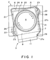
- Figure 1 is a top plan view illustrating a toner cartridge mounted on the mount and takes a removable position.
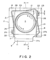
- Figure 2 is a top plan view of the same when the toner cartridge takes a toner discharge position.
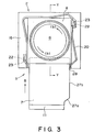
- Figure 3 is a top plan view in which the shutter takes the completely open position while the toner cartridge takes the toner discharge position.
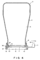
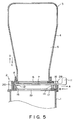
- Figure 4 is a sectional view of a toner cartridge.
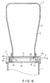
- Figure 5 is a sectional view taken along a line X-X in Figure 2.
- Figure 6 is a sectional view taken along a line Y-Y in Figure 3.
- Figure 7 is a sectional view taken along a line Z-Z in Figure 2.
- Figure 8 is a top plan view of a shutter plate.
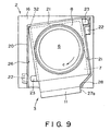
- Figure 9 is a top plan view of a toner cartridge according to another embodiment of the present invention which is in a removable position.
- Figure 10 is a top plan view of the same while the toner cartridge takes a toner discharge position.
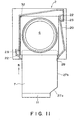
- Figure 11 is a top plan view of the same in which a shutter of the toner cartridge is completely opened, while the toner cartridge is placed in the toner discharging position.
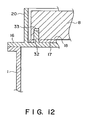
- Figure 12 is a sectional view taken along a line G-G of Figure 10.
- Figure 13 is a sectional view of a toner cartridge in a removable position.
- Figure 14 is the same view when the toner cartridge is at the discharge position.
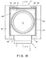
- Figure 15 is a top plan view of the toner cartridge of Figure 14.
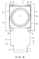
- Figure 16 is a top plan view of the toner cartridge in which the shutter is fully opened.
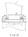
- Figure 17 is a front view of the cartridge of Figure 14.
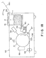
- Figure 18 shows an example of an image forming apparatus usable with the present invention.
- Figure 18 shows an electrophotographic apparatus usable with the present invention.
- an electrophotographic image forming apparatus 50 comprises an electrophotographic photosensitive member 51 rotatable in a direction indicated by an arrow.
- the photosensitive member 51 is first charged by a charger 52, and is exposed to image light by exposure device 53, so that an electrostatic latent image is formed.
- the electrostatic latent image is developed by a developing limit 54, which comprises a developing roller 55 rotatable in a direction indicated by an arrow.
- the developing roller 55 carries a developer D to supply it to the electrostatic latent image.
- the developer may be one component developer, or two component developer. In any event, the toner on the developing roller is deposited onto the electrostatic latent image to form a toner image.
- the toner image thus formed is transferred onto a transfer sheet 57 by a transfer charger 56, and the transferred image is fixed on the sheet 57 by a fixing device 58. After the image transfer operation, the photosensitive member 51 is cleaned by a cleaning device.
- the toner T is supplied from a toner storage container (hopper) 1 to the developing unit 54 by a feeding device 63 such as a screw conveyer or the like.
- the operator supplies the toner into the container 1 from a toner cartridge.
- the toner cartridge is mounted to a cartridge mount 2 provided at a top part of a hopper (toner storage container) 1.
- the toner cartridge mount 2 is usually covered with a cover 61.
- the cover 61 is rotatably supported on a shaft 62. When the cartridge is to be mounted to the mount 2, it is rotated to a position indicated by 61 manually by the operator to expose the mount 2.
- Figure 4 is a sectional view of a toner cartridge.
- the toner cartridge 3 comprises a container body 4 having a toner accommodation chamber 5 for accommodating toner to be supplied to the hopper 1, a shutter plate 7 for closing and opening the toner discharge opening 6, a shutter support 8 for slidably supporting the shutter plate 7.
- the shutter support 8 is securedly fixed to the container body 4 by screws 9.
- the shutter support 8, as shown in Figure 7, is provided with a shutter guide 10.
- the shutter plate 7 slides on the guide 10, and is rectilinearly reciprocable in a direction perpendicular to the toner discharge direction (downward) from the toner discharge opening 6.
- Designated by reference numerals 14 and 15 are elastic sealing member made of rubber, felt or the like to prevent the leakage of the toner between the shutter plate 7 and the shutter support 8, and between the container body 4 and the shutter support 8, respectively.
- a grip 11 is provided adjacent an end of the shutter plate 7 in the pulling direction, the operator grips the grip 11 to move the shutter plate 7 in directions A and B.
- a stopper projection 12 To the rear end of the shutter plate 7 in the pulling direction, there is provided a stopper projection 12.
- the stopper projection 18 abuts a front wall 13 of the shutter support 8 to prevent further motion of the shutter plate 7, thus preventing the shutter plate 7 from being pulled out of the support 8 ( Figure 6).
- the cartridge mount 2 comprises a base plate 16 fixed on the top of the hopper 1, and an elastic sealing member 17 of rubber, felt, synthetic resin material or the like, fixed on the base plate 16.
- the shutter support 8 of the cartridge 3 is slidably mounted on the top surface 18 of the elastic sealing member 17.
- the base plate 18 is provided with a toner receiving opening 19 through which the toner discharged through the toner discharging opening 3 of the toner cartridge 3 falls into the hopper 1.
- a wall plate 20 is fixed on and perpendicularly extended from the base plate 16.
- the wall plate 20, as shown in Figure 1 is provided with a guiding surface 21 for guiding the mounting and demounting of the toner cartridge relative to the cartridge mounting position of the cartridge mount 2.
- the motion of the toner cartridge 3 is guided in a direction substantially perpendicular to the cartridge mounting surface 18.
- the operator holds the container body 4 of the cartridge 3 by his hand, and lowers it in a direction C shown in Figure 5 along the guiding surface 21, by which the cartridge 3 is placed on the surface 18. On the other hand, by raising the cartridge 3 in a direction D along the guiding surface 21, the cartridge 3 is removed from the mount 2.
- Figures 1, 2 and 3 are top plan views of the toner cartridge mounted on the cartridge mount 2.
- the container body is omitted from the Figure.
- a projection 23 of the shutter support 8 is engaged into a recess 22 formed in the wall plate 20, by the above rotation ( Figure 2, and Figure 7 which is a sectional view taken along a line Z-Z of Figure 2).
- FIG 7 shows the top surface 24 of the projection 23 of the toner cartridge 3 in which the toner cartridge 3 is press-contacted to the top sealing surface 25 of the recess 22, by which the toner cartridge 3 is prevented from being removed upwardly from the cartridge mount 2.
- Figure 2 shows the state in which the toner cartridge 3 takes a toner discharge position for discharging the toner into the hopper by opening the toner discharge opening of the toner cartridge 3.
- the bottom surface of the shutter support 8 of the cartridge elastically compresses the sealing member 17 to improve the press-contact therebetween, so that the toner leakage from the contact portion between the cartridge 3 and the mount 2 can be further prevented.
- the projection 23 is formed in the toner cartridge 3, and the recess 22 is formed in the cartridge mount.
- the recess may be formed in the toner cartridge 3, and the projection may be formed in the toner cartridge, wherein they are engaged by rotation of the cartridge 3 in a direction a .
- the toner cartridge 3 is slidingly rotated in a direction a on the mount surface 18, by which the projection 23 is engaged into the recess 22, so that the cartridge 3 takes the toner discharge position as shown in Figure 2.
- three side surfaces of the shutter support 8 of the cartridge 3 are abutted to three stopping surfaces 26 formed on the wall plate 20, respectively. In this manner, further rotation of the toner cartridge in the direction a beyond the toner discharge position, is prohibited.
- a second portion of the side surface of the shutter support 8, contactable to the stopper surfaces 26, are different from a first position slidable relative to the guiding surface 21, and as will be understood from Figures 1 and 2, when the first portion is in contact with the guiding surface 21, the second portion is disengaged from the stop surfaces 26. On the other hand, when the second portion is in contact with the stopping surface 26, the first portion is out of contact with the guiding surface 21.
- the shutter plate 7 comprises a narrow portion 7a and a wide portion 7b having a width larger than that of the narrow portion 7a.
- the narrow portion 7a is disposed at a front side with respect to the pulling direction of the shutter plate 7. Therefore, an end of a front part of the shutter plate 7a is cut-away, as shown in Figure 8.
- the toner discharge opening 6 of the toner cartridge 3 is completely closed by the wide portion 7b of the shutter plate 7.
- the wide portion 7b is slidable engagement with the shutter support 8, and even when the wide portion 8b completely closes the shutter discharge opening 6, the narrow portion 7a projects out from the shutter support 8.
- the narrow portion 7a is provided with inclined stepped portion in the illustrated example, it may be a stepped portion perpendicular to a side surface 27b of the wide portion 7b.
- the grip 21 is fixed to an end of the narrow portion 7a.
- Figure 3 shows a state in which the shutter plate is pulled to a position at which the stopper projection 12 is abutted to the wall surface 13 of the shutter support.
- Figure 6 is a sectional view taken along a line Y-Y of Figure 3.
- the toner discharge opening 6 of the container body 4 of the toner cartridge is completely opened.
- the toner contained in the container body 4 falls by the gravity into the hopper 1 with the opening action of the opening 6.
- the opening 6 is completely opened, the toner in the container body 4 smoothly and quickly falls into the hopper 1.
- the toner cartridge 3 can not be removed from the mount, even if the operator erroneously tries to raise it. This is because the projection 23 of the toner cartridge is engaged into the recess 22 of the mount 2.
- the wall plate 20 of the cartridge mount 2 is provided with a limiting surface 28 faced to the pulling or pushing path of the shutter plate 7.
- the side surface 27b of the wide portion 7b of the shutter plate is opposed to the limiting surface 2B with or without small gap therebetween ( Figure 3).
- the toner cartridge 3 can not be returned to the cartridge mounting and demounting position from the toner discharge position, as long as the toner discharge opening 6 is not completely closed by the shutter plate 7. Therefore, it can be avoided that the cartridge is removed before the toner discharge opening is not completely closed with the result that the toner powder remaining in the container body leaks out and scanners out.
- the toner cartridge 3 is rotated slidingly in a direction a and b about an axis passing through a neighborhood of a center of the toner discharge opening 6, within an enclosure defined by wall 20 extended perpendicularly.
- a core rod is provided to improve the operativity in the rotation of the toner cartridge 3.
- the base plate 17 of the cartridge mount 2 is provided with a core rod 32 extended substantially perpendicularly therefrom.
- a hole 33 formed adjacent a corner of the shutter support 8 of the cartridge 3 receives the core rod 32.
- the cartridge 3 rotates in a direction c about the core rod 32 from the position of Figure 9 (mounting and demounting position) on the mount surface 3, to Figure 10 position (toner discharge position). Subsequently, the shutter plate 7 is pulled as shown in Figure 11 to permit toner discharge. Then, the shutter plate 7 is pushed in, and the cartridge is rotated in a direction d which is opposite from the direction c about the core rod 32, sliding on the mount surface 3, by which it is returned from Figure 10 position to Figure 9 position. In the Figure 9 position, the cartridge 3 can be demounted from the mount 2.
- the side surface 27b of the wide portion 7b of the shutter plate abuts the limiting surface 28 to prevent the rotation of the cartridge 3 from the toner discharging position to the cartridge mounting and demounting position, similarly to the foregoing embodiment.
- a pivot projection 34 is provided in the shutter support 8 of the toner cartridge 3 at an opposite side in the shutter plate pulling direction.
- the operator holds the toner cartridge 3 and lowers it in an inclined direction. As shown in Figure 13, the pivot projection 34 is engaged into the recess 35 of the wall plate 20 of the cartridge mount 2.
- the operator rotates the cartridge 3 in a direction e about the pivot projection 34.
- the bottom surface of the shutter support 8 is contacted to the top surface of the cartridge mount surface 18 (elastic sealing member 17) of the mount 2.
- the movement is guided by the sliding between the guiding surface 29 of the wall plate 20 and a side surface of the shutter support 8.
- the cartridge position of Figure 13 is a cartridge mounting and demounting position, and the position shown in Figure 14 is a toner discharging position.
- Figure 15 is a top plan view in the state shown in Figure 14, and Figure 17 is a front view in the same state.
- a pair of channel like projections 36 are provided with a space therebetween slightly larger than a width of a narrow portion 7a of the shutter plate 7, in a front portion of the wall plate 20 of the cartridge mount 2.
- width of shutter plate is a dimension of the shutter plate surface effective to close the toner discharge opening, measured in a direction perpendicular to the shutter plate pulling or pushing direction.
- a side surface of the shutter plate is an end surface of the shutter plate in the width direction.
- the top surface of the shutter plate is a surface of the shutter plate effective to close the shutter discharge opening.
Abstract
Description
Claims (26)
- A toner container for supplying toner to an image forming apparatus having a container mounting portion (2) for receivably mounting said container with a discharge opening (6) of said container facing downwardly toward a toner receiving opening formed in a mounting surface (10) of said container mounting portion (2), and a toner accommodating portion (1) into which the toner receiving opening of the container mounting portion (2) leads, the container mounting portion further comprising dismounting preventing means (22) engageable with the toner container (3) and wherein said toner container (3) is mountable on said container mounting portion (2) so as to be rotatable about an axis substantially perpendicular to the mounting surface (18) between a mounting position for mounting and dismounting said toner container and a toner supply position for supplying toner to said toner accommodating portion (1); said toner container (3) including a container body (4) for containing toner, and engaging means (23) which becomes engaged with the said dismounting preventing means (22) of said mounting portion (2) when said toner container is rotated from the mounting position to the toner supply position to prevent dismounting of said toner container; characterised in that at a mounting region adjacent the toner discharge opening (6) the toner container is generally rectangular when viewed in a direction parallel to said axis.
- A toner container according to claim 10, wherein the first retaining means is a projection (23) extending from the rectangular region.
- A toner container according to claim 11, wherein the projection (23) is provided adjacent a corner of said mounting region.
- A toner container according to claim 12, wherein a said projection (23) is provided at each of two diagonally opposite portions of said mounting region.
- A toner container according to claim 10, wherein the first retaining means is a recess formed in the said mounting region.
- A toner container according to any of claims 1 to 4, wherein the discharge opening (6) of the toner container is formed in a rectangular end surface of the mounting region (8) of the toner container.
- A toner container according to claim 6, wherein said mounting region (8) further comprises four side surfaces extending perpendicularly from the edges of said rectangular end surface.
- A toner container according to claim 7, wherein said engaging means (23) is a projection extending from one of the said side surfaces in a direction substantially parallel with the plane of the end surface.
- A toner container according to claim 8, wherein two of said projections (23) extend from two respective side surfaces.
- A toner container according to claim 9, wherein said projections (23) extend from respective opposite side surfaces.
- A toner container according to any of claims 8 to 10, wherein the said projections extend from the respective side surfaces adjacent to corners of the mounting region (8).
- A toner container according to claim 11, wherein the projections (23) extend from diagonally opposing corners of the mounting region (8).
- A toner supply apparatus for an image forming apparatus comprising:a toner container (3) including a container body (4) for containing toner and having a toner discharge opening (6),a container mounting portion (2) having a mounting surface (18) in which is formed a receiving opening for receiving toner from said toner container (3), said container mounting portion (2) receivably mounting said toner container with the discharge opening (3) facing downward toward said receiving opening; anda toner accommodating portion (1) into which the receiving opening of the container mounting portion leads;wherein when said toner container (3) is mountable on said container mounting portion (2) so as to be rotatable about an axis substantially perpendicular to the mounting surface (18) between a mounting position for mounting and dismounting said toner container and a toner supply position for supplying toner to said toner storage unit; andwherein said container mounting portion (2) has a dismounting preventing portion (22) which becomes engaged with said toner container when said toner container is rotated from the mounting position to the toner supply position to prevent dismounting of said toner container; characterised in that at a mounting region adjacent the toner discharge opening (6) the toner container is generally rectangular when viewed in a direction parallel to said axis.
- An apparatus according to claim 13, wherein the toner container (3) has a mounting region (8) comprising a rectangular end surface in which the discharge opening (6) is formed, and four side surfaces extending perpendicularly from respective edges of the end surface.
- An apparatus according to claim 13 or claim 14, wherein the container mounting portion (2) comprises a guiding surface (21) for engaging a side surface of said mounting region when the toner container is in the mounting position for guiding movement of said toner container (3) in a direction of said axis.
- An apparatus according to claim 15, wherein the guiding surface (21) comprises first and second guiding surface portions in mutually perpendicular planes for engaging adjacent side surfaces of said rectangular region.
- An apparatus according to any of claims 13 to 16 wherein the mounting portion (2) comprises a stop surface (26) extending perpendicularly to the mounting surface (18) and adapted to engage a side surface of said mounting region of the toner container (3) when said toner container (3) is in the toner supply position.
- An apparatus according to claim 17, wherein the stop surface (26) comprises first and second stop surface portions in mutually perpendicular planes, the first and second stop surface portions engaging adjacent side surfaces of said mounting region when the toner container (3) is in the toner supply position.
- An apparatus according to any of claims 13 to 18, wherein said toner container (3) includes a projection (23) engageable with a recess (22) of said dismounting preventing portion by rotation of said toner container to the toner supply position, thereby to prevent dismounting of said toner container.
- An apparatus according to claim 19 wherein a said projection (23) is provided at each of two diagonally opposite portions of said mounting region of said toner container.
- An apparatus according to claim 19, wherein said recess (22) is formed in said stop surface (26).
- An apparatus according to any of claims 13 to 18 wherein said toner container (3) includes a recess engageable with a projection of said container mounting portion by rotation of said toner container to the toner supply position, thereby to prevent dismounting of said toner container.
- A mounting element (8) for a toner container (3) according to any of claims 12 to 18, comprising a circular mounting interface (9) for fixing the mounting element (8) to a circular neck of a toner container body (4), a mounting region having a rectangular end surface in which a toner discharge opening is formed, and further including first retaining means (23) cooperable with second retaining means (22) of the toner mounting portion (2).
- A mounting element (8) according to claim 23 wherein the first retaining means (23) is a projection.
- A mounting element (8) according to claim 24, wherein the projection (23) is provided adjacent a corner of said mounting region of said mounting element.
- A mounting element (8) according to claim 25, wherein a respective projection (23) is provided at each of two diagonally opposite portions of said rectangular region.
Applications Claiming Priority (4)
| Application Number | Priority Date | Filing Date | Title |
|---|---|---|---|
| JP155303/93 | 1993-06-25 | ||
| JP5155303A JP2887046B2 (en) | 1993-06-25 | 1993-06-25 | Toner replenishing device and toner cartridge used for it |
| JP15530393 | 1993-06-25 | ||
| EP94304635A EP0631206B1 (en) | 1993-06-25 | 1994-06-27 | Toner supply apparatus |
Related Parent Applications (1)
| Application Number | Title | Priority Date | Filing Date |
|---|---|---|---|
| EP94304635A Division EP0631206B1 (en) | 1993-06-25 | 1994-06-27 | Toner supply apparatus |
Publications (3)
| Publication Number | Publication Date |
|---|---|
| EP0892321A2 true EP0892321A2 (en) | 1999-01-20 |
| EP0892321A3 EP0892321A3 (en) | 1999-10-20 |
| EP0892321B1 EP0892321B1 (en) | 2002-05-15 |
Family
ID=15602957
Family Applications (3)
| Application Number | Title | Priority Date | Filing Date |
|---|---|---|---|
| EP98203218A Expired - Lifetime EP0892321B1 (en) | 1993-06-25 | 1994-06-27 | Toner container and toner supply apparatus |
| EP94304635A Expired - Lifetime EP0631206B1 (en) | 1993-06-25 | 1994-06-27 | Toner supply apparatus |
| EP99201155A Expired - Lifetime EP0940732B8 (en) | 1993-06-25 | 1994-06-27 | Toner container |
Family Applications After (2)
| Application Number | Title | Priority Date | Filing Date |
|---|---|---|---|
| EP94304635A Expired - Lifetime EP0631206B1 (en) | 1993-06-25 | 1994-06-27 | Toner supply apparatus |
| EP99201155A Expired - Lifetime EP0940732B8 (en) | 1993-06-25 | 1994-06-27 | Toner container |
Country Status (6)
| Country | Link |
|---|---|
| US (1) | US5593068A (en) |
| EP (3) | EP0892321B1 (en) |
| JP (1) | JP2887046B2 (en) |
| DE (3) | DE69430642T2 (en) |
| ES (2) | ES2176901T3 (en) |
| SG (2) | SG116405A1 (en) |
Families Citing this family (22)
| Publication number | Priority date | Publication date | Assignee | Title |
|---|---|---|---|---|
| JP3658081B2 (en) * | 1996-03-27 | 2005-06-08 | キヤノン株式会社 | Toner supply container |
| JP3408166B2 (en) | 1997-09-30 | 2003-05-19 | キヤノン株式会社 | Toner supply container and electrophotographic image forming apparatus |
| JP3450757B2 (en) | 1998-09-22 | 2003-09-29 | キヤノン株式会社 | Toner supply container |
| JP3445202B2 (en) | 1999-03-29 | 2003-09-08 | キヤノン株式会社 | Toner supply container |
| US6438328B1 (en) | 2000-11-08 | 2002-08-20 | Xerox Corporation | Reversible shutter lockout feature |
| DE10057371A1 (en) * | 2000-11-18 | 2002-05-29 | Dietrich Troeltsch Gmbh & Co G | Cap for a toner bottle |
| US6907208B2 (en) * | 2002-10-25 | 2005-06-14 | Michael E. Bausch | Developer cartridge including sealing gasket |
| US6868988B2 (en) * | 2003-02-28 | 2005-03-22 | Nestec S.A. | Containers of flowable substance adapted for connecting to dispensing devices of a beverage or food dispensing machine |
| JP4693393B2 (en) * | 2003-11-19 | 2011-06-01 | キヤノン株式会社 | Developer supply device |
| JP4674478B2 (en) * | 2005-03-03 | 2011-04-20 | 富士ゼロックス株式会社 | Toner cartridge |
| US8190068B2 (en) * | 2005-03-04 | 2012-05-29 | Canon Kabushiki Kaisha | Developer supply container with mounting attitude regulation and drive receiving member rotation suppression features |
| SI3081991T1 (en) | 2005-03-04 | 2018-11-30 | Canon Kabushiki Kaisha | Toner supply container |
| US8579162B2 (en) * | 2010-04-14 | 2013-11-12 | 3M Innovative Properties Company | Enclosure for use with a gravity fed fluid dispensing system |
| JP6083954B2 (en) | 2011-06-06 | 2017-02-22 | キヤノン株式会社 | Developer supply container and developer supply system |
| JP6016088B2 (en) * | 2012-08-10 | 2016-10-26 | 株式会社リコー | Shutter mechanism and image forming apparatus |
| AT515274B1 (en) * | 2013-12-20 | 2017-10-15 | Hans Georg Hagleitner | container |
| SG11202007457PA (en) * | 2018-02-05 | 2020-09-29 | Ecolab Usa Inc | Packaging and docking system for non-contact chemical dispensing |
| KR20200025354A (en) * | 2018-08-30 | 2020-03-10 | 휴렛-팩커드 디벨롭먼트 컴퍼니, 엘.피. | Toner refill cartridge with extendable plunger |
| WO2020163470A1 (en) | 2019-02-05 | 2020-08-13 | Ecolab Usa Inc. | Packaging and docking system for non-contact chemical dispensing |
| JP2020158911A (en) * | 2019-03-26 | 2020-10-01 | セイコーエプソン株式会社 | Additive storage tool |
| WO2021065832A1 (en) * | 2019-09-30 | 2021-04-08 | キヤノン株式会社 | Image forming device |
| CN114200799A (en) * | 2020-09-17 | 2022-03-18 | 珠海新钰科技有限公司 | Combined selenium drum capable of circularly replacing powder box |
Citations (4)
| Publication number | Priority date | Publication date | Assignee | Title |
|---|---|---|---|---|
| EP0098081A2 (en) * | 1982-06-23 | 1984-01-11 | Konica Corporation | Developer incoming device in electrostatic reproduding apparatus |
| EP0431615A2 (en) * | 1989-12-08 | 1991-06-12 | Mita Industrial Co. Ltd. | Cartridge unit |
| US5074344A (en) * | 1990-10-22 | 1991-12-24 | Eastman Kodak Company | Toner container and latchable cover |
| US5089854A (en) * | 1990-02-19 | 1992-02-18 | Shozo Kaieda | Apparatus for supplementing developing agent into image forming machine |
Family Cites Families (10)
| Publication number | Priority date | Publication date | Assignee | Title |
|---|---|---|---|---|
| US3581949A (en) * | 1968-11-12 | 1971-06-01 | Reynolds Tobacco Co R | Controlled volumetric feeding apparatus |
| US3915208A (en) * | 1973-07-24 | 1975-10-28 | Inforex | Toner supply apparatus with replenishing container |
| JPS57211176A (en) * | 1981-06-23 | 1982-12-24 | Hitachi Metals Ltd | Toner cartridge |
| US4456154A (en) * | 1982-08-16 | 1984-06-26 | Xerox Corporation | Toner loading cartridge |
| US4878603B1 (en) * | 1984-01-09 | 1994-11-08 | Ricoh Kk | Toner replenishing device |
| US4752807A (en) * | 1986-12-22 | 1988-06-21 | Eastman Kodak Company | Apparatus for adding toner to an electrographic development station |
| JPH0738089B2 (en) * | 1988-11-30 | 1995-04-26 | 三田工業株式会社 | Developer container |
| US4942432A (en) * | 1989-06-28 | 1990-07-17 | Eastman Kodak Company | Apparatus for adding toner to an electrostatographic development station |
| JP2578228B2 (en) * | 1989-12-26 | 1997-02-05 | 沖電気工業株式会社 | Toner developing device and toner cartridge attaching / detaching method |
| US5261568A (en) * | 1992-02-14 | 1993-11-16 | Eastman Kodak Company | Apparatus for storing and dispensing pigmented marking particles |
-
1993
- 1993-06-25 JP JP5155303A patent/JP2887046B2/en not_active Expired - Lifetime
-
1994
- 1994-06-27 SG SG1999004378A patent/SG116405A1/en unknown
- 1994-06-27 EP EP98203218A patent/EP0892321B1/en not_active Expired - Lifetime
- 1994-06-27 EP EP94304635A patent/EP0631206B1/en not_active Expired - Lifetime
- 1994-06-27 ES ES98203218T patent/ES2176901T3/en not_active Expired - Lifetime
- 1994-06-27 ES ES99201155T patent/ES2177196T3/en not_active Expired - Lifetime
- 1994-06-27 DE DE69430642T patent/DE69430642T2/en not_active Expired - Lifetime
- 1994-06-27 EP EP99201155A patent/EP0940732B8/en not_active Expired - Lifetime
- 1994-06-27 US US08/265,937 patent/US5593068A/en not_active Expired - Lifetime
- 1994-06-27 SG SG9608883-6A patent/SG166659A1/en unknown
- 1994-06-27 DE DE69430680T patent/DE69430680T2/en not_active Expired - Lifetime
- 1994-06-27 DE DE69426547T patent/DE69426547T2/en not_active Expired - Lifetime
Patent Citations (4)
| Publication number | Priority date | Publication date | Assignee | Title |
|---|---|---|---|---|
| EP0098081A2 (en) * | 1982-06-23 | 1984-01-11 | Konica Corporation | Developer incoming device in electrostatic reproduding apparatus |
| EP0431615A2 (en) * | 1989-12-08 | 1991-06-12 | Mita Industrial Co. Ltd. | Cartridge unit |
| US5089854A (en) * | 1990-02-19 | 1992-02-18 | Shozo Kaieda | Apparatus for supplementing developing agent into image forming machine |
| US5074344A (en) * | 1990-10-22 | 1991-12-24 | Eastman Kodak Company | Toner container and latchable cover |
Also Published As
| Publication number | Publication date |
|---|---|
| JPH0772725A (en) | 1995-03-17 |
| DE69430642T2 (en) | 2002-10-17 |
| EP0631206A3 (en) | 1996-04-24 |
| EP0892321A3 (en) | 1999-10-20 |
| EP0892321B1 (en) | 2002-05-15 |
| EP0631206B1 (en) | 2001-01-10 |
| SG116405A1 (en) | 2005-11-28 |
| EP0940732A3 (en) | 2000-01-19 |
| DE69426547T2 (en) | 2001-07-05 |
| EP0940732A2 (en) | 1999-09-08 |
| EP0940732B8 (en) | 2002-10-09 |
| US5593068A (en) | 1997-01-14 |
| ES2176901T3 (en) | 2002-12-01 |
| ES2177196T3 (en) | 2002-12-01 |
| DE69430680D1 (en) | 2002-06-27 |
| DE69426547D1 (en) | 2001-02-15 |
| JP2887046B2 (en) | 1999-04-26 |
| DE69430642D1 (en) | 2002-06-20 |
| EP0940732B1 (en) | 2002-05-22 |
| SG166659A1 (en) | 2010-12-29 |
| DE69430680T2 (en) | 2002-10-17 |
| EP0631206A2 (en) | 1994-12-28 |
Similar Documents
| Publication | Publication Date | Title |
|---|---|---|
| EP0892321A2 (en) | Toner container | |
| EP0843233B1 (en) | Toner supply cartridge and image forming apparatus | |
| US5095335A (en) | Copier with retractable charging unit to prevent damage to drum when removing process cartridge | |
| US5870652A (en) | Developer cartridge featuring a developer replenishment hole and removable cap having a gripping member for sealing the hole and a remanufacturing method using the same | |
| US4583832A (en) | Developing device | |
| EP0578340B1 (en) | Developing device | |
| JP3492856B2 (en) | Image forming device | |
| US5289243A (en) | Installation and removal structure of a developing unit and a toner cartridge in an image forming apparatus | |
| US4860056A (en) | Sealable toner recovery box for an image forming machine | |
| US6934492B2 (en) | Toner supply container, image formation unit and image forming apparatus | |
| EP0686892A2 (en) | Image forming apparatus having toner replenishment device | |
| JPH03175471A (en) | Developing device of electrphotographic recording device | |
| JP3993976B2 (en) | Toner bottle, toner supply mechanism, and image forming apparatus | |
| JPH1195638A (en) | Image forming unit | |
| JP3502732B2 (en) | Image forming device | |
| JPH0943954A (en) | Toner cartridge and toner supply device with same | |
| JP2912077B2 (en) | Electrophotographic equipment | |
| JPH07175398A (en) | Toner cartridge, toner replenishment mechanism, toner replenishment method and image forming device | |
| JP2991265B2 (en) | Electrophotographic equipment | |
| JPH11109737A (en) | Toner replenishing mechanism | |
| JP3599959B2 (en) | Image forming device | |
| JP2678379B2 (en) | Image forming device | |
| JP3165746B2 (en) | Developer cartridge | |
| JP2862284B2 (en) | Developing device | |
| JP2810915B2 (en) | Toner cartridge |
Legal Events
| Date | Code | Title | Description |
|---|---|---|---|
| PUAI | Public reference made under article 153(3) epc to a published international application that has entered the european phase |
Free format text: ORIGINAL CODE: 0009012 |
|
| AC | Divisional application: reference to earlier application |
Ref document number: 631206 Country of ref document: EP |
|
| AK | Designated contracting states |
Kind code of ref document: A2 Designated state(s): CH DE ES FR GB IT LI NL |
|
| RBV | Designated contracting states (corrected) |
Designated state(s): CH DE ES FR GB IT LI NL |
|
| PUAL | Search report despatched |
Free format text: ORIGINAL CODE: 0009013 |
|
| RTI1 | Title (correction) |
Free format text: TONER CONTAINER |
|
| AK | Designated contracting states |
Kind code of ref document: A3 Designated state(s): CH DE ES FR GB IT LI NL |
|
| 17P | Request for examination filed |
Effective date: 20000329 |
|
| 17Q | First examination report despatched |
Effective date: 20001120 |
|
| GRAG | Despatch of communication of intention to grant |
Free format text: ORIGINAL CODE: EPIDOS AGRA |
|
| RTI1 | Title (correction) |
Free format text: TONER CONTAINER AND TONER SUPPLY APPARATUS |
|
| GRAG | Despatch of communication of intention to grant |
Free format text: ORIGINAL CODE: EPIDOS AGRA |
|
| GRAG | Despatch of communication of intention to grant |
Free format text: ORIGINAL CODE: EPIDOS AGRA |
|
| GRAH | Despatch of communication of intention to grant a patent |
Free format text: ORIGINAL CODE: EPIDOS IGRA |
|
| GRAA | (expected) grant |
Free format text: ORIGINAL CODE: 0009210 |
|
| AC | Divisional application: reference to earlier application |
Ref document number: 631206 Country of ref document: EP |
|
| AK | Designated contracting states |
Kind code of ref document: B1 Designated state(s): CH DE ES FR GB IT LI NL |
|
| REG | Reference to a national code |
Ref country code: CH Ref legal event code: NV Representative=s name: BOVARD AG PATENTANWAELTE Ref country code: GB Ref legal event code: FG4D Ref country code: CH Ref legal event code: EP |
|
| REF | Corresponds to: |
Ref document number: 69430642 Country of ref document: DE Date of ref document: 20020620 |
|
| ET | Fr: translation filed | ||
| REG | Reference to a national code |
Ref country code: ES Ref legal event code: FG2A Ref document number: 2176901 Country of ref document: ES Kind code of ref document: T3 |
|
| PLBE | No opposition filed within time limit |
Free format text: ORIGINAL CODE: 0009261 |
|
| STAA | Information on the status of an ep patent application or granted ep patent |
Free format text: STATUS: NO OPPOSITION FILED WITHIN TIME LIMIT |
|
| 26N | No opposition filed |
Effective date: 20030218 |
|
| REG | Reference to a national code |
Ref country code: CH Ref legal event code: PFA Owner name: CANON KABUSHIKI KAISHA Free format text: CANON KABUSHIKI KAISHA#30-2, 3-CHOME, SHIMOMARUKO, OHTA-KU#TOKYO (JP) -TRANSFER TO- CANON KABUSHIKI KAISHA#30-2, 3-CHOME, SHIMOMARUKO, OHTA-KU#TOKYO (JP) |
|
| PGFP | Annual fee paid to national office [announced via postgrant information from national office to epo] |
Ref country code: CH Payment date: 20120618 Year of fee payment: 19 Ref country code: DE Payment date: 20120630 Year of fee payment: 19 Ref country code: NL Payment date: 20120620 Year of fee payment: 19 |
|
| PGFP | Annual fee paid to national office [announced via postgrant information from national office to epo] |
Ref country code: GB Payment date: 20120626 Year of fee payment: 19 |
|
| PGFP | Annual fee paid to national office [announced via postgrant information from national office to epo] |
Ref country code: IT Payment date: 20120611 Year of fee payment: 19 |
|
| PGFP | Annual fee paid to national office [announced via postgrant information from national office to epo] |
Ref country code: ES Payment date: 20120626 Year of fee payment: 19 Ref country code: FR Payment date: 20120712 Year of fee payment: 19 |
|
| REG | Reference to a national code |
Ref country code: NL Ref legal event code: V1 Effective date: 20140101 |
|
| REG | Reference to a national code |
Ref country code: CH Ref legal event code: PL |
|
| GBPC | Gb: european patent ceased through non-payment of renewal fee |
Effective date: 20130627 |
|
| REG | Reference to a national code |
Ref country code: DE Ref legal event code: R119 Ref document number: 69430642 Country of ref document: DE Effective date: 20140101 |
|
| REG | Reference to a national code |
Ref country code: FR Ref legal event code: ST Effective date: 20140228 |
|
| PG25 | Lapsed in a contracting state [announced via postgrant information from national office to epo] |
Ref country code: DE Free format text: LAPSE BECAUSE OF NON-PAYMENT OF DUE FEES Effective date: 20140101 Ref country code: LI Free format text: LAPSE BECAUSE OF NON-PAYMENT OF DUE FEES Effective date: 20130630 Ref country code: NL Free format text: LAPSE BECAUSE OF NON-PAYMENT OF DUE FEES Effective date: 20140101 Ref country code: GB Free format text: LAPSE BECAUSE OF NON-PAYMENT OF DUE FEES Effective date: 20130627 Ref country code: CH Free format text: LAPSE BECAUSE OF NON-PAYMENT OF DUE FEES Effective date: 20130630 |
|
| PG25 | Lapsed in a contracting state [announced via postgrant information from national office to epo] |
Ref country code: IT Free format text: LAPSE BECAUSE OF NON-PAYMENT OF DUE FEES Effective date: 20130627 Ref country code: FR Free format text: LAPSE BECAUSE OF NON-PAYMENT OF DUE FEES Effective date: 20130701 |
|
| REG | Reference to a national code |
Ref country code: ES Ref legal event code: FD2A Effective date: 20140707 |
|
| PG25 | Lapsed in a contracting state [announced via postgrant information from national office to epo] |
Ref country code: ES Free format text: LAPSE BECAUSE OF NON-PAYMENT OF DUE FEES Effective date: 20130628 |