EP0891856B1 - A bending table - Google Patents
A bending table Download PDFInfo
- Publication number
- EP0891856B1 EP0891856B1 EP98304814A EP98304814A EP0891856B1 EP 0891856 B1 EP0891856 B1 EP 0891856B1 EP 98304814 A EP98304814 A EP 98304814A EP 98304814 A EP98304814 A EP 98304814A EP 0891856 B1 EP0891856 B1 EP 0891856B1
- Authority
- EP
- European Patent Office
- Prior art keywords
- arms
- table according
- arm
- bending
- bending table
- Prior art date
- Legal status (The legal status is an assumption and is not a legal conclusion. Google has not performed a legal analysis and makes no representation as to the accuracy of the status listed.)
- Expired - Lifetime
Links
Images


Classifications
-
- B—PERFORMING OPERATIONS; TRANSPORTING
- B29—WORKING OF PLASTICS; WORKING OF SUBSTANCES IN A PLASTIC STATE IN GENERAL
- B29C—SHAPING OR JOINING OF PLASTICS; SHAPING OF MATERIAL IN A PLASTIC STATE, NOT OTHERWISE PROVIDED FOR; AFTER-TREATMENT OF THE SHAPED PRODUCTS, e.g. REPAIRING
- B29C53/00—Shaping by bending, folding, twisting, straightening or flattening; Apparatus therefor
- B29C53/02—Bending or folding
- B29C53/08—Bending or folding of tubes or other profiled members
- B29C53/083—Bending or folding of tubes or other profiled members bending longitudinally, i.e. modifying the curvature of the tube axis
-
- B—PERFORMING OPERATIONS; TRANSPORTING
- B29—WORKING OF PLASTICS; WORKING OF SUBSTANCES IN A PLASTIC STATE IN GENERAL
- B29K—INDEXING SCHEME ASSOCIATED WITH SUBCLASSES B29B, B29C OR B29D, RELATING TO MOULDING MATERIALS OR TO MATERIALS FOR MOULDS, REINFORCEMENTS, FILLERS OR PREFORMED PARTS, e.g. INSERTS
- B29K2027/00—Use of polyvinylhalogenides or derivatives thereof as moulding material
- B29K2027/06—PVC, i.e. polyvinylchloride
-
- B—PERFORMING OPERATIONS; TRANSPORTING
- B29—WORKING OF PLASTICS; WORKING OF SUBSTANCES IN A PLASTIC STATE IN GENERAL
- B29L—INDEXING SCHEME ASSOCIATED WITH SUBCLASS B29C, RELATING TO PARTICULAR ARTICLES
- B29L2031/00—Other particular articles
- B29L2031/001—Profiled members, e.g. beams, sections
- B29L2031/003—Profiled members, e.g. beams, sections having a profiled transverse cross-section
- B29L2031/005—Profiled members, e.g. beams, sections having a profiled transverse cross-section for making window frames
Definitions
- THIS INVENTION concerns a bending table upon which lengths of plastics material rendered flexible by heating, may be set to determine a desired curvature thereof and applies particularly to a table for bending UPVC sections to form a decorative arch for window and door frames.
- Lengths of uPVC section are rendered flexible by heating the profile to approximately 140°C in an oven. It can then be shaped as desired and allowed to cool down to room temperature whereupon the section will retain the required shape.
- this process is carried out on a table containing a number of angularly spaced straight slots extending radially from a central position, and a similar number of movable bobbins which are adjustable in position along the slots thus to provide a bearing surface to determine the required shape for the section.
- a flexible former strip is first placed around the pre-positioned bobbins and then the heated section is bent around the former and clamped in position until cool.
- the provision of a slotted surface in the table tends to mark the underside of the softened section and so to overcome this problem it has been necessary to provide a pre-shaped arcuate flat strip of hardboard or the like which is placed over the slots around the bobbins and upon which the section rests while cooling. This necessitates the provision of a large number of such strips to accommodate every shape and curvature to be formed.
- a plain table top is provided with a number of alternative and selectable adaptor platforms each having a plurality of slotted guides extendible radially outwards from the adaptor and arranged to engage a slotted former around which the desired section may be bent.
- a bending table comprising a table top, and a plurality of arms extending radially across the table top from a supporting member fixed with respect to the table top, at least some of said arms being adjustable in length or interchangeable, each arm having a bearing surface at its free end against which a flexible elongate work piece may be located; characterised in that the angle subtended by the or at least one pair of adjacent arms is adjustable.
- a bending table comprising a table top, and a plurality of arms extending across the table top from a supporting member fixed with respect to the table top, at least some of said arms being adjustable in length or interchangeable, each arm having a bearing member at its free end against which a flexible elongate work piece may be located; characterised in that the bearing members and the table surface are mutually magnetically attractive.
- Fig. 1 illustrates a bending table 1 having a plain unslotted table top preferably of polished stainless steel upon which radial and linear arched shaped window sections may be produced.
- the table surface may comprise a thin plastics laminate 1a having a surface finish upon which a length of softened uPVC section may be placed without adversely affecting the under surface of the section.
- Beneath the thin laminate, and stainless steel in one embodiment, is a wooden base mounted on legs to present a working surface at an operator's waist level.
- a radial positioning system as illustrated in Figs. 1 to 4 consists of a central spindle 4 having three independently rotating layers 4A, 4B and 4C.
- the spindle 4 may be positioned at any position along a slotted location strip 16 fixed along the centre line of the table 1.
- Each layer of the spindle defines a circumferential series of radially extending apertures 13 each adapted to receive one end of a radial arm comprising an elongate hollow sleeve 6.
- a number of such sleeves are provided, each removably retained within its associated aperture 13 by a spring clamp 13a.
- a rod 7 is telescopically slidable within each rod 6 and adjustably fixed by a quick release catch 20 thus to determine, within a certain range, the effective length of each radially extending sleeve and rod 6, 7. Additional extension pieces may be attached to the rods 7 to extend their lengths further if necessary.
- Each rod 7 carries a telescopically extendible or flexible outer sheath 21.
- each rod 17 Mounted fixedly on the outer end of each rod 17 is a bobbin 3 presenting a bearing surface, 22 and having an electromagnet 23 thus to be magnetically attracted to the surface 22 of the bending table 1.
- An upper part 24 of each bobbin carries toggle clamps 25 for attachment thereto of a former strip 26.
- a quick release spring clamp 27 enables a part 3a of each or some of the bobbins to be raised and lowered for adjustment with respect to the table surface, the former strip 26 and the heated section to be formed.
- the bobbin alternatively may be attracted to the table by a permanent magnet.
- each separately rotatable layer of the spindle 4 may carry a plurality of radial arms and because the layers are independently rotatable it is possible either to spread the bobbins 3 evenly around a substantially semi-circular shape as illustrated or alternatively to group two or more of them closely together to produce acute bends as will become evident.
- a central core member 14 of the central spindle 4 has an upper flange 12 and a bottom spigot 12a which is threadedly engaged in an anchor block 12b captively located on the inverted T-sectioned slot of strip 16.
- anchor block 12b captively located on the inverted T-sectioned slot of strip 16.
- a radial arm 8 Permanently rotatable relative to upper flange 12 in a bearing 15, on a column 15a is a radial arm 8 which is radially extendible relative to column 15a and carries a pointer or stylus 8a.
- the position of each bobbin 3 around a semi-circular arc may be determined and set without having to measure the radial extent of each bobbin arm separately.
- a plurality of telescopically extendible arms 17 mounted on the table and adjustably mounted on slotted strip 16, a plurality of telescopically extendible arms 17.
- a so-called fence 18 which may be similarly magnetically attracted to the table top and thus forms a straight edge along which a former and then a straight length of uPVC section may be positioned.
- the fences 18 may extend along the remaining length of the table, where a further radial positioning system may be provided as shown at the right hand end of Fig. 1. This may extend beyond a semi circle.
- a linear positioning system may incorporate an aligned series of extendible arms 17 attached along the centre strip 16 of the table.
- the strip may have two layers of receiving apertures in which the arms 17 may be located.
- Such arms may have bobbins attached to their free ends and so may be used in a manner similar to the radial positioning system described in relation to Figs. 1 and 2 and by using a template to position the bobbins, it is possible then to apply a former strip and a heated length of uPVC section to form a shallow arch of large and varying radius such as illustrated in Fig. 5D.
- independent, freely positionable and magnetically attractive bobbins 30 and fences 31 may be used on the table to retain the uPVC profile strips 32.
- Figs. 4A to 4D and 5D to 5D illustrate various forms of shaped section which may be produced using a bending table made in accordance with the invention.
- This wide variety of different shapes is easily attainable in view of the infinitely variable nature of the arms supporting the bobbins and fences. Such variation cannot be achieved on a slotted table or a table having a fixed shape of adaptor.
- Embodiments of the invention may include both radial and linear positioning systems as illustrated in Fig. 1 or one or other of such systems alone.
- the bobbins, fences and table surface have been described as being magnetically attractive in order to provide adequate support and prevent movement of the bobbins on the rods. This may be achieved by having the table top earthed and providing a supply of 12V +ve to electromagnets established in each bobbin and fence, or vice versa.
- the magnets may be permanent, or in some instances no magnetic attraction may be needed if there is sufficient rigidity in the structure to withstand any tendency for movement created when the former strip and section are placed around the structure. If electro-magnets are used a control or switching system may permit the user to select certain rows of the system to be magnetically active.
- any curved shape can be produced within the dimensions of the table by setting the bobbin positions as required to produce either a straight length or a curved shape with widely differing and varying curvatures. Setting up the table is a rapid and straight forward operation since no slots or clamped bobbins are required and the radial length of each arm for a curved profile is readily set by the rotating arm 8 with stylus 8a.
- Each arm 6, 17 is easily removed from the spindle 4 (or the slotted strip 16).
- the arms may be interchanged at will to produce the required curvature, the arms being thus universally adjustable to produce non-uniform shapes.
- the arms 6 alternatively may be threadedly located in apertures 13 or by a radial screw accessible by an Allen key introduced through an aperture in the top of the spindle.
- a bending table made in accordance with the invention is adaptable to produce uPVC section of any shape and configuration within the bounds of the table, a feature which cannot be achieved with any currently available conventional bending table.
Landscapes
- Engineering & Computer Science (AREA)
- Mechanical Engineering (AREA)
- Shaping Of Tube Ends By Bending Or Straightening (AREA)
- Extensible Doors And Revolving Doors (AREA)
Description
- THIS INVENTION concerns a bending table upon which lengths of plastics material rendered flexible by heating, may be set to determine a desired curvature thereof and applies particularly to a table for bending UPVC sections to form a decorative arch for window and door frames.
- Lengths of uPVC section are rendered flexible by heating the profile to approximately 140°C in an oven. It can then be shaped as desired and allowed to cool down to room temperature whereupon the section will retain the required shape.
- Conventionally, this process is carried out on a table containing a number of angularly spaced straight slots extending radially from a central position, and a similar number of movable bobbins which are adjustable in position along the slots thus to provide a bearing surface to determine the required shape for the section. Usually, a flexible former strip is first placed around the pre-positioned bobbins and then the heated section is bent around the former and clamped in position until cool. Unfortunately, the provision of a slotted surface in the table tends to mark the underside of the softened section and so to overcome this problem it has been necessary to provide a pre-shaped arcuate flat strip of hardboard or the like which is placed over the slots around the bobbins and upon which the section rests while cooling. This necessitates the provision of a large number of such strips to accommodate every shape and curvature to be formed.
- In an alternative known arrangement as described and illustrated in German patent specification DE 3322572, a plain table top is provided with a number of alternative and selectable adaptor platforms each having a plurality of slotted guides extendible radially outwards from the adaptor and arranged to engage a slotted former around which the desired section may be bent.
- While this design avoids the marking caused by a slotted table surface, nevertheless the shape and/or radius of the section to be formed is restricted by the minimally adjustable assembly of the adaptors and guides.
- There is often a requirement to produce an arched uPVC section profile which is irregular in shape and does not follow the arc of a circle. The arrangement of slots in a slotted table or the arrangement of guides on the adaptor of a plain table does not readily permit the formation of an arched section where the curvature varies throughout its length. Therefore to accommodate a wide range of curvatures and sizes conventional tables presently available are extremely limited in scope and thus largely unsuitable.
- According to the present invention there is provided a bending table comprising a table top, and a plurality of arms extending radially across the table top from a supporting member fixed with respect to the table top, at least some of said arms being adjustable in length or interchangeable, each arm having a bearing surface at its free end against which a flexible elongate work piece may be located; characterised in that the angle subtended by the or at least one pair of adjacent arms is adjustable.
- According to a further aspect of the invention there is provided a bending table comprising a table top, and a plurality of arms extending across the table top from a supporting member fixed with respect to the table top, at least some of said arms being adjustable in length or interchangeable, each arm having a bearing member at its free end against which a flexible elongate work piece may be located; characterised in that the bearing members and the table surface are mutually magnetically attractive.
- Embodiments of the invention will now be described, by way of example only, with reference to the accompanying drawings, in which:-
- Fig. 1 is a diagrammatic plan view of a bending table illustrating a typical shape of arched section to be produced;
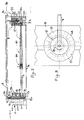
- Fig. 2 is a side view of a radial positioning system mounted on a bending table in accordance with the invention;
- Fig. 3 is an enlarged plan view of the part illustrated in Fig. 2;
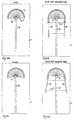
- Figs. 4A to 4D are diagrammatic plan views illustrating typical arch shaped sections to be produced;
- and Figs. 5A to 5D are similar diagrammatic views of a number of different arch shaped profiles to be produced.
-
- Referring now to the drawings, Fig. 1 illustrates a bending table 1 having a plain unslotted table top preferably of polished stainless steel upon which radial and linear arched shaped window sections may be produced. The table surface may comprise a thin plastics laminate 1a having a surface finish upon which a length of softened uPVC section may be placed without adversely affecting the under surface of the section. Beneath the thin laminate, and stainless steel, in one embodiment, is a wooden base mounted on legs to present a working surface at an operator's waist level.
- A radial positioning system as illustrated in Figs. 1 to 4 consists of a
central spindle 4 having three independently rotatinglayers spindle 4 may be positioned at any position along a slottedlocation strip 16 fixed along the centre line of the table 1. Each layer of the spindle defines a circumferential series of radially extendingapertures 13 each adapted to receive one end of a radial arm comprising an elongate hollow sleeve 6. A number of such sleeves are provided, each removably retained within its associatedaperture 13 by aspring clamp 13a. - A
rod 7 is telescopically slidable within each rod 6 and adjustably fixed by aquick release catch 20 thus to determine, within a certain range, the effective length of each radially extending sleeve androd 6, 7. Additional extension pieces may be attached to therods 7 to extend their lengths further if necessary. Eachrod 7 carries a telescopically extendible or flexibleouter sheath 21. - Mounted fixedly on the outer end of each
rod 17 is abobbin 3 presenting a bearing surface, 22 and having anelectromagnet 23 thus to be magnetically attracted to thesurface 22 of the bending table 1. An upper part 24 of each bobbin carries toggle clamps 25 for attachment thereto of aformer strip 26. A quickrelease spring clamp 27 enables apart 3a of each or some of the bobbins to be raised and lowered for adjustment with respect to the table surface, theformer strip 26 and the heated section to be formed. The bobbin alternatively may be attracted to the table by a permanent magnet. - Thus as can be seen from Fig. 2, each separately rotatable layer of the
spindle 4 may carry a plurality of radial arms and because the layers are independently rotatable it is possible either to spread thebobbins 3 evenly around a substantially semi-circular shape as illustrated or alternatively to group two or more of them closely together to produce acute bends as will become evident. - A
central core member 14 of thecentral spindle 4 has anupper flange 12 and a bottom spigot 12a which is threadedly engaged in an anchor block 12b captively located on the inverted T-sectioned slot ofstrip 16. Thus by screwing downmember 14 into anchor block 12b, the relative positions of the layers of thespindle 4 may be locked once they have been adjusted for a particular piece of work. - Permanently rotatable relative to
upper flange 12 in abearing 15, on a column 15a is aradial arm 8 which is radially extendible relative to column 15a and carries a pointer or stylus 8a. Thus by rotating thearm 8 about the axis of thespindle 4, the position of eachbobbin 3 around a semi-circular arc may be determined and set without having to measure the radial extent of each bobbin arm separately. - It will be appreciated with reference to Figs. 1 and 2, that by positioning an arcuate series of bobbins on the
table top 1 as illustrated it is then possible to extend around the bobbin the flexibleformer strip 26 around which there may be bent a length of heated and softened uPVC window or door frame section which is clamped in position to cool thus forming an arch. - If it is required to form the arched section with a pair of straight side sections thus to produce, for example, an arched window frame, there is provided on the table and adjustably mounted on
slotted strip 16, a plurality of telescopicallyextendible arms 17. Mounted at the free end of the arms is a so-calledfence 18 which may be similarly magnetically attracted to the table top and thus forms a straight edge along which a former and then a straight length of uPVC section may be positioned. Thefences 18 may extend along the remaining length of the table, where a further radial positioning system may be provided as shown at the right hand end of Fig. 1. This may extend beyond a semi circle. - A linear positioning system may incorporate an aligned series of
extendible arms 17 attached along thecentre strip 16 of the table. The strip may have two layers of receiving apertures in which thearms 17 may be located. Such arms may have bobbins attached to their free ends and so may be used in a manner similar to the radial positioning system described in relation to Figs. 1 and 2 and by using a template to position the bobbins, it is possible then to apply a former strip and a heated length of uPVC section to form a shallow arch of large and varying radius such as illustrated in Fig. 5D. - As can be seen in Fig. 1, independent, freely positionable and magnetically
attractive bobbins 30 andfences 31 may be used on the table to retain theuPVC profile strips 32. - Thus, Figs. 4A to 4D and 5D to 5D illustrate various forms of shaped section which may be produced using a bending table made in accordance with the invention. This wide variety of different shapes is easily attainable in view of the infinitely variable nature of the arms supporting the bobbins and fences. Such variation cannot be achieved on a slotted table or a table having a fixed shape of adaptor.
- Embodiments of the invention may include both radial and linear positioning systems as illustrated in Fig. 1 or one or other of such systems alone. The bobbins, fences and table surface have been described as being magnetically attractive in order to provide adequate support and prevent movement of the bobbins on the rods. This may be achieved by having the table top earthed and providing a supply of 12V +ve to electromagnets established in each bobbin and fence, or vice versa. However, the magnets may be permanent, or in some instances no magnetic attraction may be needed if there is sufficient rigidity in the structure to withstand any tendency for movement created when the former strip and section are placed around the structure. If electro-magnets are used a control or switching system may permit the user to select certain rows of the system to be magnetically active.
- The principal advantages of this system when compared with conventional bending tables is that the table surface is unslotted, flat and smooth and will not mark the heated section thus removing the need for hardboard or like templates to be cut for each curve.
- The system provides a considerable range of radii, for example, from 300mm to 1050mm. Also , any curved shape can be produced within the dimensions of the table by setting the bobbin positions as required to produce either a straight length or a curved shape with widely differing and varying curvatures. Setting up the table is a rapid and straight forward operation since no slots or clamped bobbins are required and the radial length of each arm for a curved profile is readily set by the rotating
arm 8 with stylus 8a. - Each
arm 6, 17 is easily removed from the spindle 4 (or the slotted strip 16). Thus, the arms may be interchanged at will to produce the required curvature, the arms being thus universally adjustable to produce non-uniform shapes. The arms 6 alternatively may be threadedly located inapertures 13 or by a radial screw accessible by an Allen key introduced through an aperture in the top of the spindle. - It will be appreciated that a bending table made in accordance with the invention is adaptable to produce uPVC section of any shape and configuration within the bounds of the table, a feature which cannot be achieved with any currently available conventional bending table.
Claims (18)
- A bending table comprising a table top, and a plurality of arms extending radially across the table top from a supporting member fixed with respect to the table top, at least some of said arms being adjustable in length or interchangeable, each arm having a bearing surface at its free end against which a flexible elongate work piece may be located; characterised in that the angle subtended by the or at least one pair of adjacent arms is adjustable.
- A bending table according to Claim 1, wherein the supporting member comprises at least two independently rotating spindles from which the arms radially extend.
- A bending table according to Claim 2, wherein the spindles are superimposed co-axially and each spindle defines a circumferential series of radially extending apertures each adapted to receive one end of a radial arm.
- A bending table according to any preceding claim, wherein the supporting member is adjustable in position along a location strip extending along the table.
- A bending table according to any preceding claim, in which each of said arms is telescopically adjustable in length.
- A bending table according to Claim 5, wherein each arm comprises a quick release catch to enable the effective length of the arm to be set.
- A bending table according to any preceding claim, including a bearing member located at the outer radial end of each arm thus jointly to present a bearing surface for a workpiece.
- A bending table according to Claim 7, wherein each bearing member is adjustable vertically with respect to the table top and includes a clamp for attachment to the associated bearing member of a workpiece or backing strip.
- A bending table according to Claim 2 or Claim 3, including locking means operable to fix the relative positions of the independently rotating spindles.
- A bending table according to any preceding claim, wherein the supporting member includes a further radially extending arm carrying at its outer end a marking device adapted to measure and set the radial length of each of the said plurality of arms without having to measure the radial extent of each arm separately.
- A bending table according to Claim 4, including a plurality of further telescopically extendible arms attached to said location strip and extending therefrom transversely across the table top each said further arm having a bearing surface at its free end whereby a number of such arms extending from the location strip may support a linear workpiece.
- A bending table according to Claim 11, including one or more linear fences attached to or forming the bearing surface of a number of said further telescopically extendible arms, to provide a support for a linear workpiece.
- A bending table comprising a table top, and a plurality of arms extending across the table top from a supporting member fixed with respect to the table top, at least some of said arms being adjustable in length or interchangeable, each arm having a bearing at its free end against which a flexible elongate workpiece may be located; characterised in that the bearing members and table surface are mutually magnetically attractive.
- A bending table according to Claim 13, wherein the table top is comprised of a ferro-magnetic material such as stainless steel, at least some of said plurality of arms including a magnet thus to be attracted to the table surface.
- A bending table according to claim 14, wherein the table surface is comprised of a plastics material having a surface finish upon which softened UPVC section may be placed without adversely affecting the under surface of the section.
- A bearing surface according to Claim 13, including an electro-magnet at the outer free end of each of the plurality of arms.
- A bending table according to Claim 14, wherein the ferro-magnetic table top is earthed, an electro-magnet at the outer radial end of each arm being provided with a positive electrical supply at or close to 12 volts.
- A bending table according to Claim 13, including an electrical control system permitting selected ones of said plurality of arms to be magnetically active.
Applications Claiming Priority (3)
| Application Number | Priority Date | Filing Date | Title |
|---|---|---|---|
| GB9713057 | 1997-06-21 | ||
| GBGB9713057.9A GB9713057D0 (en) | 1997-06-21 | 1997-06-21 | A bending table |
| US09/222,702 US6210140B1 (en) | 1997-06-21 | 1998-12-29 | Bending table |
Publications (3)
| Publication Number | Publication Date |
|---|---|
| EP0891856A2 EP0891856A2 (en) | 1999-01-20 |
| EP0891856A3 EP0891856A3 (en) | 2000-02-02 |
| EP0891856B1 true EP0891856B1 (en) | 2002-01-02 |
Family
ID=26311770
Family Applications (1)
| Application Number | Title | Priority Date | Filing Date |
|---|---|---|---|
| EP98304814A Expired - Lifetime EP0891856B1 (en) | 1997-06-21 | 1998-06-18 | A bending table |
Country Status (3)
| Country | Link |
|---|---|
| US (1) | US6210140B1 (en) |
| EP (1) | EP0891856B1 (en) |
| GB (2) | GB9713057D0 (en) |
Families Citing this family (4)
| Publication number | Priority date | Publication date | Assignee | Title |
|---|---|---|---|---|
| FR2799408B1 (en) * | 1999-10-06 | 2001-12-14 | Tryba | FORMING AND BENDING DEVICE, PARTICULARLY FOR PROFILES |
| US6846173B2 (en) * | 2003-01-15 | 2005-01-25 | Ching Feng Blinds Ind. Co., Ltd. | Bending machine for production of foamed decoration articles for doors and windows |
| GB0415501D0 (en) * | 2004-07-09 | 2004-08-11 | Radius Engineering Ltd | Forming means |
| CN113334743A (en) * | 2021-06-03 | 2021-09-03 | 魏元学 | Bending device for manufacturing C-shaped part in hardware of plastic-steel door and window |
Family Cites Families (8)
| Publication number | Priority date | Publication date | Assignee | Title |
|---|---|---|---|---|
| US3530540A (en) * | 1968-03-01 | 1970-09-29 | Ralph C Mueller | Molding device |
| US3776539A (en) * | 1971-05-19 | 1973-12-04 | L Miller | Plastic pipe bending jig |
| DE8313613U1 (en) * | 1983-05-07 | 1983-12-01 | Maschinen Witte Kg, 4517 Hilter | CLAMPING TABLE |
| DE3322572C2 (en) * | 1983-06-09 | 1985-04-11 | Schulten, Käthi, 4448 Emsbüren | Method and device for the arch-shaped reshaping of a profile section consisting of a thermoplastic material with hollow chambers |
| FR2569819B1 (en) * | 1984-08-31 | 1986-08-29 | Engineering Management Data Pr | TRANSFORMABLE MOLD AND MANUFACTURING METHOD THEREOF |
| ATE46479T1 (en) * | 1984-10-12 | 1989-10-15 | Isovolta | METHOD FOR HOT FORMING A RESINS PRESSED PLATE AND APPARATUS FOR CARRYING OUT THESE METHOD. |
| US4731144A (en) * | 1986-07-14 | 1988-03-15 | Harris Corporation | Method of shaping an antenna panel |
| GB2284570B (en) * | 1993-12-06 | 1997-11-05 | Alan Cunningham | Improvements in and relating to the bending of elongated plastics sections |
-
1997
- 1997-06-21 GB GBGB9713057.9A patent/GB9713057D0/en active Pending
-
1998
- 1998-06-18 EP EP98304814A patent/EP0891856B1/en not_active Expired - Lifetime
- 1998-06-18 GB GB9813078A patent/GB2326614A/en not_active Withdrawn
- 1998-12-29 US US09/222,702 patent/US6210140B1/en not_active Expired - Fee Related
Also Published As
| Publication number | Publication date |
|---|---|
| EP0891856A3 (en) | 2000-02-02 |
| EP0891856A2 (en) | 1999-01-20 |
| US6210140B1 (en) | 2001-04-03 |
| GB2326614A (en) | 1998-12-30 |
| GB9713057D0 (en) | 1997-08-27 |
| GB9813078D0 (en) | 1998-08-19 |
Similar Documents
| Publication | Publication Date | Title |
|---|---|---|
| US5590613A (en) | Apparatus for framing fabric in embroidery hoops | |
| US4939968A (en) | Glass cutting apparatus | |
| US5509367A (en) | Clamp having adjustable presser members | |
| US7144310B2 (en) | Knife sharpener apparatus | |
| JP2506538B2 (en) | Planar support device for material mounted on frame and method of use | |
| US6210140B1 (en) | Bending table | |
| US6068547A (en) | System for the profile machining with templates of slabs of marble, stone, glass and the like | |
| DE4209935A1 (en) | Universally adjustable gripper and vacuum head positioning fixture - has adjustable blocks around circumference of baseplate to enable workhead to be positioned anywhere within working envelope | |
| US7134175B2 (en) | Method for coupling a tool and tool holder using a tool assembly unit | |
| US6457428B1 (en) | Embroidery machine interchangeable frame | |
| US6845699B1 (en) | Apparatus and a method for manufacturing complex shapes | |
| US5220730A (en) | Adjustable alignment device | |
| EP0528321B1 (en) | Apparatus for mounting and welding flat articles in plate holes | |
| FI911560A0 (en) | ANORDNING FOER ATT SVETSA ETT PLASTROERSAVSNITT TILL ETT FORMSTYCKE AV PLAST. | |
| CN210649622U (en) | A quick mounting fixture for square frame work piece processing | |
| KR101904833B1 (en) | Computer-controlled sewing machine positioning system integrated with processing device, and positioning method thereof | |
| CN114952497A (en) | Glass edging positioner | |
| US4466602A (en) | Adjustable motion control apparatus for fabric spreading machines | |
| CN219293382U (en) | Automobile connecting rod processing and positioning tool | |
| US20070161331A1 (en) | Stone fabrication positioning system | |
| US4285505A (en) | Apparatus for use in forming a finish on a jewelry band | |
| CN218561817U (en) | Accessory sewing auxiliary frame | |
| KR200381999Y1 (en) | Apparatus for adjusting the height of a desk | |
| CN218710323U (en) | Culture dish placer | |
| CN224185523U (en) | Wide-width positioning tool adapting to multi-specification flame-retardant polyester viscose cloth |
Legal Events
| Date | Code | Title | Description |
|---|---|---|---|
| PUAI | Public reference made under article 153(3) epc to a published international application that has entered the european phase |
Free format text: ORIGINAL CODE: 0009012 |
|
| AK | Designated contracting states |
Kind code of ref document: A2 Designated state(s): AT BE CH CY DE DK ES FI FR GB GR IE IT LI LU MC NL PT SE |
|
| AX | Request for extension of the european patent |
Free format text: AL;LT;LV;MK;RO;SI |
|
| PUAL | Search report despatched |
Free format text: ORIGINAL CODE: 0009013 |
|
| AK | Designated contracting states |
Kind code of ref document: A3 Designated state(s): AT BE CH CY DE DK ES FI FR GB GR IE IT LI LU MC NL PT SE |
|
| AX | Request for extension of the european patent |
Free format text: AL;LT;LV;MK;RO;SI |
|
| 17P | Request for examination filed |
Effective date: 20000726 |
|
| AKX | Designation fees paid |
Free format text: AT BE CH CY DE DK ES FI FR GB GR IE IT LI LU MC NL PT SE |
|
| GRAG | Despatch of communication of intention to grant |
Free format text: ORIGINAL CODE: EPIDOS AGRA |
|
| 17Q | First examination report despatched |
Effective date: 20010904 |
|
| GRAG | Despatch of communication of intention to grant |
Free format text: ORIGINAL CODE: EPIDOS AGRA |
|
| GRAH | Despatch of communication of intention to grant a patent |
Free format text: ORIGINAL CODE: EPIDOS IGRA |
|
| GRAH | Despatch of communication of intention to grant a patent |
Free format text: ORIGINAL CODE: EPIDOS IGRA |
|
| GRAA | (expected) grant |
Free format text: ORIGINAL CODE: 0009210 |
|
| REG | Reference to a national code |
Ref country code: GB Ref legal event code: IF02 |
|
| AK | Designated contracting states |
Kind code of ref document: B1 Designated state(s): AT BE CH CY DE DK ES FI FR GB GR IE IT LI LU MC NL PT SE |
|
| PG25 | Lapsed in a contracting state [announced via postgrant information from national office to epo] |
Ref country code: NL Free format text: LAPSE BECAUSE OF FAILURE TO SUBMIT A TRANSLATION OF THE DESCRIPTION OR TO PAY THE FEE WITHIN THE PRESCRIBED TIME-LIMIT Effective date: 20020102 Ref country code: LI Free format text: LAPSE BECAUSE OF FAILURE TO SUBMIT A TRANSLATION OF THE DESCRIPTION OR TO PAY THE FEE WITHIN THE PRESCRIBED TIME-LIMIT Effective date: 20020102 Ref country code: GR Free format text: LAPSE BECAUSE OF FAILURE TO SUBMIT A TRANSLATION OF THE DESCRIPTION OR TO PAY THE FEE WITHIN THE PRESCRIBED TIME-LIMIT Effective date: 20020102 Ref country code: FR Free format text: LAPSE BECAUSE OF FAILURE TO SUBMIT A TRANSLATION OF THE DESCRIPTION OR TO PAY THE FEE WITHIN THE PRESCRIBED TIME-LIMIT Effective date: 20020102 Ref country code: FI Free format text: LAPSE BECAUSE OF FAILURE TO SUBMIT A TRANSLATION OF THE DESCRIPTION OR TO PAY THE FEE WITHIN THE PRESCRIBED TIME-LIMIT Effective date: 20020102 Ref country code: CH Free format text: LAPSE BECAUSE OF FAILURE TO SUBMIT A TRANSLATION OF THE DESCRIPTION OR TO PAY THE FEE WITHIN THE PRESCRIBED TIME-LIMIT Effective date: 20020102 Ref country code: BE Free format text: LAPSE BECAUSE OF FAILURE TO SUBMIT A TRANSLATION OF THE DESCRIPTION OR TO PAY THE FEE WITHIN THE PRESCRIBED TIME-LIMIT Effective date: 20020102 |
|
| REF | Corresponds to: |
Ref document number: 211435 Country of ref document: AT Date of ref document: 20020115 Kind code of ref document: T |
|
| REG | Reference to a national code |
Ref country code: CH Ref legal event code: EP |
|
| REG | Reference to a national code |
Ref country code: IE Ref legal event code: FG4D |
|
| REF | Corresponds to: |
Ref document number: 69803339 Country of ref document: DE Date of ref document: 20020228 |
|
| PG25 | Lapsed in a contracting state [announced via postgrant information from national office to epo] |
Ref country code: SE Free format text: LAPSE BECAUSE OF FAILURE TO SUBMIT A TRANSLATION OF THE DESCRIPTION OR TO PAY THE FEE WITHIN THE PRESCRIBED TIME-LIMIT Effective date: 20020402 Ref country code: DK Free format text: LAPSE BECAUSE OF FAILURE TO SUBMIT A TRANSLATION OF THE DESCRIPTION OR TO PAY THE FEE WITHIN THE PRESCRIBED TIME-LIMIT Effective date: 20020402 |
|
| NLV1 | Nl: lapsed or annulled due to failure to fulfill the requirements of art. 29p and 29m of the patents act | ||
| PG25 | Lapsed in a contracting state [announced via postgrant information from national office to epo] |
Ref country code: MC Free format text: LAPSE BECAUSE OF NON-PAYMENT OF DUE FEES Effective date: 20020618 Ref country code: LU Free format text: LAPSE BECAUSE OF NON-PAYMENT OF DUE FEES Effective date: 20020618 |
|
| REG | Reference to a national code |
Ref country code: PT Ref legal event code: SC4A Free format text: AVAILABILITY OF NATIONAL TRANSLATION Effective date: 20020326 |
|
| PG25 | Lapsed in a contracting state [announced via postgrant information from national office to epo] |
Ref country code: CY Free format text: LAPSE BECAUSE OF FAILURE TO SUBMIT A TRANSLATION OF THE DESCRIPTION OR TO PAY THE FEE WITHIN THE PRESCRIBED TIME-LIMIT Effective date: 20020630 |
|
| REG | Reference to a national code |
Ref country code: CH Ref legal event code: PL |
|
| PG25 | Lapsed in a contracting state [announced via postgrant information from national office to epo] |
Ref country code: ES Free format text: LAPSE BECAUSE OF FAILURE TO SUBMIT A TRANSLATION OF THE DESCRIPTION OR TO PAY THE FEE WITHIN THE PRESCRIBED TIME-LIMIT Effective date: 20020730 |
|
| EN | Fr: translation not filed | ||
| PLBE | No opposition filed within time limit |
Free format text: ORIGINAL CODE: 0009261 |
|
| STAA | Information on the status of an ep patent application or granted ep patent |
Free format text: STATUS: NO OPPOSITION FILED WITHIN TIME LIMIT |
|
| 26N | No opposition filed | ||
| NLV1 | Nl: lapsed or annulled due to failure to fulfill the requirements of art. 29p and 29m of the patents act | ||
| PGFP | Annual fee paid to national office [announced via postgrant information from national office to epo] |
Ref country code: AT Payment date: 20080515 Year of fee payment: 11 |
|
| PGFP | Annual fee paid to national office [announced via postgrant information from national office to epo] |
Ref country code: PT Payment date: 20080519 Year of fee payment: 11 Ref country code: IT Payment date: 20080529 Year of fee payment: 11 |
|
| PGFP | Annual fee paid to national office [announced via postgrant information from national office to epo] |
Ref country code: IE Payment date: 20080522 Year of fee payment: 11 Ref country code: DE Payment date: 20080523 Year of fee payment: 11 |
|
| PGFP | Annual fee paid to national office [announced via postgrant information from national office to epo] |
Ref country code: GB Payment date: 20080411 Year of fee payment: 11 |
|
| REG | Reference to a national code |
Ref country code: PT Ref legal event code: MM4A Free format text: LAPSE DUE TO NON-PAYMENT OF FEES Effective date: 20091218 |
|
| GBPC | Gb: european patent ceased through non-payment of renewal fee |
Effective date: 20090618 |
|
| PG25 | Lapsed in a contracting state [announced via postgrant information from national office to epo] |
Ref country code: PT Free format text: LAPSE BECAUSE OF NON-PAYMENT OF DUE FEES Effective date: 20091218 |
|
| REG | Reference to a national code |
Ref country code: IE Ref legal event code: MM4A |
|
| PG25 | Lapsed in a contracting state [announced via postgrant information from national office to epo] |
Ref country code: IE Free format text: LAPSE BECAUSE OF NON-PAYMENT OF DUE FEES Effective date: 20090618 |
|
| PG25 | Lapsed in a contracting state [announced via postgrant information from national office to epo] |
Ref country code: GB Free format text: LAPSE BECAUSE OF NON-PAYMENT OF DUE FEES Effective date: 20090618 |
|
| PG25 | Lapsed in a contracting state [announced via postgrant information from national office to epo] |
Ref country code: DE Free format text: LAPSE BECAUSE OF NON-PAYMENT OF DUE FEES Effective date: 20100101 Ref country code: AT Free format text: LAPSE BECAUSE OF NON-PAYMENT OF DUE FEES Effective date: 20090618 |
|
| PG25 | Lapsed in a contracting state [announced via postgrant information from national office to epo] |
Ref country code: IT Free format text: LAPSE BECAUSE OF NON-PAYMENT OF DUE FEES Effective date: 20090618 |