EP0891584B1 - Collection of events within a distributed object system - Google Patents
Collection of events within a distributed object system Download PDFInfo
- Publication number
- EP0891584B1 EP0891584B1 EP97914434A EP97914434A EP0891584B1 EP 0891584 B1 EP0891584 B1 EP 0891584B1 EP 97914434 A EP97914434 A EP 97914434A EP 97914434 A EP97914434 A EP 97914434A EP 0891584 B1 EP0891584 B1 EP 0891584B1
- Authority
- EP
- European Patent Office
- Prior art keywords
- client
- event
- filter
- objects
- server
- Prior art date
- Legal status (The legal status is an assumption and is not a legal conclusion. Google has not performed a legal analysis and makes no representation as to the accuracy of the status listed.)
- Expired - Lifetime
Links
Images


Classifications
-
- G—PHYSICS
- G06—COMPUTING; CALCULATING OR COUNTING
- G06F—ELECTRIC DIGITAL DATA PROCESSING
- G06F9/00—Arrangements for program control, e.g. control units
- G06F9/06—Arrangements for program control, e.g. control units using stored programs, i.e. using an internal store of processing equipment to receive or retain programs
- G06F9/46—Multiprogramming arrangements
- G06F9/54—Interprogram communication
- G06F9/542—Event management; Broadcasting; Multicasting; Notifications
-
- G—PHYSICS
- G06—COMPUTING; CALCULATING OR COUNTING
- G06F—ELECTRIC DIGITAL DATA PROCESSING
- G06F9/00—Arrangements for program control, e.g. control units
- G06F9/06—Arrangements for program control, e.g. control units using stored programs, i.e. using an internal store of processing equipment to receive or retain programs
- G06F9/46—Multiprogramming arrangements
- G06F9/465—Distributed object oriented systems
Definitions
- the present invention relates to the collection of events within a Distributed Object System.
- Distributed Computing is an area of computing in which distinct software modules running on physically separate computing nodes can communicate with each other, and can request each other to perform tasks.
- object-oriented technology has given Distributed Computing extra impetus in recent years, and the convergence of the two technologies has resulted in Distributed Object Technology.
- the invention also extends to a corresponding method, and in particular extends, in a second aspect of the invention, to a method of characterising a Distributed Object System having a plurality of objects, the method comprising providing each object with an associated filter which is arranged to intercept messages sent or received by its corresponding object and to forward information representative of said messages to an Event Collector, the Distributed Object System being characterised according to the messages received by the Event Collector.
- the messages collected by the Event Collector may be representative of a predefined class of events, for example the class of interactions between objects and the deletion and creation of objects.
- the Event Collector may forward collected events to an Event Dispatch Mechanism, which processes the events and forwards them to one or more User Applications.
- These User Applications may take a variety of different forms. including Visualizer Applications. Fault Detecting Applications. Control Applications and Charging Applications.
- several different User Applications (objects) may be running simultaneously. and each may be independently configurable. Depending upon the particular requirements, the configuration may be automatic or user-defined.
- system may provide fault reporting and/or fault recovery services within a Distributed Object System.
- the system accordingly provides a tool or series of tools which can collect information, in a well defined way, from the various objects within a Distributed Object System.
- the information thus collected may then be used to analyse the system, for example to find out what has happened during a system failure or other unexpected event.
- the information collected may be used to assist system designers who are attempting to explain the system to other people who are not directly involved in development.
- Distributed Object Systems are extremely difficult to explain, and the present invention in at least some forms, will improve the "information transfer" process from developers and designers to technical collaborators and customers.
- CORBA Common Object Request Broker Architecture
- OMG Object Management Group
- RPC Remote Procedure Call
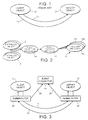
- a client object 10 sends a message 11 to a remote server object, requesting a particular operation.
- the server object 12 executes the code which corresponds to this operation, and then returns control to the client 10 by means of a reply message 13.
- the outgoing message 11 contains the name of the operation to be invoked along with the arguments to the operation, while the reply message contains the name of the operation that was invoked along with the results of the operation.
- an alternative interaction style used in CORBA is the "one-way" style.
- the message to invoke an operation is sent to the server object, but in the meantime the client object continues to execute its own code.
- the server object completes the execution of the operation concerned, no message is sent back.
- This may be viewed simply as a conventional RPC in which there are no results, and in which no confirmation is sent back from the server object to the client object.
- the third and final subsystem comprises an Event Dispatch Mechanism 16; this takes the stream of events from the collection mechanism 14 and dispatches it to each of the individual Visualizer Applications 18a, 18b, 18c. It will be understood, of course, that the Event Collection Mechanism 14, the Event Dispatch Mechanism 16 and the Visualizer Applications 18 may all be considered as objects in their own right.
- Figure 3 shows in more detail the interactions between the individual objects and the Event Collection Mechanism 14.
- the reference numerals used for those elements corresponding to the RPC model correspond to the numerals used in Figure 1.
- the event collector 14 collects events 26,28 which are transmitted by filters 20,22 associated respectively with the client object 10 and the server object 12.
- the filters themselves may comprise the filters present in the CORBA conformant product Orbix.
- Orbix is a commercial software product available from Iona Technologies. This allows software to be inserted which will be run during the arrival, dispatch, reply and return of messages (object interactions).
- the event collector 14 collects information relating to the transmission of a message from one object to another (that is the invocation of an operation on one object by another). or the creation or deletion of an object.
- the filters are associated with the objects in such a way that they intercept messages being sent and received, but without requiring any changes to the objects themselves.
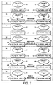
- Figure 6a illustrates the situation prior to Object A invoking a request on Object B.
- the filter 20 associated with Object A contains a unique Key A
- the filter 22 associated with the Object B contains a unique Key B.
- Figure 6b shows the situation as Object A invokes a request on Object B.
- An outgoing message 11 is passed between Object A and Object B, this message being intercepted as previously described by the filter 20 which generates a reporting message 30.
- the filter 20 attaches to the message 11 its own key, Key A, and that is passed on to the receiving filter 22, which currently contains Key B.
- the filter 22 takes on Key A in replacement for its original key, and passes the rest of the message on to Object B.
- Figure 6c shows the situation while the request is being serviced by Object B.
- Object B's filter 22 has now taken on Key A.
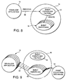
- Figure 7a shows the situation before Object A invokes a request on Object B.
- Figure 7g shows what happens when Object B completes its request, and returns control back to Object A.
- the reply message is sent back from Object B to Object A, and Object B's filter 22 takes on again its original key, Key B.
- Object A's filter 20 sends out yet another message 50 to the Event Collection Mechanism. Once again, this message will contain the Key A, since that is the key currently associated with the filter 20.
- the key is propagated from one object to the next, by adding it to the message at the sending filter, and removing it from the message at the receiving filter.
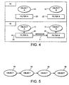
- Event Dispatch Mechanism 16 receives details of all events collected by the Event Collection Mechanism 14, and is arranged to forward those particular events that the user is interested in to the Visualizer Application 18.
- Event Dispatch Mechanism 16 incorporates within it an object, known as the Event Dispatcher Factory 52. responsible for creating further objects 54 known as Event Dispatchers. Each Event Dispatcher is responsible for sending events to a particular Visualizer Application. A user who wishes to view a particular subset of events runs the Visualizer Application Object 18, which then registers as indicated by numeral 56 with the Event Dispatch Mechanism 16.
- Event Dispatcher Factory 52 creates a new Event Dispatcher Object 54 which passes information as indicated at 58 to its corresponding Visualizer Application.
- Each Visualizer Application 18 may be configured differently, and may require information on a different subset of the events which have been collected (or are being collected) by the Event Collection Mechanism 14. The necessary filtering is carried out by the respective Event Dispatcher 54 which passes on only that information which has been requested by its individual Visualizer Application.
- the Visualizer Application 18 may take many forms, having a variety of front-ends, the preferred version being illustrated schematically in Figure 10.
- the user of the Visualizer Application sees information displayed graphically within a large window 60. Within a workspace 62 of the window are displayed the various objects that the Visualizer Application has been configured to show. Typically, the display will show a plurality of object icons 64, connected by arrows 66. Each icon 64 represents a particular object, with the arrows representing interactions between the objects. Certain of the arrows 67 and/or the object icons 68 may be displayed in a different colour to indicate the active (current) interaction and/or object. In the preferred display, the most recently displayed interaction is shown in red; as another event arrives, that becomes the active interaction and the previous active interaction becomes grey.
- the window 60 may further include a tool bar 70 having a status display 72 and a plurality of buttons 74 whereby the user may configure the display to his or her requirements.
- the Visualizer Application can be configured by loading in a configuration file which contains information about:
- the Visualizer Application 18 may be replaced by other objects that can make use of the information collected by the Event Collection Mechanism.
- a Fault-Reporting Application could provide for fault-monitoring of a Distributed Object System.
- Such an application might include the production of system alarms where unexpected events have occurred, along with error-recovery objects designed to modify the operation of the system in the event of an alarm.
- the system could, for instance, be closed down entirely automatically in appropriate circumstances, or other fault-recovery objects could be run.
- the system of the present invention may therefore be useful not only to system designers and maintainers, but also as a means of monitoring an Operational Distributed Object System.
- the Visualizer Application may be replaced with a Charging Application.
- the events collected by the Event Collection Mechanism may then be used to charge for the use of objects or services.
- the DPE is an infrastructure (of a type known per se) that supports the interactions of the various objects previously discussed.
- the purpose of the DPE is, amongst other things, to shield the application programs from the heterogeneous and distributed nature of the underlying environment, and to provide a mechanism that allows objects to interact without a knowledge of the details of the particular computing node they are active on.
- the DPE defines four types of entity: a DPE kernel 811, a kernel transport network 901, DPE stubs, and DPE servers 809.
- the kernel transport network 901 is linked as shown in the Figure with a plurality of interlinked computing nodes 810.
- the DPE kernel defines a core set of communications, storage and processing capabilities (for example a protocol stack) which is assumed to be present on each node.
- the kernel transport network 901 is a communications network to which all DPE kernels are attached in order to exchange messages to facilitate object interaction. It is defined in order logically to separate the computing network from a transport network which may be used for the transmission of voice and video. The logical separation recognises that the two networks may have different requirements on quality of service.
- the DPE servers 809 provide infrastructure support, for example in the form of a trader and a notification server.
- a trader provides a run-time mechanism that allows objects to locate the interfaces of other objects.
- a notification server enables objects to emit notifications (for example significant events that occur during the lifetime of an object) to other objects. Objects wishing to receive notifications register at run-time with the notification server.
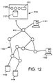
- FIG. 12 there is shown a hardware view of a system on which embodiments of the present invention might operate.
- the hardware is based around a transport network 1100 which will carry the data services provided by service providers to individual users of the system.
- the data transmitted across the network 1100 might include, for example, voice and/or video information.
- Individual users are connected to the network by different pieces of customer premises equipment (CPE) 1101, 1102.
- CPE customer premises equipment
- the various parties involved in offering and carrying the network services such as service retailers, service providers and network providers, are connected to the transport network at a computational node 810.
- Each computational node 810 includes a variety of hardware and software features, indicated generally at 812. These include a DPE kernel 811, a protocol stack for use according to DPE principles, storage facilities 1121 and applications 1120 running at the computational node.
- the system will also include a variety of data stores 1105, 1106 coupled to the transport network, as shown.
- One of these data stores 1105 may comprise a management information data store, to provide global management information in respect of services provided by the network.
- an instance of the visualiser application 18 may be run at any of the individual computational nodes 810.
- the application will collect information from distributed objects across the network, and may report by way of the information screen shown in Figure 10 at the individual operator's own terminal.
Description
- Type 1 object -
- This type of object is always visible on the screen of the Visualizer Application.
-
Type 2 object - - This type of object becomes visible when an event is received that tells the Visualizer Application that the object has been created. and becomes hidden when an event arrives that corresponds to the deletion of the object.
- Type 3 object -
- This type of object becomes visible when an interaction is displayed that goes to the object, but is hidden by the arrival of a deletion event.
Claims (18)
- A system for visualizing objects within a distributed object system, the system having a plurality of objects (10, 12), each object having an associated filter (20, 22) arranged to intercept messages (11, 13) sent or received by its corresponding object and to forward information representative of said messages to an event collector (14); and a visualizer application (18) arranged to receive the said information and having a graphical front-end (60) for displaying to a user a graphical representation of the distributed object system, the visualizer application being user-configurable to display a selected category of objects within the system.
- A system as claimed in Claim 1 in which the filter is further arranged to forward information to the event collector on the creation or deletion of a corresponding object.
- A system as claimed in Claim 1 or Claim 2 in which each client object has an associated client filter, the client filter having a client key which is representative of the client object.
- A system as claimed in Claim 3 in which when the client object sends an outgoing message to a server object invoking the server object, the client filter forwards information representative of the client key to the event collector.
- A system as claimed in Claim 3 in which when the client object sends an outgoing message to a server object invoking the server object, the client filter adds to the outgoing message information representative of the client key.
- A system as claimed in Claim 5 in which the outgoing message is received by a server filter associated with the server object, the server filter being arranged to replace the server key with the client key on receipt of the outgoing message.
- A system as claimed in Claim 6 in which when the server object sends a reply message to the client object returning control to the client object, the server filter replaces the client key with the server key.
- A system as claimed in Claim 7 in which the reply message is received by the client filter, the client filter being arranged to forward further information representative of the client key to the event collector.
- A system as claimed in any one of the preceding claims in which the plurality of objects are themselves arranged to interact as the distributed object system, independently of the filters; the filters being associated with, but not altering any code of, the objects.
- A system as claimed in Claim 1 in which the information forwarded to the event collector includes information identifying a base object, the base object being the first instigator of an outgoing server-invoking message which has ultimately resulted in the said intercepted message.
- A system as claimed in Claim 1 in which the filter is CORBA-compliant.
- A system as claimed in any one of the preceding claims in which events collected by the event collector are processed by an event dispatch mechanism (16) and are forwarded to the visualizer application.
- A distributed object system as claimed in Claim 12 in which the event dispatch mechanism is arranged to forward to the visualizer application only events of interest to the user.
- A distributed object system as claimed in Claim 12 or Claim 13 in which the event collector is arranged to forward processed events to a plurality of visualizer applications.
- A distributed object system as claimed in Claim 14 in which the separate visualizer applications are concurrently-running objects.
- A distributed object system as claimed in any one of Claims 12 to 15 in which the or each visualizer application is arranged to register with the event dispatch mechanism.
- A distributed object system as claimed in Claim 16 in which an event dispatcher factory (52) of the event dispatcher mechanism is arranged to create an event dispatcher (54) for each registration of the visualizer application with the event dispatcher mechanism, the event dispatcher being arranged to forward events to its respective visualizer application based on a configuration of the said respective visualizer application.
- A method of visualizing a distributed object system having a plurality of objects (10, 12), the method comprising providing each object with an associated filter (20, 22) which is arranged to intercept messages (11, 13) sent or received by its corresponding object and to forward information representative of said messages to an event collector (14), the distributed object system being visualized graphically by a user-configurable visualizer application (18) arranged to display a user-selected category of objects within the system, based on said information received from the event collector.
Applications Claiming Priority (3)
| Application Number | Priority Date | Filing Date | Title |
|---|---|---|---|
| GB9606733 | 1996-03-29 | ||
| GBGB9606733.5A GB9606733D0 (en) | 1996-03-29 | 1996-03-29 | Collection of events within a distributed object system |
| PCT/GB1997/000834 WO1997037304A1 (en) | 1996-03-29 | 1997-03-25 | Collection of events within a distributed object system |
Publications (2)
| Publication Number | Publication Date |
|---|---|
| EP0891584A1 EP0891584A1 (en) | 1999-01-20 |
| EP0891584B1 true EP0891584B1 (en) | 2001-07-04 |
Family
ID=10791327
Family Applications (1)
| Application Number | Title | Priority Date | Filing Date |
|---|---|---|---|
| EP97914434A Expired - Lifetime EP0891584B1 (en) | 1996-03-29 | 1997-03-25 | Collection of events within a distributed object system |
Country Status (9)
| Country | Link |
|---|---|
| US (1) | US6658487B1 (en) |
| EP (1) | EP0891584B1 (en) |
| JP (1) | JP2000507724A (en) |
| CN (1) | CN1220018A (en) |
| AU (1) | AU712616B2 (en) |
| CA (1) | CA2248096C (en) |
| DE (1) | DE69705507D1 (en) |
| GB (1) | GB9606733D0 (en) |
| WO (1) | WO1997037304A1 (en) |
Families Citing this family (28)
| Publication number | Priority date | Publication date | Assignee | Title |
|---|---|---|---|---|
| US6684246B1 (en) * | 1999-02-03 | 2004-01-27 | William H. Gates, III | Method and system for tracking clients |
| US6782541B1 (en) * | 1999-05-28 | 2004-08-24 | Avaya Technology Corp. | System and method of exchanging information between software modules |
| AU2001262970A1 (en) * | 2000-05-02 | 2001-11-12 | Sun Microsystems, Inc. | Event service method and system |
| US20030081003A1 (en) * | 2001-02-23 | 2003-05-01 | Ali Kutay | System and method to facilitate analysis and removal of errors from an application |
| US20020124029A1 (en) * | 2001-03-02 | 2002-09-05 | Gwinn John Glen | Method and apparatus for creating, embedding and using a searchable font |
| DE10118502C1 (en) | 2001-04-12 | 2002-08-08 | Siemens Ag | Process for the acquisition and recording of system information and processes in distributed concurrent component-based software systems |
| US8291434B1 (en) * | 2001-06-13 | 2012-10-16 | Digi International Inc. | Computer system and method to dispatch and receive a message responsive to the occurrence of an event |
| US7831655B2 (en) * | 2001-10-18 | 2010-11-09 | Bea Systems, Inc. | System and method for implementing a service adapter |
| US6931405B2 (en) * | 2002-04-15 | 2005-08-16 | Microsoft Corporation | Flexible subscription-based event notification |
| US7937344B2 (en) | 2005-07-25 | 2011-05-03 | Splunk Inc. | Machine data web |
| JP2007048023A (en) * | 2005-08-10 | 2007-02-22 | Hitachi Software Eng Co Ltd | Composite interface indicator light and notification system using indicator light |
| CN102831214B (en) | 2006-10-05 | 2017-05-10 | 斯普兰克公司 | time series search engine |
| US8015571B2 (en) * | 2007-03-16 | 2011-09-06 | Google Inc. | Registering an event |
| US11182175B2 (en) * | 2008-09-18 | 2021-11-23 | International Business Machines Corporation | Apparatus and methods for workflow capture and display |
| US8786702B2 (en) * | 2009-08-31 | 2014-07-22 | Behavioral Recognition Systems, Inc. | Visualizing and updating long-term memory percepts in a video surveillance system |
| CN102387169B (en) | 2010-08-26 | 2014-07-23 | 阿里巴巴集团控股有限公司 | Delete method, system and delete server for distributed cache objects |
| US20130091266A1 (en) * | 2011-10-05 | 2013-04-11 | Ajit Bhave | System for organizing and fast searching of massive amounts of data |
| US10318541B2 (en) | 2013-04-30 | 2019-06-11 | Splunk Inc. | Correlating log data with performance measurements having a specified relationship to a threshold value |
| US10019496B2 (en) | 2013-04-30 | 2018-07-10 | Splunk Inc. | Processing of performance data and log data from an information technology environment by using diverse data stores |
| US10225136B2 (en) | 2013-04-30 | 2019-03-05 | Splunk Inc. | Processing of log data and performance data obtained via an application programming interface (API) |
| US10614132B2 (en) | 2013-04-30 | 2020-04-07 | Splunk Inc. | GUI-triggered processing of performance data and log data from an information technology environment |
| US10346357B2 (en) | 2013-04-30 | 2019-07-09 | Splunk Inc. | Processing of performance data and structure data from an information technology environment |
| US10353957B2 (en) | 2013-04-30 | 2019-07-16 | Splunk Inc. | Processing of performance data and raw log data from an information technology environment |
| US10997191B2 (en) | 2013-04-30 | 2021-05-04 | Splunk Inc. | Query-triggered processing of performance data and log data from an information technology environment |
| US9363149B1 (en) | 2015-08-01 | 2016-06-07 | Splunk Inc. | Management console for network security investigations |
| US10254934B2 (en) | 2015-08-01 | 2019-04-09 | Splunk Inc. | Network security investigation workflow logging |
| US9516052B1 (en) | 2015-08-01 | 2016-12-06 | Splunk Inc. | Timeline displays of network security investigation events |
| US10440054B2 (en) * | 2015-09-25 | 2019-10-08 | Perspecta Labs Inc. | Customized information networks for deception and attack mitigation |
Family Cites Families (6)
| Publication number | Priority date | Publication date | Assignee | Title |
|---|---|---|---|---|
| CN1059981A (en) * | 1988-12-30 | 1992-04-01 | 惠普公司 | Manage the encapsulation of the application program of facility environment for holding into a pair of orthicon |
| US5822527A (en) * | 1990-05-04 | 1998-10-13 | Digital Equipment Corporation | Method and apparatus for information stream filtration using tagged information access and action registration |
| DE69029515D1 (en) * | 1990-06-28 | 1997-02-06 | Ibm | Message processing in a data processing device |
| CA2118169A1 (en) * | 1993-10-27 | 1995-04-28 | Michael R.C. Seaman | Event architecture for system management in an operating system |
| US5734903A (en) * | 1994-05-13 | 1998-03-31 | Apple Computer, Inc. | System and method for object oriented message filtering |
| US5774669A (en) * | 1995-07-28 | 1998-06-30 | The United States Of America As Represented By The Administrator Of The National Aeronautics And Space Administration | Scalable hierarchical network management system for displaying network information in three dimensions |
-
1996
- 1996-03-29 GB GBGB9606733.5A patent/GB9606733D0/en active Pending
-
1997
- 1997-03-25 JP JP9535014A patent/JP2000507724A/en not_active Ceased
- 1997-03-25 AU AU21681/97A patent/AU712616B2/en not_active Ceased
- 1997-03-25 US US09/043,147 patent/US6658487B1/en not_active Expired - Lifetime
- 1997-03-25 CN CN97195059A patent/CN1220018A/en active Pending
- 1997-03-25 DE DE69705507T patent/DE69705507D1/en not_active Expired - Lifetime
- 1997-03-25 WO PCT/GB1997/000834 patent/WO1997037304A1/en active IP Right Grant
- 1997-03-25 EP EP97914434A patent/EP0891584B1/en not_active Expired - Lifetime
- 1997-03-25 CA CA002248096A patent/CA2248096C/en not_active Expired - Fee Related
Also Published As
| Publication number | Publication date |
|---|---|
| DE69705507D1 (en) | 2001-08-09 |
| CN1220018A (en) | 1999-06-16 |
| CA2248096C (en) | 2003-02-18 |
| GB9606733D0 (en) | 1996-06-05 |
| CA2248096A1 (en) | 1997-10-09 |
| EP0891584A1 (en) | 1999-01-20 |
| AU712616B2 (en) | 1999-11-11 |
| JP2000507724A (en) | 2000-06-20 |
| US6658487B1 (en) | 2003-12-02 |
| AU2168197A (en) | 1997-10-22 |
| WO1997037304A1 (en) | 1997-10-09 |
Similar Documents
| Publication | Publication Date | Title |
|---|---|---|
| EP0891584B1 (en) | Collection of events within a distributed object system | |
| US6255943B1 (en) | Method and apparatus for distributed object filtering | |
| US6373383B1 (en) | Method and apparatus for policy-based alarm notification in a distributed network management environment | |
| US6356282B2 (en) | Alarm manager system for distributed network management system | |
| EP0651328B1 (en) | Event architecture for system management in an operating system | |
| US6526442B1 (en) | Programmable operational system for managing devices participating in a network | |
| US5696486A (en) | Method and apparatus for policy-based alarm notification in a distributed network management environment | |
| EP0549677B1 (en) | Network management system using model-based intelligence | |
| US7221377B1 (en) | Apparatus and method for collecting and displaying information in a workflow system | |
| US5261044A (en) | Network management system using multifunction icons for information display | |
| EP1166217B1 (en) | Distributed software system visualisation | |
| US6754704B1 (en) | Methods, systems, and computer program product for remote monitoring of a data processing system events | |
| US7739325B1 (en) | Apparatus and method for extensible real-time workflows | |
| EP1143361A1 (en) | A knowledge system and methods of business alerting or analysis | |
| US20040128698A1 (en) | Apparatus and methods for scheduling events | |
| JP2000181756A (en) | Method and device for state display | |
| Brunner et al. | Management of Active Networks | |
| AU720061C (en) | Method and apparatus for policy-based alarm notification in a distributed network management environment | |
| US6978442B2 (en) | Auditing data using observable and observer objects | |
| Hanmer et al. | An input and output pattern language: Lessions from telecommunications | |
| US20060002374A1 (en) | System and method for event notification in a J2EE environment | |
| Karhinen et al. | An architectural style decoupling coordination, computation and data | |
| Richardson et al. | SMT: A System Monitoring Tool for DCE |
Legal Events
| Date | Code | Title | Description |
|---|---|---|---|
| PUAI | Public reference made under article 153(3) epc to a published international application that has entered the european phase |
Free format text: ORIGINAL CODE: 0009012 |
|
| 17P | Request for examination filed |
Effective date: 19980904 |
|
| AK | Designated contracting states |
Kind code of ref document: A1 Designated state(s): CH DE FI FR GB IE IT LI NL SE |
|
| 17Q | First examination report despatched |
Effective date: 19990514 |
|
| GRAG | Despatch of communication of intention to grant |
Free format text: ORIGINAL CODE: EPIDOS AGRA |
|
| GRAG | Despatch of communication of intention to grant |
Free format text: ORIGINAL CODE: EPIDOS AGRA |
|
| GRAH | Despatch of communication of intention to grant a patent |
Free format text: ORIGINAL CODE: EPIDOS IGRA |
|
| GRAH | Despatch of communication of intention to grant a patent |
Free format text: ORIGINAL CODE: EPIDOS IGRA |
|
| GRAA | (expected) grant |
Free format text: ORIGINAL CODE: 0009210 |
|
| AK | Designated contracting states |
Kind code of ref document: B1 Designated state(s): CH DE FI FR GB IE IT LI NL SE |
|
| PG25 | Lapsed in a contracting state [announced via postgrant information from national office to epo] |
Ref country code: NL Free format text: LAPSE BECAUSE OF FAILURE TO SUBMIT A TRANSLATION OF THE DESCRIPTION OR TO PAY THE FEE WITHIN THE PRESCRIBED TIME-LIMIT Effective date: 20010704 Ref country code: LI Free format text: LAPSE BECAUSE OF FAILURE TO SUBMIT A TRANSLATION OF THE DESCRIPTION OR TO PAY THE FEE WITHIN THE PRESCRIBED TIME-LIMIT Effective date: 20010704 Ref country code: IT Free format text: LAPSE BECAUSE OF FAILURE TO SUBMIT A TRANSLATION OF THE DESCRIPTION OR TO PAY THE FEE WITHIN THE PRESCRIBED TIME-LIMIT;WARNING: LAPSES OF ITALIAN PATENTS WITH EFFECTIVE DATE BEFORE 2007 MAY HAVE OCCURRED AT ANY TIME BEFORE 2007. THE CORRECT EFFECTIVE DATE MAY BE DIFFERENT FROM THE ONE RECORDED. Effective date: 20010704 Ref country code: FI Free format text: LAPSE BECAUSE OF FAILURE TO SUBMIT A TRANSLATION OF THE DESCRIPTION OR TO PAY THE FEE WITHIN THE PRESCRIBED TIME-LIMIT Effective date: 20010704 Ref country code: CH Free format text: LAPSE BECAUSE OF FAILURE TO SUBMIT A TRANSLATION OF THE DESCRIPTION OR TO PAY THE FEE WITHIN THE PRESCRIBED TIME-LIMIT Effective date: 20010704 |
|
| REG | Reference to a national code |
Ref country code: CH Ref legal event code: EP |
|
| REG | Reference to a national code |
Ref country code: IE Ref legal event code: FG4D |
|
| REF | Corresponds to: |
Ref document number: 69705507 Country of ref document: DE Date of ref document: 20010809 |
|
| PG25 | Lapsed in a contracting state [announced via postgrant information from national office to epo] |
Ref country code: SE Free format text: LAPSE BECAUSE OF FAILURE TO SUBMIT A TRANSLATION OF THE DESCRIPTION OR TO PAY THE FEE WITHIN THE PRESCRIBED TIME-LIMIT Effective date: 20011004 |
|
| PG25 | Lapsed in a contracting state [announced via postgrant information from national office to epo] |
Ref country code: DE Free format text: LAPSE BECAUSE OF FAILURE TO SUBMIT A TRANSLATION OF THE DESCRIPTION OR TO PAY THE FEE WITHIN THE PRESCRIBED TIME-LIMIT Effective date: 20011005 |
|
| NLV1 | Nl: lapsed or annulled due to failure to fulfill the requirements of art. 29p and 29m of the patents act | ||
| ET | Fr: translation filed | ||
| REG | Reference to a national code |
Ref country code: GB Ref legal event code: IF02 |
|
| REG | Reference to a national code |
Ref country code: CH Ref legal event code: PL |
|
| PG25 | Lapsed in a contracting state [announced via postgrant information from national office to epo] |
Ref country code: IE Free format text: LAPSE BECAUSE OF NON-PAYMENT OF DUE FEES Effective date: 20020325 |
|
| PLBE | No opposition filed within time limit |
Free format text: ORIGINAL CODE: 0009261 |
|
| STAA | Information on the status of an ep patent application or granted ep patent |
Free format text: STATUS: NO OPPOSITION FILED WITHIN TIME LIMIT |
|
| 26N | No opposition filed | ||
| REG | Reference to a national code |
Ref country code: IE Ref legal event code: MM4A |
|
| PGFP | Annual fee paid to national office [announced via postgrant information from national office to epo] |
Ref country code: FR Payment date: 20040209 Year of fee payment: 8 |
|
| PGFP | Annual fee paid to national office [announced via postgrant information from national office to epo] |
Ref country code: GB Payment date: 20040212 Year of fee payment: 8 |
|
| PG25 | Lapsed in a contracting state [announced via postgrant information from national office to epo] |
Ref country code: GB Free format text: LAPSE BECAUSE OF NON-PAYMENT OF DUE FEES Effective date: 20050325 |
|
| GBPC | Gb: european patent ceased through non-payment of renewal fee |
Effective date: 20050325 |
|
| PG25 | Lapsed in a contracting state [announced via postgrant information from national office to epo] |
Ref country code: FR Free format text: LAPSE BECAUSE OF NON-PAYMENT OF DUE FEES Effective date: 20051130 |
|
| REG | Reference to a national code |
Ref country code: FR Ref legal event code: ST Effective date: 20051130 |