EP0891579B1 - Steuerschnittstelle - Google Patents
Steuerschnittstelle Download PDFInfo
- Publication number
- EP0891579B1 EP0891579B1 EP97914469A EP97914469A EP0891579B1 EP 0891579 B1 EP0891579 B1 EP 0891579B1 EP 97914469 A EP97914469 A EP 97914469A EP 97914469 A EP97914469 A EP 97914469A EP 0891579 B1 EP0891579 B1 EP 0891579B1
- Authority
- EP
- European Patent Office
- Prior art keywords
- viewpoint
- destination object
- environment
- gaze
- user
- Prior art date
- Legal status (The legal status is an assumption and is not a legal conclusion. Google has not performed a legal analysis and makes no representation as to the accuracy of the status listed.)
- Expired - Lifetime
Links
Images


Classifications
-
- G—PHYSICS
- G06—COMPUTING; CALCULATING OR COUNTING
- G06F—ELECTRIC DIGITAL DATA PROCESSING
- G06F3/00—Input arrangements for transferring data to be processed into a form capable of being handled by the computer; Output arrangements for transferring data from processing unit to output unit, e.g. interface arrangements
- G06F3/01—Input arrangements or combined input and output arrangements for interaction between user and computer
- G06F3/048—Interaction techniques based on graphical user interfaces [GUI]
- G06F3/0481—Interaction techniques based on graphical user interfaces [GUI] based on specific properties of the displayed interaction object or a metaphor-based environment, e.g. interaction with desktop elements like windows or icons, or assisted by a cursor's changing behaviour or appearance
- G06F3/04815—Interaction with a metaphor-based environment or interaction object displayed as three-dimensional, e.g. changing the user viewpoint with respect to the environment or object
-
- G—PHYSICS
- G06—COMPUTING; CALCULATING OR COUNTING
- G06F—ELECTRIC DIGITAL DATA PROCESSING
- G06F3/00—Input arrangements for transferring data to be processed into a form capable of being handled by the computer; Output arrangements for transferring data from processing unit to output unit, e.g. interface arrangements
- G06F3/01—Input arrangements or combined input and output arrangements for interaction between user and computer
- G06F3/011—Arrangements for interaction with the human body, e.g. for user immersion in virtual reality
Definitions
- the present invention relates to a control interface for a data terminal such as a personal computer connected to a network.
- GUI graphic user interface
- a data source - which may be, for example a file on a local storage device, a remotely located file, or a live data source such as an on-line news service - is typically represented as a three-dimensional object in a landscape,
- the visual characteristics of the object may be used to identify the type of data, and the relative positions of different objects may be used to map relationships between the data.
- the user traverses the landscape and interacts with the data using an input device such as a mouse.
- the use of a three-dimensional interface provides additional ways of indicating to the user relationships between data, and opens up the possibility of a variety of new forms of interaction between the user and the terminal. It is found however that the greater complexity of the 3-D interface can easily exacerbate the demands placed on the user. Many of the cues which aid human navigation in the real world are missing in the 3-D environment, and the input device used for control of the viewpoint in the environment may be unfamiliar and difficult to use. Slow system response compounds these problems. The user may find that after performing some control action using the input device the viewpoint changes in an unexpected way. The user may end up looking at an unfamiliar or unpopulated part of the environment, with no obvious way of returning to the region containing data sources of interest. In view of these problems, unless the behaviour of the 3-D user interface is appropriately controlled it may reduce rather than increase the efficiency with which the terminal can be used to access data.
- three-dimensional display encompasses any display representing a view with such properties as perspective and parallax. Often such a display will be provided on a conventional two-dimensional screen.
- the invention also encompasses, but is by no means limited to, immersive virtual reality displays in which a true three-dimensional effect is provided through the use, for example, of a pair of display devices mounted in goggles.
- the present invention provides a three-dimensional user interface in which movement between different locations in the environment is effected as a gradual "flight" through a number of intermediate locations with a speed which is reduced as the destination is approached.
- This method of changing the viewpoint of the display and so moving between different data sources significantly enhances the intuitiveness and ease of use of the interface, making it easier for the users to orient themselves within the environment and to glean information from the environment.
- Starting from a relatively higher speed and then progressively slowing means that long flights do not take an undue amount of time, while the slowing of the flight as the target is approached prevents the user becoming disoriented by a rapid approach and sudden stop.
- the direction of gaze of the viewpoint is directed towards the object.
- the direction of gaze of the viewpoint is oriented away from the object, then preferably the direction of gaze is changed to face the destination object gradually and concurrently with movement of the viewpoint towards the destination object.
- the direction of gaze of the viewpoint is arranged to be directed away from the target object to another object in the environment in response to a further control input by the user during the flight and at the same time a further discontinuous reduction is made in the speed of travel in addition to the gradual reduction associated with the approach to the destination object.
- the speed is maintained at a reduced level.
- the interaction of the user with the data via the terminal is further enhanced if during the course of a flight towards an object representing a given data source the user is able to examine other objects along the flight path.
- the user is given the ability to change the direction of gaze away from the line of flight while at the same time the speed of flight is reduced, giving the user time to take in information.
- the input from the user which initiates the change in location of the viewpoint may take the form of a direct selection of the target object, for example by locating a cursor on the object and clicking on it.
- the control interface further comprises vehicle objects displayed in the environment.
- a vehicle object is arranged, when selected by the user, to take the viewpoint to a predetermined location. This then provides an alternative way for the user to initiate a change in location.
- the user may change the destination before the end of the flight by selecting another object before the original destination object is reached. Such a change might be made if, for example, one of the other objects examined during the course of the flight is found to provide a data source more relevant to the user's needs.
- the interface environment further includes landmark objects not corresponding to data sources.
- different regions of the interface environment will contain a number of related data sources. For example, a number of on-line news services might be grouped together in one region. In this case, the user may want to navigate towards the general region but without initially selecting a specific one of the services. This is made possible by the provision of landmark objects which may be selected and used to initiate a change in location in the same way as data objects, but which do not themselves have any associated data source.
- landmark objects might be provided for each distinct region of the environment, such as the news service region, or landmark objects might be distributed regularly throughout the environment as an aid to navigation through the environment.
- vehicle objects or landmark objects as defined above may by used in 3-D user interfaces in which movement between locations is achieved other than in accordance with the first aspect of the present invention.
- the present invention also encompasses a data terminal including a control interface as defined above.
- the invention also encompasses a method of controlling data terminals, as set out in claim 7.
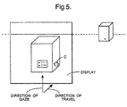
- a data terminal 1 comprises a system unit 2, a monitor 3 and a user input device 4.
- the user input device 4 is a track-ball having six degrees of freedom.
- two mice may be used as the input devices.
- one mouse is a so-called space-ball which moves in 3 dimensions and controls the movement of the viewpoint.
- the other mouse is a conventional 2D input device and is used for clicking on objects in the environment to select them.
- the system unit 2 is connected to a local area network.
- the LAN may include a server (not shown) providing a TCP/IP connection to the Internet.
- the system unit 2 generates and displays on the monitor 3 a perspective view of a three-dimensional environment in which different data sources are represented as objects 01,02 in the environment.
- a cursor C is also displayed on the monitor 3.
- FIG. 2 shows in further detail the components making up the terminal 1.
- a central processor unit (CPU) 5 runs the terminal's operating systems. Suitable processors include the Motorola PowerPC 601 or Mips R4600PC The CPU is connected via an appropriate interface 8 to the LAN. In addition, the CPU accesses local data stored on a mass storage device 9 and in random access memory 10. The operating system for the terminal is stored in ROM 6. This includes OS subsystems for implementing the graphical elements of the user interface. Using these subsystems the CPU 5 and video display card 7 generate a display which is output to the monitor 3.
- the position of the trackball 4 is returned to the CPU 5.
- the values returned are interpreted by the operating system, and any change is converted into a corresponding movement of the cursor C on the display.
- the track ball 4 is used to manipulate the cursor C to locate it at the object 02.
- a double-click operation is performed to select the object.
- the operating system then initiates a transition or flight to the selected object, as described further below.
- the CPU 5 prepares to access the data source associated with the object.
- Figures 3A to 3G are successive frames separated by uniform time intervals illustrating the manner in which the user interface changes the view presented to the user during the flight to the selected object.
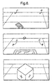
- Figures 4A to 4G are plan views showing the relative location of the viewpoint and of the destination object at corresponding times.
- Figure 3A Shows the view of the object prior to its being selected.
- the direction of gaze shown by the arrow in Figure 4a, is angled away from the object by some 30 degrees.
- 3B Shows the cursor located at the object as the user selects it.
- the direction of gaze of the viewpoint then begins to turn towards the selected object at the same time as the viewpoint is slowly translated towards the object.
- the angle of the direction of gaze has changed to approximately 15 degrees from the object.
- frame 3D the direction of gaze is substantially aligned with the target object which is separated from the viewpoint by distance D, and at this point the speed of translation towards the object is increased. in the following frames, the distance between the viewpoint and the object is halved in each successive frame, so that the object is approached with a progressively diminishing speed.
- the distance between the viewpoint and the object has fallen below a minimum threshold and the viewpoint is treated as having arrived at the object.
- the movement of the viewpoint then stops.
- the CPU accesses the relevant data source and displays it to the user.
- the initial display might comprise, for example, a menu of items available in the data source. This menu might be displayed on or inside the object within the three-D environment.
- arrival at the object might trigger a switch to an alternative display, for example a two-dimensional full-screen window.
- the object is one having the property that it allows the user to enter it, for example to access menus displayed on its inner surfaces, then the walls of the object are arranged to become translucent as seen from the viewpoint inside the object.
- the menus displayed inside the object may include links to other data sources.
- the object acts as a transporter, and selection of an appropriate menu item results in the viewpoint being translated to a different location in the environment, or to an alternative environment.
- the user may scan the environment and view and/or select other objects in the environment, In the example shown in Figure 5, the initial flight takes place as shown in the first four frames of Figure 3. However then a further object comes into view. The user then turns the direction of gaze of the viewpoint towards the further object by moving the cursor to using the track ball. At the same time as the direction of gaze moves away from direction of travel towards the destination object, the speed of movement of the viewpoint towards the object is curtailed to a low fixed level. The direction of gaze remains turned towards the further object, as shown in Figure 5, for as long as that object is selected by the user holding down the track ball button while locating the cursor at the object.
- the further object is an on-line news service including headlines displayed on the outer surface of the object.
- the user may choose the on-line news object as a new destination object by double clicking.
- the user may release the track ball button.
- the operating system turns the direction of gaze of the viewpoint back to the original destination object, increases the speed of travel to the object, and completes the flight to the destination object in the manner described previously with respect to Figure 3.
- the operating systems provides a further alternative method of selecting and accessing data sources.
- This uses vehicle objects which carry the viewpoint to a predetermined location. The user then does. not have to select the destination directly, but instead first selects the vehicle object.
- the vehicle object is represented graphically as a flying carpet.
- the viewpoint is first moved to the vehicle object and the vehicle object and viewpoint then move towards a predetermined destination object associated with the vehicle object.
- this is a data source which was out of sight over the horizon in the starting position of the viewpoint.
- certain landmark objects J1, J2. do not have any corresponding data source, but nonetheless may be selected by the user as a destination to aid navigation through the environment.
- Table 1 below lists code for use in implementing the user interface described above.
- the interface is coded using a commercially available language designed for the manipulation of three-dimensional environments known as SCL.
- SCL three-dimensional environments
- the control/display environment might be constructed using VRML (virtual reality mark- up language) tools such as those contained in the Open Inventor tool kit available commercially from Silicon Graphics Inc. of Mountain View, California, USA.
- VRML virtual reality mark- up language
- the operations making up the user interface may be implemented in hardware.
- a graphic processor chip included in the video card 7 may implement in hardware certain primitive operations of the interface such as the 3-D scrolling of the environment as the viewpoint moves. Object 'eye'.
- This code demonstates navigation in VR space. If the object number of a target object is put in t. I will 'fly' the viewpoint to near the target and set t to me, a second assignment of the target object number to t will take the viewpoint inside the target (where object-specific code can be invoked). (Note: if the viewpoint is already 'close' to me on the first asignment of the target object number to 1, the viewpoint will fly directly inside the target without halting.) Flight is fastest at the start of the flight and slows down as the target object is approached. The speed of flight is also slower when the viewpoint is NOT directed towards the target. This ensures that viewpoint rotations are completed before the target is reached and the user is not disoriented by excessive sideways flying.
- Flight may be stopped at any time by setting t to me (usually by hitting the space bar).
- the code will respond correctly if the target moves or changes size while I am controlling the viewpoint.
- This code relies on my child object 'eyeball' and the viewpoint. I am coupled to 'eyeball'.
- the viewpoint must be attached to 'eyeball' and control 'eye' and have mode 'View No Z 5.
- I the attached viewpoint moves with me.
- Objects may test 'eye'. t to see if they have 'posession' of the viewpoint. This allows objects to avoid unwanted execution of their object-specific code when the viewpoint flies through them on the way to another object.
- t is set to 'eye'.
- Local variables used as contents are: dr controls how close we get to the target before halting fight. (The actual close distance is sqrt(dr)*max(xsize(me), ysize(me), zsize(me)) ).
Claims (13)
- Steuerschnittstelle für ein Datenendgerät, die umfaßt:einen Anzeigegenerator zum Erzeugen eines Ausgangssignals für eine Anzeigevorrichtung einer dreidimensionalen Anzeige einer Umgebung, die mehrere Objekte enthält, die verschiedenen jeweiligen Datenquellen entsprechen, wobei der Anzeigegenerator in Reaktion auf eine Eingabe eines Anwenders über die Anwendereingabevorrichtung so betreibbar ist, daß er den sichtbaren Ort des Standpunkts in der Umgebung von einem momentanen Ort zum Ort eines Zielobjekts allmählich über eine Reihe von Zwischenorten und mit einer Geschwindigkeit, die bei Annäherung an das Zielobjekt progressiv verringert wird, ändert, dadurch gekennzeichnet, daßder Anzeigegenerator ferner in Reaktion auf eine weitere Steuereingabe des Anwenders während der Bewegung des Standpunkts so betreibbar ist, daß er die Blickrichtung des Standpunkts vom Zielobjekt zu einem weiteren Objekt in der Umgebung bewegt und gleichzeitig eine diskontinuierliche Verringerung der Bewegungsgeschwindigkeit zusätzlich zu der progressiven Verringerung in Verbindung mit der Annäherung an das Zielobjekt vornimmt.
- Steuerschnittstelle nach Anspruch 1, bei der die Blickrichtung dann, wenn sie anfangs vom Objekt weggerichtet ist, allmählich und konkurrent mit der Bewegung des Standpunkts zum Zielobjekt so gedreht wird, daß sie auf das Zielobjekt weist.
- Steuerschnittstelle nach Anspruch 2, bei der die Bewegungsgeschwindigkeit des Standpunkts zum Zielobjekt auf einem ersten verhältnismäßig niedrigeren Wert gehalten wird, wenn die Blickrichtung vom Objekt weggerichtet ist, und auf einen zweiten verhältnismäßig höheren Wert erhöht wird, wenn die Blickrichtung zum Objekt gerichtet ist.
- Steuerschnittstelle nach einem der Ansprüche 1 bis 3, bei der die Annäherungsgeschwindigkeit auf einem im wesentlichen konstanten, verringerten Pegel gehalten wird, während die Blickrichtung vom Zielobjekt weggerichtet ist.
- Steuerschnittstelle nach einem der vorhergehenden Ansprüche, die ferner Vehikelobjekte umfaßt, die in der Schnittstellenumgebung angezeigt werden und so beschaffen sind, daß sie, wenn sie vom Anwender gewählt werden, den Standpunkt über eine Reihe von Zwischenorten zum Ort eines vorgegebenen Zielobjekts einnehmen.
- Steuerschnittstelle nach einem der vorhergehenden Ansprüche, die Orientierungspunkt-Objekte, die in der Schnittstellenumgebung angezeigt werden, enthält.
- Verfahren zum Steuern eines Datenendgeräts, das die folgenden Schritte umfaßt:Erzeugen einer Anzeige einer dreidimensionalen Umgebung, die mehrere Objekte enthält, die verschiedenen Datenquellen entsprechen;in Reaktion auf eine Steuereingabe eines Anwenders allmähliches Bewegen des sichtbaren Ortes des Standpunkts in der Umgebung von einem momentanen Ort zum Ort eines Zielobjekts über eine Reihe von Zwischenorten und mit einer Geschwindigkeit, die bei Annäherung an das Zielobjekt progressiv verringert wird, gekennzeichnet durch die folgenden weiteren Schritte:in Reaktion auf eine weitere Steuereingabe des Anwenders während der Bewegung des Standpunkts Orientieren der Blickrichtung des Standpunkts weg vom Zielobjekt und zu einem weiteren Objekt in der Umgebung; undVornehmen einer diskontinuierlichen Verringerung der Bewegungsgeschwindigkeit zusätzlich zu der progressiven Verringerung in Verbindung mit der Annäherung an das Zielobjekt.
- Verfahren nach Anspruch 7, das ferner den Schritt umfaßt, bei dem dann, wenn die Blickrichtung anfangs vom Objekt weggerichtet ist, die Richtung allmählich und konkurrent mit der Bewegung des Standpunkts zum Zielobjekt so gedreht wird, daß sie zum Zielobjekt weist.
- Verfahren nach Anspruch 7 oder 8, bei dem die Bewegungsgeschwindigkeit des Standpunkts zum Zielobjekt auf einem ersten verhältnismäßig niedrigeren Wert gehalten wird, wenn die Blickrichtung vom Objekt weggerichtet ist, und auf einen zweiten verhältnismäßig höheren Wert erhöht wird, wenn die Blickrichtung zum Objekt gerichtet ist.
- Verfahren nach einem der Ansprüche 7 bis 9, bei dem die Annäherungsgeschwindigkeit auf einem im wesentlichen konstanten, verringerten Pegel gehalten wird, während die Blickrichtung vom Zielobjekt weggerichtet ist.
- Verfahren nach einem der Ansprüche 7 bis 10, bei dem in der Schnittstellenumgebung Vehikelobjekte angezeigt werden, die so beschaffen sind, daß sie dann, wenn sie vom Anwender ausgewählt werden, den Standpunkt über eine Reihe von Zwischenorten zu dem Ort eines vorgegebenen Zielobjekts einnehmen.
- Verfahren nach einem der Ansprüche 7 bis 11, bei dem in der Schnittstellenumgebung Orientierungspunkt-Objekte angezeigt werden.
- Computerprogramm oder Folge von Computerprogrammen, die so beschaffen sind, daß sie einen Computer oder eine Gruppe von Computern in die Lage versetzen, die Steuerschnittstelle nach einem der Ansprüche 1 bis 6 zu schaffen und/oder das Verfahren nach einem der Ansprüche 7 bis 12 auszuführen.
Applications Claiming Priority (3)
| Application Number | Priority Date | Filing Date | Title |
|---|---|---|---|
| GB9606791 | 1996-03-29 | ||
| GBGB9606791.3A GB9606791D0 (en) | 1996-03-29 | 1996-03-29 | Control interface |
| PCT/GB1997/000872 WO1997037294A1 (en) | 1996-03-29 | 1997-03-27 | Control interface |
Publications (2)
| Publication Number | Publication Date |
|---|---|
| EP0891579A1 EP0891579A1 (de) | 1999-01-20 |
| EP0891579B1 true EP0891579B1 (de) | 2003-01-02 |
Family
ID=10791367
Family Applications (1)
| Application Number | Title | Priority Date | Filing Date |
|---|---|---|---|
| EP97914469A Expired - Lifetime EP0891579B1 (de) | 1996-03-29 | 1997-03-27 | Steuerschnittstelle |
Country Status (7)
| Country | Link |
|---|---|
| US (1) | US6281877B1 (de) |
| EP (1) | EP0891579B1 (de) |
| JP (1) | JP2000507725A (de) |
| AU (1) | AU2170997A (de) |
| DE (1) | DE69718159T2 (de) |
| GB (1) | GB9606791D0 (de) |
| WO (1) | WO1997037294A1 (de) |
Families Citing this family (24)
| Publication number | Priority date | Publication date | Assignee | Title |
|---|---|---|---|---|
| WO1998045767A2 (en) * | 1997-04-04 | 1998-10-15 | Fred Steven Isom | Method of sequencing computer controlled tasks based on the relative spatial location of task objects in a directional field |
| JPH11154074A (ja) | 1997-11-25 | 1999-06-08 | Sharp Corp | スクロール制御装置 |
| JP4003794B2 (ja) * | 1998-08-07 | 2007-11-07 | 株式会社セガ | 画像処理方法及び画像処理装置 |
| JP2000200361A (ja) | 1998-08-07 | 2000-07-18 | Sega Enterp Ltd | 画像処理装置及び情報記録媒体 |
| JP4019240B2 (ja) * | 1999-05-07 | 2007-12-12 | 株式会社セガ | 画像処理方法、記録媒体及び画像処理装置 |
| DE10016753A1 (de) * | 2000-04-04 | 2001-10-11 | Definiens Ag | Verfahren zum Navigieren zwischen Ausschnitten in einem Darstellungsraum |
| US7263711B1 (en) | 2000-09-18 | 2007-08-28 | Intel Corporation | Terminating enhanced television broadcasts |
| JP4077321B2 (ja) * | 2001-02-23 | 2008-04-16 | 富士通株式会社 | 表示制御装置 |
| US7646394B1 (en) | 2004-03-05 | 2010-01-12 | Hrl Laboratories, Llc | System and method for operating in a virtual environment |
| KR100608589B1 (ko) * | 2004-07-24 | 2006-08-03 | 삼성전자주식회사 | 3차원 모션 그래픽 사용자 인터페이스 및 이를 제공하는방법 및 장치 |
| KR100631763B1 (ko) * | 2004-07-26 | 2006-10-09 | 삼성전자주식회사 | 3차원 모션 그래픽 사용자 인터페이스 및 이를 제공하는방법 및 장치 |
| KR100643276B1 (ko) * | 2004-08-07 | 2006-11-10 | 삼성전자주식회사 | 3차원 모션 그래픽 사용자 인터페이스 및 이를 제공하는방법 및 장치 |
| KR100755684B1 (ko) * | 2004-08-07 | 2007-09-05 | 삼성전자주식회사 | 3차원 모션 그래픽 사용자 인터페이스 및 이를 제공하는방법 및 장치 |
| US8730156B2 (en) | 2010-03-05 | 2014-05-20 | Sony Computer Entertainment America Llc | Maintaining multiple views on a shared stable virtual space |
| US9250703B2 (en) | 2006-03-06 | 2016-02-02 | Sony Computer Entertainment Inc. | Interface with gaze detection and voice input |
| US8793620B2 (en) * | 2011-04-21 | 2014-07-29 | Sony Computer Entertainment Inc. | Gaze-assisted computer interface |
| JP4384697B2 (ja) * | 2008-03-26 | 2009-12-16 | 株式会社コナミデジタルエンタテインメント | ゲーム装置、ゲーム処理方法、ならびに、プログラム |
| US20100045666A1 (en) * | 2008-08-22 | 2010-02-25 | Google Inc. | Anchored Navigation In A Three Dimensional Environment On A Mobile Device |
| US20100100853A1 (en) * | 2008-10-20 | 2010-04-22 | Jean-Pierre Ciudad | Motion controlled user interface |
| US20150169119A1 (en) * | 2010-02-17 | 2015-06-18 | Google Inc. | Major-Axis Pinch Navigation In A Three-Dimensional Environment On A Mobile Device |
| JP2012190183A (ja) * | 2011-03-09 | 2012-10-04 | Sony Corp | 画像処理装置および方法、並びにプログラム |
| JP2012190184A (ja) * | 2011-03-09 | 2012-10-04 | Sony Corp | 画像処理装置および方法、並びにプログラム |
| US10120438B2 (en) | 2011-05-25 | 2018-11-06 | Sony Interactive Entertainment Inc. | Eye gaze to alter device behavior |
| US10585485B1 (en) | 2014-11-10 | 2020-03-10 | Amazon Technologies, Inc. | Controlling content zoom level based on user head movement |
Family Cites Families (10)
| Publication number | Priority date | Publication date | Assignee | Title |
|---|---|---|---|---|
| US4812829A (en) * | 1986-05-17 | 1989-03-14 | Hitachi, Ltd. | Three-dimensional display device and method for pointing displayed three-dimensional image |
| US5359703A (en) * | 1990-08-02 | 1994-10-25 | Xerox Corporation | Moving an object in a three-dimensional workspace |
| US5276785A (en) * | 1990-08-02 | 1994-01-04 | Xerox Corporation | Moving viewpoint with respect to a target in a three-dimensional workspace |
| US5333254A (en) * | 1991-10-02 | 1994-07-26 | Xerox Corporation | Methods of centering nodes in a hierarchical display |
| US5675746A (en) * | 1992-09-30 | 1997-10-07 | Marshall; Paul S. | Virtual reality generator for use with financial information |
| US5689628A (en) * | 1994-04-14 | 1997-11-18 | Xerox Corporation | Coupling a display object to a viewpoint in a navigable workspace |
| WO1995029465A1 (en) * | 1994-04-21 | 1995-11-02 | Sandia Corporation | Multi-dimensional user oriented synthetic environment |
| US5812142A (en) * | 1994-09-30 | 1998-09-22 | Apple Computer, Inc. | Motion movement cueing through synchronized display port and image |
| US5956028A (en) * | 1995-09-14 | 1999-09-21 | Fujitsu Ltd. | Virtual space communication system, three-dimensional image display method, and apparatus therefor |
| US5808613A (en) * | 1996-05-28 | 1998-09-15 | Silicon Graphics, Inc. | Network navigator with enhanced navigational abilities |
-
1996
- 1996-03-29 GB GBGB9606791.3A patent/GB9606791D0/en active Pending
-
1997
- 1997-03-27 JP JP9535030A patent/JP2000507725A/ja active Pending
- 1997-03-27 DE DE69718159T patent/DE69718159T2/de not_active Expired - Lifetime
- 1997-03-27 US US09/029,576 patent/US6281877B1/en not_active Expired - Fee Related
- 1997-03-27 EP EP97914469A patent/EP0891579B1/de not_active Expired - Lifetime
- 1997-03-27 WO PCT/GB1997/000872 patent/WO1997037294A1/en active IP Right Grant
- 1997-03-27 AU AU21709/97A patent/AU2170997A/en not_active Abandoned
Also Published As
| Publication number | Publication date |
|---|---|
| EP0891579A1 (de) | 1999-01-20 |
| DE69718159D1 (de) | 2003-02-06 |
| US6281877B1 (en) | 2001-08-28 |
| GB9606791D0 (en) | 1996-06-05 |
| AU2170997A (en) | 1997-10-22 |
| DE69718159T2 (de) | 2003-11-13 |
| JP2000507725A (ja) | 2000-06-20 |
| WO1997037294A1 (en) | 1997-10-09 |
Similar Documents
| Publication | Publication Date | Title |
|---|---|---|
| EP0891579B1 (de) | Steuerschnittstelle | |
| JP7123148B2 (ja) | 複合現実ディスプレイにおける仮想コンテンツのための掩蔽カーソル | |
| US7148892B2 (en) | 3D navigation techniques | |
| US6144381A (en) | Systems, methods and computer program products for compass navigation of avatars in three dimensional worlds | |
| Rekimoto et al. | The information cube: Using transparency in 3d information visualization | |
| Jankowski et al. | A survey of interaction techniques for interactive 3D environments | |
| JP3928229B2 (ja) | 表示制御装置および表示制御方法、並びに記録媒体 | |
| WO2019236344A1 (en) | Augmented reality scrollbar | |
| US5608850A (en) | Transporting a display object coupled to a viewpoint within or between navigable workspaces | |
| KR100324878B1 (ko) | 가상현실환경에서정보를표시하는방법 | |
| US7278115B1 (en) | Methods, apparatus and data structures for providing a user interface to objects, the user interface exploiting spatial memory and visually indicating at least one object parameter | |
| US5956039A (en) | System and method for increasing performance by efficient use of limited resources via incremental fetching, loading and unloading of data assets of three-dimensional worlds based on transient asset priorities | |
| US20230152936A1 (en) | 3D Interactions with Web Content | |
| KR20010030859A (ko) | 컴퓨터 자원을 제어하도록 동작하는 운영 체제와 상호작용하기 위한 장치 및 방법 | |
| Darken | Hands-off interaction with menus in virtual spaces | |
| Jaswa | CAVEvis: Distributed real-time visualization of time-varying scalar and vector fields using the CAVE virtual reality theater | |
| Pichler et al. | VRweb: a multi-system VRML viewer | |
| Schmalstieg | Augmented reality techniques in games | |
| Eyl | The harmony information landscape: interactive, three-dimensional navigation through an information space | |
| Bönsch et al. | Enhancing Proxy Localization in World in Miniatures Focusing on Virtual Agents | |
| Ball et al. | A prototype Hotel Browsing system using Java3D | |
| Flasar et al. | Manipulating objects behind obstacles | |
| TA | 5.2. 1 Homogeneous Transformation Matrices |
Legal Events
| Date | Code | Title | Description |
|---|---|---|---|
| PUAI | Public reference made under article 153(3) epc to a published international application that has entered the european phase |
Free format text: ORIGINAL CODE: 0009012 |
|
| 17P | Request for examination filed |
Effective date: 19980717 |
|
| AK | Designated contracting states |
Kind code of ref document: A1 Designated state(s): BE CH DE DK ES FI FR GB IE IT LI NL PT SE |
|
| 17Q | First examination report despatched |
Effective date: 20001123 |
|
| GRAG | Despatch of communication of intention to grant |
Free format text: ORIGINAL CODE: EPIDOS AGRA |
|
| GRAG | Despatch of communication of intention to grant |
Free format text: ORIGINAL CODE: EPIDOS AGRA |
|
| GRAH | Despatch of communication of intention to grant a patent |
Free format text: ORIGINAL CODE: EPIDOS IGRA |
|
| GRAH | Despatch of communication of intention to grant a patent |
Free format text: ORIGINAL CODE: EPIDOS IGRA |
|
| GRAA | (expected) grant |
Free format text: ORIGINAL CODE: 0009210 |
|
| AK | Designated contracting states |
Kind code of ref document: B1 Designated state(s): BE CH DE DK ES FI FR GB IE IT LI NL PT SE |
|
| PG25 | Lapsed in a contracting state [announced via postgrant information from national office to epo] |
Ref country code: NL Free format text: LAPSE BECAUSE OF FAILURE TO SUBMIT A TRANSLATION OF THE DESCRIPTION OR TO PAY THE FEE WITHIN THE PRESCRIBED TIME-LIMIT Effective date: 20030102 Ref country code: LI Free format text: LAPSE BECAUSE OF FAILURE TO SUBMIT A TRANSLATION OF THE DESCRIPTION OR TO PAY THE FEE WITHIN THE PRESCRIBED TIME-LIMIT Effective date: 20030102 Ref country code: IT Free format text: LAPSE BECAUSE OF FAILURE TO SUBMIT A TRANSLATION OF THE DESCRIPTION OR TO PAY THE FEE WITHIN THE PRESCRIBED TIME-LIMIT;WARNING: LAPSES OF ITALIAN PATENTS WITH EFFECTIVE DATE BEFORE 2007 MAY HAVE OCCURRED AT ANY TIME BEFORE 2007. THE CORRECT EFFECTIVE DATE MAY BE DIFFERENT FROM THE ONE RECORDED. Effective date: 20030102 Ref country code: FI Free format text: LAPSE BECAUSE OF FAILURE TO SUBMIT A TRANSLATION OF THE DESCRIPTION OR TO PAY THE FEE WITHIN THE PRESCRIBED TIME-LIMIT Effective date: 20030102 Ref country code: CH Free format text: LAPSE BECAUSE OF FAILURE TO SUBMIT A TRANSLATION OF THE DESCRIPTION OR TO PAY THE FEE WITHIN THE PRESCRIBED TIME-LIMIT Effective date: 20030102 Ref country code: BE Free format text: LAPSE BECAUSE OF FAILURE TO SUBMIT A TRANSLATION OF THE DESCRIPTION OR TO PAY THE FEE WITHIN THE PRESCRIBED TIME-LIMIT Effective date: 20030102 |
|
| REG | Reference to a national code |
Ref country code: GB Ref legal event code: FG4D Free format text: 20030102 |
|
| REG | Reference to a national code |
Ref country code: CH Ref legal event code: EP |
|
| REG | Reference to a national code |
Ref country code: IE Ref legal event code: FG4D |
|
| REF | Corresponds to: |
Ref document number: 69718159 Country of ref document: DE Date of ref document: 20030206 Kind code of ref document: P |
|
| PG25 | Lapsed in a contracting state [announced via postgrant information from national office to epo] |
Ref country code: IE Free format text: LAPSE BECAUSE OF NON-PAYMENT OF DUE FEES Effective date: 20030327 |
|
| PG25 | Lapsed in a contracting state [announced via postgrant information from national office to epo] |
Ref country code: SE Free format text: LAPSE BECAUSE OF FAILURE TO SUBMIT A TRANSLATION OF THE DESCRIPTION OR TO PAY THE FEE WITHIN THE PRESCRIBED TIME-LIMIT Effective date: 20030402 Ref country code: PT Free format text: LAPSE BECAUSE OF FAILURE TO SUBMIT A TRANSLATION OF THE DESCRIPTION OR TO PAY THE FEE WITHIN THE PRESCRIBED TIME-LIMIT Effective date: 20030402 Ref country code: DK Free format text: LAPSE BECAUSE OF FAILURE TO SUBMIT A TRANSLATION OF THE DESCRIPTION OR TO PAY THE FEE WITHIN THE PRESCRIBED TIME-LIMIT Effective date: 20030402 |
|
| REG | Reference to a national code |
Ref country code: CH Ref legal event code: PL |
|
| PG25 | Lapsed in a contracting state [announced via postgrant information from national office to epo] |
Ref country code: ES Free format text: LAPSE BECAUSE OF FAILURE TO SUBMIT A TRANSLATION OF THE DESCRIPTION OR TO PAY THE FEE WITHIN THE PRESCRIBED TIME-LIMIT Effective date: 20030730 |
|
| ET | Fr: translation filed | ||
| PLBE | No opposition filed within time limit |
Free format text: ORIGINAL CODE: 0009261 |
|
| STAA | Information on the status of an ep patent application or granted ep patent |
Free format text: STATUS: NO OPPOSITION FILED WITHIN TIME LIMIT |
|
| 26N | No opposition filed |
Effective date: 20031003 |
|
| REG | Reference to a national code |
Ref country code: IE Ref legal event code: MM4A |
|
| PGFP | Annual fee paid to national office [announced via postgrant information from national office to epo] |
Ref country code: FR Payment date: 20120403 Year of fee payment: 16 |
|
| PGFP | Annual fee paid to national office [announced via postgrant information from national office to epo] |
Ref country code: DE Payment date: 20120323 Year of fee payment: 16 |
|
| REG | Reference to a national code |
Ref country code: FR Ref legal event code: ST Effective date: 20131129 |
|
| REG | Reference to a national code |
Ref country code: DE Ref legal event code: R119 Ref document number: 69718159 Country of ref document: DE Effective date: 20131001 |
|
| PG25 | Lapsed in a contracting state [announced via postgrant information from national office to epo] |
Ref country code: FR Free format text: LAPSE BECAUSE OF NON-PAYMENT OF DUE FEES Effective date: 20130402 Ref country code: DE Free format text: LAPSE BECAUSE OF NON-PAYMENT OF DUE FEES Effective date: 20131001 |
|
| PGFP | Annual fee paid to national office [announced via postgrant information from national office to epo] |
Ref country code: GB Payment date: 20160321 Year of fee payment: 20 |
|
| REG | Reference to a national code |
Ref country code: GB Ref legal event code: PE20 Expiry date: 20170326 |
|
| PG25 | Lapsed in a contracting state [announced via postgrant information from national office to epo] |
Ref country code: GB Free format text: LAPSE BECAUSE OF EXPIRATION OF PROTECTION Effective date: 20170326 |