EP0891021A2 - An apparatus for processing information of a wiring harness - Google Patents
An apparatus for processing information of a wiring harness Download PDFInfo
- Publication number
- EP0891021A2 EP0891021A2 EP98305408A EP98305408A EP0891021A2 EP 0891021 A2 EP0891021 A2 EP 0891021A2 EP 98305408 A EP98305408 A EP 98305408A EP 98305408 A EP98305408 A EP 98305408A EP 0891021 A2 EP0891021 A2 EP 0891021A2
- Authority
- EP
- European Patent Office
- Prior art keywords
- wiring
- information
- accordance
- wiring harness
- connectors
- Prior art date
- Legal status (The legal status is an assumption and is not a legal conclusion. Google has not performed a legal analysis and makes no representation as to the accuracy of the status listed.)
- Granted
Links
Images


Classifications
-
- H—ELECTRICITY
- H01—ELECTRIC ELEMENTS
- H01R—ELECTRICALLY-CONDUCTIVE CONNECTIONS; STRUCTURAL ASSOCIATIONS OF A PLURALITY OF MUTUALLY-INSULATED ELECTRICAL CONNECTING ELEMENTS; COUPLING DEVICES; CURRENT COLLECTORS
- H01R43/00—Apparatus or processes specially adapted for manufacturing, assembling, maintaining, or repairing of line connectors or current collectors or for joining electric conductors
- H01R43/28—Apparatus or processes specially adapted for manufacturing, assembling, maintaining, or repairing of line connectors or current collectors or for joining electric conductors for wire processing before connecting to contact members, not provided for in groups H01R43/02 - H01R43/26
-
- G—PHYSICS
- G06—COMPUTING; CALCULATING OR COUNTING
- G06F—ELECTRIC DIGITAL DATA PROCESSING
- G06F2113/00—Details relating to the application field
- G06F2113/16—Cables, cable trees or wire harnesses
-
- Y—GENERAL TAGGING OF NEW TECHNOLOGICAL DEVELOPMENTS; GENERAL TAGGING OF CROSS-SECTIONAL TECHNOLOGIES SPANNING OVER SEVERAL SECTIONS OF THE IPC; TECHNICAL SUBJECTS COVERED BY FORMER USPC CROSS-REFERENCE ART COLLECTIONS [XRACs] AND DIGESTS
- Y10—TECHNICAL SUBJECTS COVERED BY FORMER USPC
- Y10T—TECHNICAL SUBJECTS COVERED BY FORMER US CLASSIFICATION
- Y10T29/00—Metal working
- Y10T29/49—Method of mechanical manufacture
- Y10T29/49002—Electrical device making
- Y10T29/49117—Conductor or circuit manufacturing
- Y10T29/49124—On flat or curved insulated base, e.g., printed circuit, etc.
- Y10T29/49155—Manufacturing circuit on or in base
- Y10T29/49163—Manufacturing circuit on or in base with sintering of base
-
- Y—GENERAL TAGGING OF NEW TECHNOLOGICAL DEVELOPMENTS; GENERAL TAGGING OF CROSS-SECTIONAL TECHNOLOGIES SPANNING OVER SEVERAL SECTIONS OF THE IPC; TECHNICAL SUBJECTS COVERED BY FORMER USPC CROSS-REFERENCE ART COLLECTIONS [XRACs] AND DIGESTS
- Y10—TECHNICAL SUBJECTS COVERED BY FORMER USPC
- Y10T—TECHNICAL SUBJECTS COVERED BY FORMER US CLASSIFICATION
- Y10T29/00—Metal working
- Y10T29/49—Method of mechanical manufacture
- Y10T29/49002—Electrical device making
- Y10T29/49117—Conductor or circuit manufacturing
- Y10T29/49174—Assembling terminal to elongated conductor
- Y10T29/49181—Assembling terminal to elongated conductor by deforming
-
- Y—GENERAL TAGGING OF NEW TECHNOLOGICAL DEVELOPMENTS; GENERAL TAGGING OF CROSS-SECTIONAL TECHNOLOGIES SPANNING OVER SEVERAL SECTIONS OF THE IPC; TECHNICAL SUBJECTS COVERED BY FORMER USPC CROSS-REFERENCE ART COLLECTIONS [XRACs] AND DIGESTS
- Y10—TECHNICAL SUBJECTS COVERED BY FORMER USPC
- Y10T—TECHNICAL SUBJECTS COVERED BY FORMER US CLASSIFICATION
- Y10T29/00—Metal working
- Y10T29/53—Means to assemble or disassemble
- Y10T29/5313—Means to assemble electrical device
- Y10T29/532—Conductor
- Y10T29/53209—Terminal or connector
- Y10T29/53213—Assembled to wire-type conductor
- Y10T29/53217—Means to simultaneously assemble multiple, independent conductors to terminal
-
- Y—GENERAL TAGGING OF NEW TECHNOLOGICAL DEVELOPMENTS; GENERAL TAGGING OF CROSS-SECTIONAL TECHNOLOGIES SPANNING OVER SEVERAL SECTIONS OF THE IPC; TECHNICAL SUBJECTS COVERED BY FORMER USPC CROSS-REFERENCE ART COLLECTIONS [XRACs] AND DIGESTS
- Y10—TECHNICAL SUBJECTS COVERED BY FORMER USPC
- Y10T—TECHNICAL SUBJECTS COVERED BY FORMER US CLASSIFICATION
- Y10T29/00—Metal working
- Y10T29/53—Means to assemble or disassemble
- Y10T29/5313—Means to assemble electrical device
- Y10T29/53252—Means to simultaneously fasten three or more parts
-
- Y—GENERAL TAGGING OF NEW TECHNOLOGICAL DEVELOPMENTS; GENERAL TAGGING OF CROSS-SECTIONAL TECHNOLOGIES SPANNING OVER SEVERAL SECTIONS OF THE IPC; TECHNICAL SUBJECTS COVERED BY FORMER USPC CROSS-REFERENCE ART COLLECTIONS [XRACs] AND DIGESTS
- Y10—TECHNICAL SUBJECTS COVERED BY FORMER USPC
- Y10T—TECHNICAL SUBJECTS COVERED BY FORMER US CLASSIFICATION
- Y10T29/00—Metal working
- Y10T29/53—Means to assemble or disassemble
- Y10T29/53796—Puller or pusher means, contained force multiplying operator
- Y10T29/53839—Puller or pusher means, contained force multiplying operator having percussion or explosive operator
- Y10T29/53843—Tube, sleeve, or ferrule inserting or removing
Definitions
- This invention relates an apparatus and a method for generating a wiring harness diagram used for manufacturing of wiring harnesses, more specifically, an improvement of generating thereof such as simplification and easy variation in design.
- the operator obtains a desired wiring arrangement diagram by using an entity input means and an numeral value input means with referring to entities and length information displayed on a display means while generating wiring harness information including a total length of the wiring between each connector in the desired wiring arrangement in accordance with the entities and the length information of the desired wiring arrangement. Therefore, it is possible to generate the wiring harness information including a total length of the wiring between each connector easily as well as inputting the desired wiring arrangement with referring to the displays.
- connection information representing connections between each of the connectors are inputted to the apparatus of the present invention. In this way, the wiring harness information including connections between the connectors can easily be generated.
- connection information are inputted from an apparatus for designing circuits in the apparatus of the present invention. It is therefore possible to use the connection information being used during the design work with the apparatus of the present invention.
- an entity representing a connection between the connectors is also inputted in the apparatus of the present invention.
- a desired wiring arrangement can be inputted while displaying connections between the connectors on a display screen.
- the wiring harness information for outputting a wiring diagram illustrated in actual lengths of the wirings are generated in accordance with the entities and the length information. Therefore, it is possible to obtain a wiring substrate fixing the wiring diagram thereon illustrated in actual size by nailing the wiring diagram on the substrate at a proper position.
- a wiring arrangement diagram not illustrating actual length of the wirings is displayed on the display device while outputting the wiring diagram illustrating actual length of the wiring from a printing device.
- the wiring diagram can easily be previewed on the display screen while obtaining the wiring diagram illustrated in actual size on a paper.
- the wiring harness information of an independent wiring harness being connected each other as a group are generated in accordance with the entities and the length information. Therefore, it is possible to obtain an independent wiring harness diagram or the like by just inputting an overall wiring arrangement diagram.
- the wiring harness information of the independent wiring harnesses including the connection information of each terminal between each connector are generated by additionally considering the connection information of each terminal between each of the connectors thus inputted. It is therefore possible to generate the independent harness diagram illustrating in greater details.
- connection information of each terminal between each of the connectors corresponds to the entity representing the connector, binding part and the wiring. In this way, it is possible to recognize details of the connection data easily.
- a judgement is carried out whether or not connection status of wiring in the independent wiring harness being extracted comply with a predetermined rule. It is therefore possible to judge whether or not the independent wiring harness which will be extracted comply with the predetermined rule by just inputting the overall wiring arrangement diagram. As a result, the independence wiring harness which does not comply with the rule can be rejected during the generation of the overall wiring arrangement diagram.
- correction of a given length of the wiring is performed by considering a length of displacement in actual wiring work as a correction value.
- the wiring harness having accurate length can be obtained in consideration of the length of displacement in the actual wiring work.
- the correction value at least includes a length caused by displacement of the wiring work or a margin for crimping the connector terminals. It is therefore possible to avoid displacement caused by the wiring work or the margin for crimping the connector terminals both having a great influence of the displacement during the actual wiring work.
- a part of the wiring harness information are provided to a wiring harness manufacturing device, the part of the wiring harness information being used in the wiring harness manufacturing device. In this way, data used in the wiring harness manufacturing device can be set automatically.
- the wiring harness diagram is generated by performing the steps of: displaying connector and binding part on a display screen and connecting therebetween with wiring as well as providing connection data between each connector, providing a length of the wiring connecting the connectors and the binding parts, and outputting the independent wiring harness diagram being connected each other as a group in accordance with the wiring arrangement diagram and the length of the wiring. It is therefore possible to obtain the independent harness diagram easily while inputting a predetermined wiring arrangement with referring to the displays on the display screen.
- a substrate for wiring is manufactured by performing the steps of: directly drawing a wiring diagram in actual size on the substrate or fixing a sheet illustrating the wiring diagram in actual size on the substrate, and disposing a supporting member for wiring at least a position of locating a binding part in the wiring diagram. In this way, position for disposing the supporting members to each binding part can be determined easily and accurately.
- a method for manufacturing a wiring harness using a computer comprises steps of: inputting entities representing connectors, binding parts, wirings length information of the wirings from an input device, inputting a desired wiring arrangement from the input device with referring to a wiring arrangement diagram generated in basis of the entities and the length information and displayed on a display device, and making the wiring harness using information including a total length of the wiring between each connectors, the harness information being generated in basis of the entities and the length information of the desired wiring arrangement. It is therefore possible to make the manufacturing process easier as a result of easily obtaining the wiring harness information including a total length of the wiring between each connector as well as inputting the desired wiring arrangement with referring to the displays.
- the wiring harness information are generated by additionally considering the connection information of each terminal between each of the connectors being inputted from an apparatus for designing circuits. In this way, the connection information being used during the design work can be also used in the manufacturing processes.
- Entity input means is means for inputting instructions for arranging at least entities representing connectors, binding parts and wirings.
- the entity input means includes not only a mouse or a tracker ball, but also includes other devices such as cursor keys of a keyboard.
- the mouse 2 corresponds to the entity input means.
- numeral value input means is means for inputting lengths of the wirings relatedly with at least each of the entities representing the wirings.
- the numeral value input means includes not only the keyboard, but also the mouse or the tracker ball by which the numeral value displayed on the screen is selected. In the embodiments will be described hereunder, the keyboard 4 corresponds the numeral value input means.
- Wiring harness information means information about wiring harness including at least a total length of the wiring between the connectors.
- Wiring harness information includes any form of information, such as drawings numeral values or characters. Further, the phrase “total lengths of the wirings between the connectors” mentioned above include the lengths represented in the form of numeral values, actual lengths (actual sizes, or reduced sizes, enlarged sizes and in numeral values) in illustrated in drawings or the like.
- a wiring length table shown in Fig. 10 wiring table illustrated in both Figs. 13 and 19, an independent wiring harness diagram shown in Fig. 16 and a wiring diagram illustrated in Fig. 30 corresponds to the "wiring harness information" respectively.
- step S2, step S4, step S4, step S5, step S6 and step S7 shown in Figs. 3 and 22 corresponds to the "wiring harness information generating means".
- Wiring is a line for connecting between connectors, and includes an electric cable, a fiber or the like.
- Apparatus for designing circuits is an apparatus for designing circuits, and the apparatus is at least capable of outputting connection information of the connectors.
- Fig. 1 is a block diagram illustrating overall structure of an embodiment of an apparatus for processing information to manufacture wiring harnesses in the present invention.
- Fig. 2 is a diagram illustrating hardware structure of the apparatus shown in Fig. 1 using a CPU and peripherals.
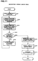
- Fig. 3 is a flow chart showing overall procedures of a program for processing the information of the wiring harnesses.
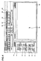
- Fig. 4 is a view illustrating a display screen for inputting a wiring arrangement diagram.
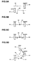
- Fig. 5A is a view illustrating an input of the wiring arrangement diagram.
- Fig. 5B is a view illustrating relocation of the input shown in Fig. 5A.
- Fig. 5C is a view illustrating relocation of the input shown in Fig. 5B.
- Fig. 5D is a view illustrating relocation of the input shown in Fig. 5C.
- Fig. 6A is a view illustrating a dialogue for inputting details of connectors, a type of the wire(s) and other information.
- Fig. 6B is a view illustrating another dialogue for inputting information.
- Fig. 7 is a view illustrating another dialogue for inputting information.
- Fig. 8 is an example of a wiring arrangement diagram thus inputted.
- Fig. 9 is a flow chart showing procedures for processing a table for illustrating length of wiring.
- Fig. 10A is a view illustrating a table for showing length of wiring.
- Fig. 10B is another view illustrating the table for showing length of wiring.
- Fig. 10C is another view illustrating the table for showing length of wiring.
- Fig. 10D is another view illustrating the table for showing length of wiring.
- Fig. 11 a flow chart showing procedures for generating the table for illustrating length of wiring.
- Fig. 12 is a flow chart for generating a part of a wiring table as to a designated (referenced) connector.
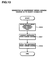
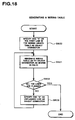
- Fig. 13 is a flow chart for generating an independent wiring harness diagram as to remarked connector.
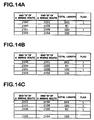
- Fig. 14A is a view illustrating a wiring table.
- Fig. 14B is another view illustrating the wiring table.
- Fig. 14C is another view illustrating the wiring table.
- Fig. 15 is an example of connections of the wiring harness which not comply with a predetermined rule.
- Fig. 16 is an example of the wiring table thus completed.
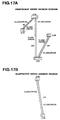
- Fig. 17A is a view illustrating the independent wiring harness.
- Fig. 17B is another view illustrating the independent wiring harness.
- Fig. 18 is a flow chart showing procedures for generating the wiring table.
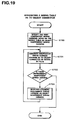
- Fig. 19 is another flow chat showing procedures for generating another wiring table as to the remarked connector.
- Fig. 20 is another example of the wiring table.
- Fig. 21 is a block diagram illustrating another overall structure of a second embodiment of an apparatus for processing information to manufacture the wiring harnesses in the present invention.
- Fig. 22 is another diagram illustrating hardware structure of the apparatus shown in Fig. 20 using the CPU and peripherals.
- Fig. 23 is a flow chart showing overall procedures of a program for processing the information of the wiring harnesses.
- Fig. 24 is another example of the wiring arrangement diagram thus inputted.
- Fig. 25 is an example of a connection information table.
- Fig. 26 is a flow chart for showing procedures for generating a wiring length table.
- Fig. 27 is a view illustrating a display screen for inputting a connection information table.
- Fig. 28 is a flow chart showing procedures for converting the wiring arrangement diagram into actual sizes.
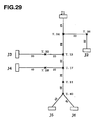
- Fig. 29 is a view illustrating a wiring arrangement diagram displayed on the display screen.
- Fig. 30 is a view showing contents of a list.
- Fig. 31 is a view illustrating the wiring diagram which represents actual length of the wiring harness.
- Fig. 1 is a block diagram illustrating overall structure of an embodiment of an apparatus for processing information of wiring harnesses in the present invention.
- Entities representing connectors, binding parts and wirings are stored in basic entities storing means 16. Further, other entity representing connection between the connectors being connected each other is also stored in the basic entities storing means 16.
- a entity input means 2 is means for inputting, arranging and connecting the entities by selecting the entities stored in the basic entities storing means 16.
- Numeral value input means 4 is means for inputting numeral value and character to relate with each of the entities described above. For instance, the numeral value input means 4 is used for assigning codes to the connectors and for specifying a length of the wiring between the connectors.
- Wiring arrangement diagram generating means 8 generates a wiring arrangement diagram in accordance with the entities, the numeral value and the character thus inputted.
- the wiring arrangement diagram thus generated is displayed on a display means 6.
- a desired wiring arrangement diagram is obtained by carrying out modifications and/or additional input by an operator of the apparatus via the entity input means 2 and/or the numeral value input means 4 while watching the display means 6.
- a wiring table and a diagram of an independent wiring harness (hereinafter referred to as independent wiring harness diagram) as information of wiring harness are generated in accordance with the entities, the numeral value and the character in the desired wiring arrangement diagram with consideration of connection between terminals of each connector by a wiring harness information generating means 10.
- judging means 12 judges whether or not the diagram of the independent wiring harness thus generated complies with a predetermined rule.
- the wiring table and the diagram of the independent wiring harness thus generated are outputted with the a printer 14.
- both the wiring table and the independent wiring harness diagram can be obtained by inputting the wiring arrangement diagram. Further, the judgement can be obtained whether or not the diagram of the independent wiring harness thus generated comply with the rule.
- Fig. 2 is a diagram illustrating hardware structure using a CPU embodying the means shown in Fig. 1.
- a mouse 2, a keyboard 4, a display 6, the printer 14, a hard disk 20, a memory 24 and a flexible disk drive 26 (FDD) are connected to the CPU 22.
- FDD flexible disk drive
- Programs for the operating system such as WindowsTM 95 of Microsoft Corp. and the like are stored in the hard disk 20.
- the operating system carry out the basic controls of the entire system such as displaying, printing, inputting and outputting of data.
- another program for processing the information of wiring harness is stored in the hard disk 20.
- the program is installed in the hard disk 20 from flexible disk(s) through the FDD 26.
- the program may be downloaded into the hard disk 20 through a communication line.
- the program for processing the wiring harness information stored in the flexible disk(s) 28 may be executed directly on the CPU 22 or may be executed after decompressing. Further, the program includes a program which can be executed by combining with the operating system or function(s) of other program(s). For instance, a program for computer-aided design (hereinafter referred to as CAD) generally used for graphics can be used in order to perform processing of graphics in the apparatus. In addition, the program may be a program which executes all the functions by itself.
- CAD computer-aided design
- Fig. 3 is a flow chart showing overall procedures of the program for generating the information of wiring harness.
- a wiring arrangement diagram is inputted in step S1.
- the wiring arrangement diagram is generated by the CPU 22 in accordance with input of the operator through the mouse 2 and the keyboard 4.
- Fig. 4 shows a display screen of the display 6 for inputting the wiring arrangement diagram.
- a work window 32 is an area for generating the wiring arrangement diagram.
- a basic entities window 34 is an area for displaying icons representing the basic entities stored in the hard disk 20.
- icons 38, 40, 42, 44, 46 and 48 respectively representing an electric cable forming the wiring, the connector, a binding belt forming the binding portion, the connection, a round type terminal, a closed type terminal and a flat type terminal are displayed on the basic entities window 34.
- the icons 38 through 48 of the basic entities are allocated on the work window 32 by dragging the icons with control of the cursor position of the mouse 2. In this way, a desired wiring arrangement diagram is generated on the display screen. Processing for each of the entities is similar to that of ordinary CAD applications.
- Figs. 5A through 5D show an example of procedures for generating the wiring arrangement diagram.
- basic entities needed for generating the diagram are allocated on the work window 32 by selection as shown in Fig. 5A.
- the connectors 50 and 52, an electric cable 54, a connection 56 and the binding belt 58 are selected.
- Identifiers are automatically provided to each of the entities thus selected.
- Each of the identifiers is consist of "name of the entity . serial number of the part”.
- identifiers such as "connector. 1", “connector . 2", “electric cable . 1", “connection . 1” and "binding belt . 1" are provided. These identifiers thus provided are stored in the memory 24 and are not displayed on the display screen.
- Additional codes can be provided to the connectors beside the identifiers being provided for the CPU 22 by the operator of the apparatus.
- the additional codes are provided by inputting the codes with the keyboard 4 so as to relate with selected entities after clicking a code input icon 60 for selecting the entities.
- Additional codes such as "J2080M” and "J51B” are respectively provided to the connector 52 and the connector 50 in Figs. 5A through 5D. These codes are respectively displayed adjacent to the related entities on the display screen of the display 6 as well as storing in the memory 24.
- a desired wiring arrangement diagram is generated by connecting each of the entities with the electric cable after moving the positions of the entities.
- one end of the electric cable 54 is connected to the connector 50, and the other end thereof is connected to the connector 52.
- the length of the electric cable 54 can be varied under control of the mouse 2. Both ends of the electric cable 54 are connected to the connectors 50, 52 by adjusting the length thereof.
- the apparatus is controlled to display both ends of the electric cable 54 in red when the both ends thereof are connected to the connectors 50, 52. In this way, the both ends of the electric cable 54 are reliably connected to the connectors 51, 52.
- the binding belt 58 is allocated as shown in Fig. 5B. Further, an actual length "50" of the electric cable 54 from the connector 50 to the binding belt 58 is inputted with the keyboard 4 after clicking another icon 62 for inputting the length shown in Fig. 4. An actual length "60" of the electric cable 54 from the connector 52 to the binding belt 58 is inputted in similar manner. These length are stored in the memory 24 so as to relate with the electric cable 5, and that are displayed on the display screen as shown in Fig. 5C.
- a positional relation among the connector 50, the binding belt 58 and the connector 52 are determined by moving the connector 52 on the display screen as shown in Fig. 5D.
- connection 56 is used for connecting therebetween.
- the connection 56 is displayed in a certain color (or a certain type of line) capable of being clearly distinguished from the electric cable 54.
- properties of the connector 50, 52 and 53, and the connections 56 and 57 are inputted through the keyboard 4.
- the input of these properties are carried out by clicking an icon 64 for inputting properties after selecting the entities.
- a dialogue display for inputting the properties shown in Fig. 6A is displayed on the screen by clicking the icon 64.
- Type, number of terminals, parts number and color of the connector are inputted in the dialogue display.
- "name of connector - terminal number” are displayed on the "remarked connector” column and stored in the hard-disk 20 as a result of processing by the CPU 22.
- Such as "J51B-1", “J51B-2” and “J51B-3" are displayed in Fig. 6A.
- Name of the connector and the terminal being connected to the first terminal of the remarked connector (“J51B-1") is inputted by the operator through the keyboard 4.
- the name of the connector being connected to the remarked connector is hereinafter referred to as an opponent connector.
- connection 54 properties of both the connection 54 and the connector 52 are inputted.
- the CPU 22 uses the inputted properties of the connector 50 for other properties to be inputted. In this way, it is not necessary to input properties of the connection 54 (see Fig. 6B). Further, in respect of the connector 52, the properties of the opponent connector are automatically inputted when the properties of the connector 50 has been inputted. Inputs for generating the wiring arrangement diagram are carried out as described above.
- an icon 66 or another icon 68 both for generating the independent wiring harness diagram is clicked with the mouse by the operator (see Fig. 4).
- the independent wiring harness diagram is generated in accordance with procedures described hereunder.
- the icon 66 is an icon representing a command to generate all the independent wiring harness diagram(s) for manufacturing the independent wiring harness(es) included in the wiring arrangement diagram thus generated.
- the icon 68 is an icon representing a command to generate the independent wiring harness diagram(s) for manufacturing the independent wiring harness(es) as to the connector(s) specified by the operator.
- the data for generating the desired wiring arrangement diagram(s) being stored in the memory 24 is transferred to the hard disk 20 by the control of the CPU 22. That is, the data shown in Fig. 8 are stored in the hard disk 20.
- wiring length table a table for showing the connection and cable length (hereinafter referred to as wiring length table) is generated by the CPU 22 in accordance with the desired wiring arrangement diagram thus generated (step S2, Fig. 3).
- Fig. 9 is a flow chart showing detailed procedures for generating the wiring length table.
- step S200 a value of "i" is set as 1, and a connector having an identifier such as "connector. i" is designated as an object connector.
- a connector having an identifier such as "connector. i”
- the identifiers of "connector. 1", “connector. 2", “connector. 3", “connector. 4", “connector. 5" and “connector. 6" are respectively provided to connectors 70, 72, 74, 76, 77 and 78 shown in Fig. 8. Therefore, the connector 70 is designated as the object connector at first.
- a value of suffix j of a comparison connector is equalized with the value of "i" in step S201.
- a connector having the identifier of "connector. j" is designated as the comparison connector as a result of making the value of the suffix j as j + l in step S202.
- the connector 72 is designated as the comparison connector in the step.
- the CPU 22 judges whether or not the object connector having the identifier of "connector. 1" is connected to the comparison connector having the identifier of "connector. j" (the connector 72) in step S204. In other words, a judgement is carried out whether or not the object connector 70 is connected to the comparison connector 72. The connection between these connectors is confirmed if these connectors are connected each other with the connection. Otherwise, the disconnection between the connectors is confirmed. The CPU 22 returns to the step S202 when the disconnection between the connectors is confirmed. In this case, the connection between the connector 70 and 72 with a connection 96 is confirmed.
- step S205 the CPU 22 steps forward to step S205 and records that the "connector. i" and "connector. j" are connected each other in an area of the wiring length table being generated in the memory 24 as shown in Fig. 10A.
- Figs. 10A through 10D identifiers for the connectors are also recorded on the wiring length table.
- the CPU 22 returns to the step S202, and the designation of a coming comparison connector is carried out by setting the value of the suffix j as j + l in the step.
- step S206 the coming connector is designated as the comparison connector as a result of setting the value of the suffix i as i + 1.
- step S208 the CPU 22 steps forward to step S208 by the judgement made in step S207.
- Fig. 10B is the wiring length table listing all the connections. In the step S208, each length of the electric cables between the connectors are recorded on the wiring length table by obtaining them from the wiring arrangement diagram.
- a wiring route between J100 and J101 is detected by referring the properties of the electric cable (which indicating both connectors to be connected and the binding belts) in case of recording the wiring lengths between the connector 70 (code J100) and the connector (code J101).
- the wiring route of the connector 70 - the binding belt 95 - the binding belt 85 - the binding belt 87 - the connector 72 is detected.
- a total length of the electric cable between the connector 70 and the connector 72 is recorded on the wiring length table as a sum total of lengths 50, 40, 70 and 80 of the electric wire divided with the binding belts.
- Fig. 10C is the wiring length table listing all the total lengths of the electric cables between all the connectors thus obtained.
- a correction of the total length of the electric cable is carried out in accordance with status of the wirings (step S209).
- actual lengths of the electric cables are longer than that of the sum total of both an electric cable 82 and an electric cable 84 when the extension of the electric cable 84 is changed into a different direction from that of the electric cable 82 at the binding belt.
- 1mm is added to the sum total of the electric cables as an correction value for every binding belt accompanying a change of direction.
- Fig. 10D is the wiring length table listing the correction values.
- step S210 rearrangement of the table is carried out so as to list the connector(s) on upper line of the wiring length table in descending order of frequent appearance on the table.
- the connector 70 code J100
- twice most frequently
- the wiring length table is generated in accordance with the entity of connection in the procedures shown in Fig. 9, the wiring length table can be generated using the properties of the connection as shown in Fig. 11. Procedures for generating the wiring length table shown in Fig. 11 will be described hereunder.
- step S251 properties of a connection to be detected are obtained.
- properties of a connection 96 shown in Fig. 8 are obtained.
- step S252 connection information between the connectors being connected with the connection 96 are extracted in accordance with the properties thus obtained.
- the facts that the first terminals of the connector 72 (code J101) and the connector 70 (code J100), and the second terminals of these connectors being connected respectively are recorded in the properties of the connection 96.
- the CPU 22 extract information of connecting the connector 72 (code J101) to the connector 70 (code J100).
- connection information thus extracted are recorded on the wiring length table (step S253).
- the connection information are not recorded on the wiring length table when the data thus extracted have already been recorded. In this case, connection information are recorded on the wiring length table as shown in Fig. 10A.
- step S254 a judgement is carried out whether or not processing has been carried out to all the connections.
- the CPU 22 performs the steps followed to the step S251 using coming connection when any of unprocessed connection(s) is existed.
- the wiring length table as shown in Fig. 10 can be generated by carrying out the steps S251 through S255.
- step S208 through the step S210 are the same as the step S208 through the step S210 shown in Fig. 9. Therefore, the wiring length table (wiring table) shown in Fig. 10D is generated similar to the result of carrying out the procedures shown in Fig. 9.
- the CPU 22 judges that either of a command for generating all the independent wiring harness diagram(s) or a command for generating the independent wiring harness diagram(s) for specified part(s) is inputted (Fig. 3, step S3).
- Fig. 12 is a flow chart showing procedures for generating the wiring table of the connector(s) thus designated (the object connector(s)). Procedures of the flow chart using the connector 72 (code J101) as the designated connector will be described herein. A number “1" is flagged on the lines where the object connectors are recorded thereon as shown in Fig. 14A. Next, a judgement is carried out whether or not the connectors listed on the flagged lines are listed on unflagged lines (step S401). Here, the connector 70 (code J100) is listed on the second line. Therefore, number "1" is flagged on the second line by the CPU 22 in step S402 (see Fig. 14B).
- step S401 is carried out again.
- the CPU 22 judges again whether or not the connectors listed on the flagged lines including the first and the second line are listed on other lines.
- the CPU 22 steps forward to step S403 because none of the connectors listed on the flagged line are listed on other lines.
- step S403 rearrangement of the table is carried out so as to list the flagged lines on upper lines as a bunch of lines as well as carrying out relocation of the connectors on the table by giving the top priority to the object connectors. Bunch of lines thus relocated form one independent wiring harness. A blank line is provided between the bunch of lines and line(s) listed below (see Fig. 14C).
- step S404 a judgement is carried out whether or not connections of the independent wiring harness thus obtained complies with a predetermined rule.
- the automatic manufacturing machine can not manufacture an independent wiring harness having more than two connectors such as connectors ⁇ , ⁇ between a connector a and a connector E both of which most apart from each other in the independent wiring harness as shown in Fig. 15.
- an error indication is displayed on the display 6 as an irregular harness, and the CPU 22 returns to step S1 shown in Fig. 3.
- the operator need to store the predetermined rule which fulfills requirements of the automatic manufacturing machine prior to carrying out manufacturing of the wiring harnesses.
- step S405 details of connections among terminals are obtained from the properties of the connectors when the independent wiring harness thus obtained complies with the predetermined rule. Further, type and color of the connections are obtained from the properties of the connections (step S406).
- a wiring table shown in Fig. 16 is generated by incorporating a part of the properties obtained from the connectors and the connections shown in Fig. 14C into the table in the steps described above (step S407). In the table, the fifth terminal of the connector 72 (code J101) is indicated as a dummy terminal (a terminal not for connection). The wiring table thus generated is stored in the hard disk 20.
- the independent wiring harness diagram is generated by the CPU 22 (Fig. 3, step S5).
- Fig. 13 is a flow chart showing procedures for generating the independent wiring harness diagram.
- step S500 Data of the wiring table are obtained in step S500. Then, the independent wiring harness diagram shown in Fig. 17A is generated in accordance with the data thus obtained (step S501). Further, the independent wiring harness diagram thus generated is outputted from the printer 14 (step S502).
- the independent wiring harness diagram as to the connector(s) specified by the operator can be generated.
- Solid lines located in the connectors shown in Figs. 17A and 17B indicate terminals thereof, and the longest lines in each of the connectors show the first terminals thereof.
- Fig. 18 and Fig. 19 are flow charts showing detail procedures of steps 6 and 7.
- processing performed for generating the wiring table is carried out (step S601, Fig. 12) after setting the connector listed on the uppermost line of the wiring length table as the object connector.
- the CPU 22 judges whether or not all the lines in the wiring length table are flagged (step S602).
- the CPU 22 performs the steps followed to the step S601 by using all the connectors listed on unflagged lines as the object connectors when none of the lines are flagged.
- independent wiring harness diagrams for all the independent wiring harnesses listed on the wiring table are generated as shown in Fig. 19.
- the independent wiring harness diagrams shown in Figs. 17A and 17B can be generated.
- the wiring length table shown in Figs. 10A through 10D the wiring arrangement diagrams shown in Figs. 16 and 20 can be outputted instead of the independent wiring harness diagrams.
- the outputs of the wiring table and the independent wiring harness diagram are carried out from the printer 14 in the embodiment described above, these table and diagram can be outputted as data being stored on a data storing medium such as a flexible disk 30 shown in Fig. 2.
- Fig. 21 is a block diagram illustrating another overall structure of a second embodiment of an apparatus for processing information to manufacture wiring harnesses in the present invention.
- the information as to the connections are inputted through the entity input means 2 in the first embodiment, these information are inputted through a connection information input means 3.
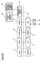
- Fig. 22 is another diagram illustrating hardware structure of the apparatus shown in Fig. 21 using the CPU and peripherals.
- the mouse 2, the keyboard 4, the display 6, the printer 14, the hard disk 20, the memory 24, the flexible disk drive 26 (FDD) and a communication control circuit 154 are connected to the CPU 22.
- both an apparatus 150 for designing circuits and an apparatus 152 for manufacturing of wiring harnesses are connected to the communication control circuit 154 via local area network (hereinafter referred to as LAN) or other communication lines.
- LAN local area network
- connection information being inputted through the apparatus 150 are provided to the CPU 22 via the communication control circuit 154. That is, the communication control circuit 154 forms connection information input means.
- the connection information being stored in the flexible disk can be obtained instead of inputting them through the apparatus 150.
- the FDD 26 forms the connection information input means.
- the connection information can be inputted with the keyboard 4. In such case, the keyboard 4 forms the connection information input means.
- a program(s) for processing the information of wiring harnesses is stored in the hard disk 20. Further, entities of connectors, binding parts and wirings are also stored in the hard disk 20.
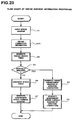
- Fig. 23 is a flow chart showing overall procedures of the program for processing the information of the wiring harnesses.
- a wiring arrangement diagram is inputted in step S1.
- the wiring arrangement diagram is generated by the CPU 22 in accordance with the inputs of the operator through the mouse 2 and the keyboard 4.
- Fig. 24 is a view illustrating the wiring arrangement diagram displayed on the screen.
- the procedures for generating the wiring arrangement diagram are the same as the first embodiment described earlier.
- no connections and none of properties are illustrated in Fig. 24. In this embodiment, no connections and none of properties are necessary.
- the CPU 22 Upon completing the generation of the wiring arrangement diagram, the CPU 22 obtains the connection information (Fig. 23, step S15).
- the connection information are provided by the apparatus 150.
- the apparatus 150 for designing circuits is an apparatus for designing circuits including the connections of connectors, such as CAD apparatus.
- the apparatus 150 for designing circuits may be constituted by the CPU 22 with a CAD program stored in the hard disk 20. In such case, the communication control circuit 154 for 150 is not necessary.
- the CPU 22 outputs a command to the apparatus 150 for sending a connection information table through the communication control circuit 154.
- the apparatus 150 transmits the connection information table shown in Fig. 25 to the CPU 22.
- the connection information table thus transmitted are stored in the hard disk 20 under the control of the CPU 22.
- connection information table shown in Fig. 25 contains data showing connections between the terminals of each connector. In addition, colors and types of electric cables used for the connection and so on are shown in the table. Although, a plurality of columns for inputting lengths of wiring are prepared in the table, no data are inputted therein. It is clearly shown that the first terminal of the connector J101 is connected to the first terminal of the connector J100 on the first line of the connection information table shown in Fig. 25.
- the independent wiring harness diagram is generated in accordance with procedures described hereunder when either of the icon 66 or the icon 68 both for generating the independent wiring harness diagram is clicked with the mouse by the operator (see Fig. 4).
- Data of the wiring arrangement diagram stored in the memory 24 are obtained and stored in the hard disk 20 under the control of the CPU 22. That is, the data shown in Fig. 24 are stored in the hard disk 20.
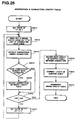
- Fig. 26 is a flow chart showing procedures for generating the wiring length table.
- step S801 a value of "i" is set as 1. Then, the CPU 22 reads out a wiring route listed on "i" th line of the connection information table. In other words, the CPU 22 reads the data indicating the connection between the first terminal of the connector J101 and the first terminal of the connector J100. Then, only the connections between the connectors are extracted from the data thus read out earlier (step S803). In other words, the CPU 22 just extract the data indicating the connection between the connector J101 and the connector J100.
- step S804 a judgement is performed whether or not the data thus extracted have already been extracted. If the data have not been extracted before, the connection between the connectors is recorded on the wiring length table as shown in Fig. 10A (step S805). On the other hand, the step S805 is not performed if the data have already been extracted before.
- step S802 a judgement is performed whether or not the line under processing is the last line of the connection information table.
- the steps followed to the step S802 are performed continuously until the last line by incrementing the value of "i" when the line under processing is not the last line.
- the wiring length table shown in Fig. 10B is generated.
- step S208 On completing the processing until the last line, lengths of the electric cables between all the connectors are obtained from the wiring arrangement diagram (step S208). Corrections of the lengths of the electric cables thus obtained are carried out in accordance with status of the wirings (step S209). Thereafter, rearrangement of the wiring length table is carried out so as to list the connector(s) on upper line of the table in descending order of frequent appearance on the table (step S210). Thus, the wiring length table shown in Fig. 10D is generated.
- the steps performed in step S208 through the step S210 shown in Fig. 26 are the same as the step S208 through the step S210 shown in Fig. 9.
- step S6 generation of both the wiring table (step S6) and the independent wiring harness diagram (step S7) is performed.
- Processing for generating of these are similar to the processing described in Fig. 3.
- the difference between the processing described in Fig. 23 and the processing in Fig. 3 is the way to obtain details of the connections between the terminals.
- the details of the connections are obtained from the properties of the connectors in the flow chart shown in Fig. 3, the details of the connections are obtained from the connection information table in the flow chart shown in Fig. 23.
- the wiring table is generated as a result of generating the wiring length table in accordance with the connection information table in the embodiment described above, the wiring table can be generated by adding the lengths of the electric cables to the connection information table.
- a part of the wiring harness information out of the wiring harness information thus obtained as described above being used in the manufacturing apparatus 152 for manufacturing of wiring harnesses can be transmitted to the manufacturing apparatus 152.
- an icon 69 for transmitting the information shown in Fig. 27 is clicked with the mouse by the operator.
- the CPU 22 controls the communication control circuit 154 so as to transmit parameters need to manufacture the wiring harnesses such as number of terminals of each connector, the lengths of the electric cables between all the connectors. In this way, it is not necessary for the operator to input these parameters all over again. As a result, erroneous inputs of the parameters can be decreased and operating accuracy of apparatus is increased.
- the parameters mentioned above can be outputted to a storing medium so as to be stored therein, and the parameters thus stored in the storing medium can be read by the manufacturing apparatus 152.
- a wiring table illustrating actual sizes of the components can be printed out from the printer 14 in accordance with the wiring arrangement diagram thus inputted.
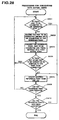
- Fig. 28 is a flow chart of a program for converting the wiring arrangement diagram into actual sizes. Procedures for converting reduced diagram to the actual sizes will be described hereunder when a wiring diagram shown in Fig. 29 is inputted (that is, the arrangement is displayed on the display screen 6).
- step S901 a judgement is carried out whether or not a reference point has a part(s) to be connected thereto after specifying the reference point. In this case, either one of the connector or the binding belt and so on is specified as the reference point. It is assumed that the binding belt "T. 24" is specified as the reference point.
- step S902 the connector "J1" is stored in the memory 24 in a list form. Then, the binding belt “T. 24", the connector "J1" thus stored as the part to be connected and therebetween are converted into their actual size (step S903). In this way, the cursor is moved to a position on the region where the conversion is carried out.
- step S904 a judgement is carried out whether or not other part(s) to be connected to the binding belt "T. 24" (the reference point) is existed in addition to the connector "J1".
- the step S901 is performed if any other the part(s) to be connected is existed.
- the steps S901, S902 and step S903 are sequentially performed because of existence of the binding belt "T. 36" as other part to be connected.
- the binding belt “T. 36" and the wiring being connected between the binding belt “T. 36” and the binding belt “T. 24” are converted into their actual sizes (step S903). In this way, the cursor is moved to a position on the region where the conversion is carried out.
- the binding belt “T. 36” is also added to the list stored in the memory 24.
- step S904 and the step S905 are sequentially performed after completing the conversions with respect to all parts to be connected to the binding belt "T. 24".
- step S905 and step S906 another reference point is specified from the one which has not been specified as the reference point.
- a number "1" is flagged to the part(s) which have been specified as the reference point in the list shown in Fig. 30.
- step S901 The steps followed to the step S901 are performed using far another reference point when unspecified part(s) is listed on the list. In this way, newly specified reference points are recorded on the list, and the conversions are carried out in accordance with the reference points. Thus, the procedures for converting the wiring diagram into actual sizes have been completed when all the parts listed on the list are used as the reference point (step S910).
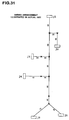
- the wiring diagram being enlarged into the actual sizes shown in Fig. 31 can be generated.
- the wiring diagram thus generated is printed out on a paper by the printer 14.
- Manufacturing process of the wiring harnesses can be carried out easily by pasting (or by directly printing) the wiring diagram shown in Fig. 31 onto a substrate for wiring.
- positions for allocating jigs for wiring can be determined easily and accurately on the actualized wiring diagram shown in Fig. 31 by just disposing the jigs on the arrangement.
- the independent wiring harness diagrams shown in both Figs. 15 and 17 can be actualized to the actual sizes, and the independent wiring harness diagrams thus actualized can be used both for simplifying the manufacturing processes and for allocating jigs of wiring.
- the wiring diagram is not actualized on the display screen of the display 6 for carrying out correction work easily. And the wiring diagram is printed out in the actual sizes for simplifying the manufacturing processes and for allocating jigs.
- the wiring diagram having actual sizes is printed out by the printer 14, the actualized wiring diagram can be displayed on the display 6 as well as outputting that in a data format.
- the wiring harness using the electric cable as the wiring is described in the embodiment described above, the present invention can also be applied to a wiring harness using optical fibers as the wiring.
- the CPU 22 shown in Fig. 1 and Fig. 22 is used for realizing functions described in above embodiments, a part of or all of the functions can be realized by using hardware such as logic circuits or the like.
Abstract
Description
Claims (25)
- An apparatus for processing information of a wiring harness, comprising:entity input means for connectedly arranging entities representing connectors, binding parts and wirings,numeral value input means for relatedly providing length information of the wiring to each entity representing the wiring,means for generating a wiring arrangement diagram in accordance with inputs of the entity input means and the numeral value input means, anddisplay means for displaying the wiring arrangement diagram thus generated,wherein the operator obtains a desired wiring arrangement by using the entity input means and the numeral value input means with referring to the entities and the length information displayed on the display means, andwherein the apparatus further comprises means for generating wiring harness information including a total length of the wiring between each connector in the desired wiring arrangement in accordance with the entities and the length information of the desired wiring arrangement.
- The apparatus in accordance with claim 1, wherein the apparatus further comprises connection input means for inputting connection information between each of the connectors, and
wherein the wiring harness information generating means generates the wiring harness information by additionally considering the connection information inputted with the connection input means. - The apparatus in accordance with claim 2, wherein the connection information inputted with the connection input means is inputted from an apparatus for designing circuits.
- The apparatus in accordance with claim 1, wherein the entity input means is also means for inputting a entity representing a connection between the connectors.
- In an apparatus for processing information of a wiring harness comprising, an input device, a display device, a storing device for storing a program of processing wiring harness information, and a processing device connected to the storing device and performing processing of inputted information through the input device in accordance with the program stored in the storing device,
wherein the program makes the processing device to perform the following steps:connectedly arranging entities representing connectors, binding parts and wirings on the display device in accordance with the inputs inputted through the input device,relatedly providing length information of the wirings to each entity representing the wirings, the length information being inputted through the input device,generating a wiring arrangement diagram in accordance with inputs of the input device,displaying the wiring arrangement diagram thus generated on the display device,inputting a desired wiring arrangement with the input device with referring to the entities and the length information displayed on the display device, andgenerating and outputting wiring harness information including a total length of the wiring between each connector in the desired wiring arrangement in accordance with the entities and the length information of the desired wiring arrangement. - A program storage medium readable by a computer including an input device and a display device, recording a program that make the computer to perform following steps for processing wiring harness information:connectedly arranging entities representing connectors, binding parts and wirings on the display device in accordance with the inputs inputted through the input device,relatedly providing length information of the wiring to each entity representing the wirings, the length information being inputted through the input device,generating a wiring arrangement diagram in accordance with inputs of the input device,displaying the wiring arrangement diagram thus generated on the display device,inputting a desired wiring arrangement with the input device with referring to the entities and the length information displayed on the display device, andgenerating and outputting wiring harness information including a total length of the wiring between each connector in the desired wiring arrangement in accordance with the entities and the length information of the desired wiring arrangement.
- A program storage medium storing the program in accordance with claim 6,
wherein the program makes the machine to input connection information between each of the connectors though the input device, and to generate the wiring harness information by additionally considering the connection information inputted with the input device. - A program storage medium storing the program in accordance with claim 7,
wherein the program makes the computer to perform processing for receiving the connection information through an apparatus for designing circuits and inputting the connection information thus received. - A program storage medium storing the program in accordance with claim 6,
wherein the program makes the computer to input entity representing a connection between connectors through the input device, and to perform processing for connectedly arranging entity representing the connectors, binding parts and wirings on the display device. - A program storage medium storing any one of the programs in accordance with claims 6 through 9,
wherein the program makes the computer to perform processing for generating the wiring harness information in order to output a wiring diagram illustrating actual length of the wiring in accordance with the entities and the length information. - A program storage medium storing the program in accordance with claim 10,
wherein the program makes the computer to display the wiring arrangement diagram not illustrating actual length of the wiring on the display device, and to output the wiring diagram illustrating actual length of the wiring from a printing device. - A program storage medium storing any one of the programs in accordance with claims 6 through 9,
wherein the program makes the computer to perform processing for generating wiring harness information of an independent wiring harness being connected each other as a group in accordance with the entities and the length information. - A program storage medium storing the program in accordance with claim 12,wherein the program makes the computer to input the connection information of each terminal between each of the connectors correspondingly with the entity representing connectors, binding parts and wirings,and to perform processing for generating the wiring harness information of the independent wiring harness including the connection information of each terminal between each connector by additionally considering the connection information of each terminal between each of the connectors thus inputted.
- A program storage medium storing any one of the programs in accordance with claims 6 through 9,
wherein the program makes the computer to perform a judgement whether or not connection status of wiring in the independent wiring harness being extracted comply with a predetermined rule. - A program storage medium storing any one of the programs in accordance with claims 6 through 9,
wherein the program makes the computer to perform correction of a given length of the wiring by considering length of displacement in actual wiring work as correction value. - A program storage medium storing the program in accordance with claim 15,
wherein the correction value at least includes a length caused by displacement of the wiring work or a margin for crimping the connector terminals. - A program storage medium storing any one of the programs in accordance with claims 6 through 9, wherein the program makes the computer to perform processing for providing a part of the wiring harness information to a wiring harness manufacturing device, the part of the wiring harness information being used in the wiring harness manufacturing device.
- A method of generating a wiring harness diagram comprising the steps of:displaying connector and binding part on a display screen and connecting therebetween with wiring as well as providing connection information between each connector,providing a length of the wiring connecting the connectors and the binding parts,outputting an independent wiring harness diagram being connected each other as a group in accordance with the connection information.
- A method of manufacturing a substrate for wiring, comprising the steps of:preparing the substrate,directly drawing a wiring diagram in actual size on the substrate, or fixing a sheet illustrating the wiring diagram in actual size on the substrate,disposing a supporting member for wiring at least a position of locating a binding part in the wiring diagram.
- A method for manufacturing a wiring harness using a computer having an input device and a display device, comprising steps of:inputting entities representing connectors, binding parts, wirings length information of the wirings from the input device,inputting a desired wiring arrangement from the input device with referring to a wiring arrangement diagram generated in basis of the entities and the length information and displayed on the display device, andmaking the wiring harness using information including a total length of the wiring between each connectors, the harness information being generated in basis of the entities and the length information of the desired wiring arrangement.
- A method for manufacturing a wiring harness in accordance with claim 20,
wherein the wiring harness information is generated by additionally considering a connection information inputted from an apparatus for designing circuits. - A wiring harness manufactured by a computer having an input device and a display device,
wherein the wiring harness being manufactured by using wiring harness information, the wiring harness information being generated by a method comprising steps of:inputting entities representing connectors, binding parts, wirings length information of the wirings from the input device,inputting a desired wiring arrangement from the input device with referring to a wiring arrangement diagram generated in basis of the entities and the length information and displayed on the display device, andmaking the wiring harness using information including a total length of the wiring between each connectors, the harness information being generated in basis of the entities and the length information of the desired wiring arrangement. - A wiring harness in accordance with claim 22,
wherein the wiring harness information is generated by additionally considering a connection information inputted from an apparatus for designing circuits. - A method of manufacturing harness wired electrical equipment having connectors and a wiring harness connected to said connectors, comprising steps of:providing said electrical equipment in a state that it is to be wired by said wiring harness; andconnecting said connectors of said electrical equipment by said wiring harness by manufacturing said wiring harness in accordance with the method of claim 20 and connecting said wiring harness to said connectors.
- An apparatus for processing information of a wiring harness, comprising:entity input means for connectedly arranging entities representing connectors, binding parts and wirings;numeral value input means for relatedly providing length information of the wiring to each entity representing the wiring;means for generating a wiring arrangement diagram in accordance with inputs of the entity input means and the numeral value input means;display means for displaying the wiring arrangement diagram thus generated; andmeans for generating wiring harness information including a total length of the wiring between each connector in the desired wiring arrangement in accordance with the entities and the length information of the desired wiring arrangement input via said entity input means and said numeral value input means, respectively.
Applications Claiming Priority (3)
| Application Number | Priority Date | Filing Date | Title |
|---|---|---|---|
| JP181138/97 | 1997-07-07 | ||
| JP18113897 | 1997-07-07 | ||
| JP18113897 | 1997-07-07 |
Publications (3)
| Publication Number | Publication Date |
|---|---|
| EP0891021A2 true EP0891021A2 (en) | 1999-01-13 |
| EP0891021A3 EP0891021A3 (en) | 1999-12-01 |
| EP0891021B1 EP0891021B1 (en) | 2005-11-23 |
Family
ID=16095560
Family Applications (1)
| Application Number | Title | Priority Date | Filing Date |
|---|---|---|---|
| EP98305408A Expired - Lifetime EP0891021B1 (en) | 1997-07-07 | 1998-07-07 | An apparatus for processing information of a wiring harness |
Country Status (4)
| Country | Link |
|---|---|
| US (2) | US6438435B1 (en) |
| EP (1) | EP0891021B1 (en) |
| DE (1) | DE69832441D1 (en) |
| HK (1) | HK1017951A1 (en) |
Cited By (4)
| Publication number | Priority date | Publication date | Assignee | Title |
|---|---|---|---|---|
| EP1205862A3 (en) * | 2000-10-19 | 2003-09-03 | General Electric Company | Methods and apparatus for electronically modeling aircraft engine harnesses |
| SG118128A1 (en) * | 2001-04-30 | 2006-01-27 | Gen Electric | Method and system for constructing technical plans |
| WO2007121729A2 (en) | 2006-04-21 | 2007-11-01 | Steinhauer Elektromaschinen Ag | Method for wiring a switchgear assembly, wiring station |
| DE102019125727A1 (en) * | 2019-09-25 | 2021-03-25 | Deutsches Zentrum für Luft- und Raumfahrt e.V. | Method and device for verifying connected colored cables |
Families Citing this family (19)
| Publication number | Priority date | Publication date | Assignee | Title |
|---|---|---|---|---|
| US6438435B1 (en) * | 1997-07-07 | 2002-08-20 | J.S.T. Mfg. Co. Ltd. | Apparatus for processing information of a wiring harness |
| US6564112B1 (en) * | 1999-11-08 | 2003-05-13 | Eventide Inc. | Method of customizing electronic systems based on user specifications |
| JP2002056040A (en) * | 2000-08-14 | 2002-02-20 | Nec Corp | Method for designing cable clamp and cable shapes by three-dimensional cad and computer-readable recording medium |
| US7107197B1 (en) * | 2001-01-26 | 2006-09-12 | Mentor Graphics Corporation | Wiring harness data systems |
| JP2003022721A (en) * | 2001-07-09 | 2003-01-24 | Sumitomo Wiring Syst Ltd | Assisting method and program for designing wire harness |
| US7437688B2 (en) * | 2001-12-27 | 2008-10-14 | Caterpillar Inc. | Element routing method and apparatus |
| EP1366959B1 (en) * | 2002-05-22 | 2009-07-15 | Yazaki Corporation | Wire harness design support system |
| US7082590B2 (en) * | 2003-10-23 | 2006-07-25 | The Boeing Company | Three-dimensional wire harness assembly models from three-dimensional zone models |
| JP5674097B2 (en) | 2009-12-04 | 2015-02-25 | 矢崎総業株式会社 | Wire harness continuity inspection apparatus, wire harness continuity inspection program, and wire harness continuity inspection method |
| US8347242B2 (en) * | 2010-01-05 | 2013-01-01 | The Boeing Company | Processing wiring diagrams in a data processing system |
| JP5674098B2 (en) | 2010-02-08 | 2015-02-25 | 矢崎総業株式会社 | Wire harness continuity inspection apparatus, wire harness continuity inspection program, and wire harness continuity inspection method |
| US8862722B2 (en) * | 2010-03-31 | 2014-10-14 | Verizon Patent And Licensing Inc. | Method and system for providing monitoring of network environment changes |
| JP5586325B2 (en) | 2010-05-28 | 2014-09-10 | 矢崎総業株式会社 | Wire harness continuity inspection method and wire harness continuity inspection program |
| US9257808B1 (en) | 2010-09-10 | 2016-02-09 | Automated Wiring Systems, LLC | Integrated wire harness batch production with double buffer assembly systems and methods |
| US8442664B1 (en) | 2010-09-10 | 2013-05-14 | Enovation Controls, Inc. | Integrated wire harness batch production systems and methods |
| FR2973903B1 (en) * | 2011-04-05 | 2013-04-05 | Bull Sas | METHOD AND DEVICE FOR MANAGING WIRING IN A CLUSTER |
| US8719758B1 (en) * | 2011-09-23 | 2014-05-06 | Custom Virtual Environments, Inc. | Methods and apparatus for automated wiring diagram generation |
| US10402504B1 (en) | 2013-12-10 | 2019-09-03 | Enovation Controls, Llc | Time-saving and error-minimizing multiscopic hydraulic system design canvas |
| JP6020777B1 (en) * | 2016-03-01 | 2016-11-02 | 日立金属株式会社 | Wire harness wiring work program |
Citations (3)
| Publication number | Priority date | Publication date | Assignee | Title |
|---|---|---|---|---|
| EP0304866A2 (en) * | 1987-08-24 | 1989-03-01 | International Business Machines Corporation | System for ensuring device compatibility |
| EP0424189A1 (en) * | 1989-09-21 | 1991-04-24 | AEROSPATIALE Société Nationale Industrielle | Computer system for reconstructing the diagram of at least one part of the electrical wiring of an installation |
| US5506950A (en) * | 1992-12-18 | 1996-04-09 | Computervision Corporation | Method and apparatus for producing a three dimensional representation of a wire harness into a two dimensional presentation |
Family Cites Families (18)
| Publication number | Priority date | Publication date | Assignee | Title |
|---|---|---|---|---|
| US3946768A (en) * | 1972-07-25 | 1976-03-30 | Thomas & Betts Corporation | Wire harness board |
| JPS62166700A (en) | 1986-01-20 | 1987-07-23 | Matsushita Electric Ind Co Ltd | Speaker unit |
| JPH0793060B2 (en) | 1986-08-29 | 1995-10-09 | 株式会社日立製作所 | Automatic wiring device |
| JPS63140373A (en) * | 1986-12-02 | 1988-06-11 | Oki Electric Ind Co Ltd | Sheet metal developing method in cad/cam device |
| US5033188A (en) * | 1988-10-18 | 1991-07-23 | Amp Incorporated | Method of making an electrical harness |
| FR2642931B1 (en) * | 1989-02-07 | 1996-01-19 | Aerospatiale Ste Nat Indle | SYSTEM FOR THE REALIZATION IN A PLANE OF A WIRING PART |
| US5067379A (en) * | 1989-03-20 | 1991-11-26 | Mechtrix Corporation | Electronic display system for wire stripping machine |
| FR2648667B1 (en) * | 1989-06-15 | 1991-09-27 | Aerospatiale | METHOD AND DEVICE FOR PRODUCING WIRING COMPONENTS |
| US5109479A (en) * | 1989-09-07 | 1992-04-28 | Amp-Akzo Corporation | Method of designing three dimensional electrical circuits |
| US5050093A (en) * | 1989-10-19 | 1991-09-17 | The Boeing Company | Method and apparatus for inspecting electrical wire |
| US5140873A (en) * | 1991-07-02 | 1992-08-25 | Wiretech Co. | Wire stripper |
| JP2808976B2 (en) * | 1992-03-02 | 1998-10-08 | 住友電装株式会社 | Harness manufacturing apparatus and harness manufacturing method |
| JP2855961B2 (en) * | 1992-04-21 | 1999-02-10 | 住友電装株式会社 | Inspection method of wire harness temporary binding circuit and its inspection device |
| JP2842175B2 (en) * | 1993-11-01 | 1998-12-24 | 住友電装株式会社 | Wire measurement cutting device and wire replacement method |
| JP2897648B2 (en) | 1994-08-30 | 1999-05-31 | 住友電装株式会社 | Equipment for manufacturing electric wires with terminals |
| US5864482A (en) * | 1996-05-06 | 1999-01-26 | Amadasoft America, Inc. | Apparatus and method for managing distributing design and manufacturing information throughout a sheet metal production facility |
| US6438435B1 (en) * | 1997-07-07 | 2002-08-20 | J.S.T. Mfg. Co. Ltd. | Apparatus for processing information of a wiring harness |
| JP3672215B2 (en) | 1998-03-16 | 2005-07-20 | 矢崎総業株式会社 | Wire harness manufacturing system |
-
1998
- 1998-07-07 US US09/111,191 patent/US6438435B1/en not_active Expired - Lifetime
- 1998-07-07 EP EP98305408A patent/EP0891021B1/en not_active Expired - Lifetime
- 1998-07-07 DE DE69832441T patent/DE69832441D1/en not_active Expired - Lifetime
-
1999
- 1999-07-13 HK HK99102996A patent/HK1017951A1/en not_active IP Right Cessation
-
2002
- 2002-04-02 US US10/115,468 patent/US6694203B2/en not_active Expired - Lifetime
Patent Citations (3)
| Publication number | Priority date | Publication date | Assignee | Title |
|---|---|---|---|---|
| EP0304866A2 (en) * | 1987-08-24 | 1989-03-01 | International Business Machines Corporation | System for ensuring device compatibility |
| EP0424189A1 (en) * | 1989-09-21 | 1991-04-24 | AEROSPATIALE Société Nationale Industrielle | Computer system for reconstructing the diagram of at least one part of the electrical wiring of an installation |
| US5506950A (en) * | 1992-12-18 | 1996-04-09 | Computervision Corporation | Method and apparatus for producing a three dimensional representation of a wire harness into a two dimensional presentation |
Cited By (6)
| Publication number | Priority date | Publication date | Assignee | Title |
|---|---|---|---|---|
| EP1205862A3 (en) * | 2000-10-19 | 2003-09-03 | General Electric Company | Methods and apparatus for electronically modeling aircraft engine harnesses |
| US7024341B2 (en) | 2000-10-19 | 2006-04-04 | General Electric Company | Methods and apparatus for electronically modeling aircraft engine harnesses |
| SG118128A1 (en) * | 2001-04-30 | 2006-01-27 | Gen Electric | Method and system for constructing technical plans |
| WO2007121729A2 (en) | 2006-04-21 | 2007-11-01 | Steinhauer Elektromaschinen Ag | Method for wiring a switchgear assembly, wiring station |
| WO2007121729A3 (en) * | 2006-04-21 | 2008-02-28 | Steinhauer Elmasch Ag | Method for wiring a switchgear assembly, wiring station |
| DE102019125727A1 (en) * | 2019-09-25 | 2021-03-25 | Deutsches Zentrum für Luft- und Raumfahrt e.V. | Method and device for verifying connected colored cables |
Also Published As
| Publication number | Publication date |
|---|---|
| EP0891021B1 (en) | 2005-11-23 |
| EP0891021A3 (en) | 1999-12-01 |
| DE69832441D1 (en) | 2005-12-29 |
| US6694203B2 (en) | 2004-02-17 |
| US20020165632A1 (en) | 2002-11-07 |
| US6438435B1 (en) | 2002-08-20 |
| HK1017951A1 (en) | 1999-12-03 |
Similar Documents
| Publication | Publication Date | Title |
|---|---|---|
| EP0891021B1 (en) | An apparatus for processing information of a wiring harness | |
| EP0304865B1 (en) | System for designing intercommunication networks | |
| EP0304866B1 (en) | System for ensuring device compatibility | |
| EP3477513B1 (en) | Designing support method and designing support system | |
| US4985855A (en) | Method for producing installation instructions for three dimensional assemblies | |
| JPH01131963A (en) | Automatic generating system for configuration connecting constitution | |
| EP0304864A2 (en) | Method for producing building instructions for three dimensional assemblies | |
| JPH0728859A (en) | Editor system for logic circuit diagram | |
| US6205573B1 (en) | Delay analysis result display device | |
| US7340683B2 (en) | Programming tool | |
| WO2008044699A1 (en) | Designing support method, designing support apparatus, program, and computer-readable storage medium | |
| JP2982796B2 (en) | Harness information processor | |
| JP4050493B2 (en) | Wire harness design equipment | |
| US6075529A (en) | GUI automatic generating system for inputting data of a manufacturing process | |
| CN102667652B (en) | Field device having a display unit and method for operating said display unit | |
| JPH0785099A (en) | System for displaying hierarchy | |
| US5923336A (en) | Method of associating a dimensional representation with a structure in a CAD system | |
| JP4752735B2 (en) | Printing device | |
| JP7392992B2 (en) | Estimation device, estimation method, and computer program | |
| JP2005316947A (en) | Information display control apparatus, server and program | |
| JP3212207B2 (en) | Connection CAD system | |
| JP2024027343A (en) | Design change confirmation method, program, and design change confirmation device | |
| US20110007083A1 (en) | Distributed processing system, information processing apparatus, and distributed processing method | |
| JPH11219381A (en) | Device and method for drawing connection diagram and recording medium | |
| JPH08194723A (en) | Electric parts classification support device and its method |
Legal Events
| Date | Code | Title | Description |
|---|---|---|---|
| PUAI | Public reference made under article 153(3) epc to a published international application that has entered the european phase |
Free format text: ORIGINAL CODE: 0009012 |
|
| AK | Designated contracting states |
Kind code of ref document: A2 Designated state(s): BE DE FR GB IT NL SE |
|
| AX | Request for extension of the european patent |
Free format text: AL;LT;LV;MK;RO;SI |
|
| PUAL | Search report despatched |
Free format text: ORIGINAL CODE: 0009013 |
|
| AK | Designated contracting states |
Kind code of ref document: A3 Designated state(s): AT BE CH CY DE DK ES FI FR GB GR IE IT LI LU MC NL PT SE |
|
| AX | Request for extension of the european patent |
Free format text: AL;LT;LV;MK;RO;SI |
|
| RIC1 | Information provided on ipc code assigned before grant |
Free format text: 6H 01R 43/28 A, 6G 06F 17/50 B |
|
| 17P | Request for examination filed |
Effective date: 19991119 |
|
| AKX | Designation fees paid |
Free format text: BE DE FR GB IT NL SE |
|
| 17Q | First examination report despatched |
Effective date: 20021204 |
|
| GRAP | Despatch of communication of intention to grant a patent |
Free format text: ORIGINAL CODE: EPIDOSNIGR1 |
|
| GRAS | Grant fee paid |
Free format text: ORIGINAL CODE: EPIDOSNIGR3 |
|
| GRAA | (expected) grant |
Free format text: ORIGINAL CODE: 0009210 |
|
| AK | Designated contracting states |
Kind code of ref document: B1 Designated state(s): BE DE FR GB IT NL SE |
|
| PG25 | Lapsed in a contracting state [announced via postgrant information from national office to epo] |
Ref country code: NL Free format text: LAPSE BECAUSE OF FAILURE TO SUBMIT A TRANSLATION OF THE DESCRIPTION OR TO PAY THE FEE WITHIN THE PRESCRIBED TIME-LIMIT Effective date: 20051123 Ref country code: IT Free format text: LAPSE BECAUSE OF FAILURE TO SUBMIT A TRANSLATION OF THE DESCRIPTION OR TO PAY THE FEE WITHIN THE PRE;WARNING: LAPSES OF ITALIAN PATENTS WITH EFFECTIVE DATE BEFORE 2007 MAY HAVE OCCURRED AT ANY TIME BEFORE 2007. THE CORRECT EFFECTIVE DATE MAY BE DIFFERENT FROM THE ONE RECORDED.SCRIBED TIME-LIMIT Effective date: 20051123 Ref country code: BE Free format text: LAPSE BECAUSE OF FAILURE TO SUBMIT A TRANSLATION OF THE DESCRIPTION OR TO PAY THE FEE WITHIN THE PRESCRIBED TIME-LIMIT Effective date: 20051123 |
|
| REG | Reference to a national code |
Ref country code: GB Ref legal event code: FG4D |
|
| REF | Corresponds to: |
Ref document number: 69832441 Country of ref document: DE Date of ref document: 20051229 Kind code of ref document: P |
|
| REG | Reference to a national code |
Ref country code: HK Ref legal event code: GR Ref document number: 1017951 Country of ref document: HK |
|
| PG25 | Lapsed in a contracting state [announced via postgrant information from national office to epo] |
Ref country code: SE Free format text: LAPSE BECAUSE OF FAILURE TO SUBMIT A TRANSLATION OF THE DESCRIPTION OR TO PAY THE FEE WITHIN THE PRESCRIBED TIME-LIMIT Effective date: 20060223 |
|
| PG25 | Lapsed in a contracting state [announced via postgrant information from national office to epo] |
Ref country code: DE Free format text: LAPSE BECAUSE OF FAILURE TO SUBMIT A TRANSLATION OF THE DESCRIPTION OR TO PAY THE FEE WITHIN THE PRESCRIBED TIME-LIMIT Effective date: 20060224 |
|
| NLV1 | Nl: lapsed or annulled due to failure to fulfill the requirements of art. 29p and 29m of the patents act | ||
| PLBE | No opposition filed within time limit |
Free format text: ORIGINAL CODE: 0009261 |
|
| STAA | Information on the status of an ep patent application or granted ep patent |
Free format text: STATUS: NO OPPOSITION FILED WITHIN TIME LIMIT |
|
| PG25 | Lapsed in a contracting state [announced via postgrant information from national office to epo] |
Ref country code: FR Free format text: LAPSE BECAUSE OF FAILURE TO SUBMIT A TRANSLATION OF THE DESCRIPTION OR TO PAY THE FEE WITHIN THE PRESCRIBED TIME-LIMIT Effective date: 20061020 |
|
| 26N | No opposition filed |
Effective date: 20060824 |
|
| EN | Fr: translation not filed | ||
| PG25 | Lapsed in a contracting state [announced via postgrant information from national office to epo] |
Ref country code: FR Free format text: LAPSE BECAUSE OF FAILURE TO SUBMIT A TRANSLATION OF THE DESCRIPTION OR TO PAY THE FEE WITHIN THE PRESCRIBED TIME-LIMIT Effective date: 20051123 |
|
| PGFP | Annual fee paid to national office [announced via postgrant information from national office to epo] |
Ref country code: GB Payment date: 20170719 Year of fee payment: 20 |
|
| REG | Reference to a national code |
Ref country code: GB Ref legal event code: PE20 Expiry date: 20180706 |
|
| PG25 | Lapsed in a contracting state [announced via postgrant information from national office to epo] |
Ref country code: GB Free format text: LAPSE BECAUSE OF EXPIRATION OF PROTECTION Effective date: 20180706 |