EP0890128B1 - Polarized illumination system for lcd projector - Google Patents
Polarized illumination system for lcd projector Download PDFInfo
- Publication number
- EP0890128B1 EP0890128B1 EP97919891A EP97919891A EP0890128B1 EP 0890128 B1 EP0890128 B1 EP 0890128B1 EP 97919891 A EP97919891 A EP 97919891A EP 97919891 A EP97919891 A EP 97919891A EP 0890128 B1 EP0890128 B1 EP 0890128B1
- Authority
- EP
- European Patent Office
- Prior art keywords
- microprismatic
- light
- beams
- exit
- reflectorized
- Prior art date
- Legal status (The legal status is an assumption and is not a legal conclusion. Google has not performed a legal analysis and makes no representation as to the accuracy of the status listed.)
- Expired - Lifetime
Links
Images


Classifications
-
- G—PHYSICS
- G02—OPTICS
- G02B—OPTICAL ELEMENTS, SYSTEMS OR APPARATUS
- G02B27/00—Optical systems or apparatus not provided for by any of the groups G02B1/00 - G02B26/00, G02B30/00
- G02B27/28—Optical systems or apparatus not provided for by any of the groups G02B1/00 - G02B26/00, G02B30/00 for polarising
- G02B27/283—Optical systems or apparatus not provided for by any of the groups G02B1/00 - G02B26/00, G02B30/00 for polarising used for beam splitting or combining
-
- G—PHYSICS
- G02—OPTICS
- G02B—OPTICAL ELEMENTS, SYSTEMS OR APPARATUS
- G02B27/00—Optical systems or apparatus not provided for by any of the groups G02B1/00 - G02B26/00, G02B30/00
- G02B27/28—Optical systems or apparatus not provided for by any of the groups G02B1/00 - G02B26/00, G02B30/00 for polarising
-
- G—PHYSICS
- G02—OPTICS
- G02F—OPTICAL DEVICES OR ARRANGEMENTS FOR THE CONTROL OF LIGHT BY MODIFICATION OF THE OPTICAL PROPERTIES OF THE MEDIA OF THE ELEMENTS INVOLVED THEREIN; NON-LINEAR OPTICS; FREQUENCY-CHANGING OF LIGHT; OPTICAL LOGIC ELEMENTS; OPTICAL ANALOGUE/DIGITAL CONVERTERS
- G02F1/00—Devices or arrangements for the control of the intensity, colour, phase, polarisation or direction of light arriving from an independent light source, e.g. switching, gating or modulating; Non-linear optics
- G02F1/01—Devices or arrangements for the control of the intensity, colour, phase, polarisation or direction of light arriving from an independent light source, e.g. switching, gating or modulating; Non-linear optics for the control of the intensity, phase, polarisation or colour
- G02F1/13—Devices or arrangements for the control of the intensity, colour, phase, polarisation or direction of light arriving from an independent light source, e.g. switching, gating or modulating; Non-linear optics for the control of the intensity, phase, polarisation or colour based on liquid crystals, e.g. single liquid crystal display cells
- G02F1/133—Constructional arrangements; Operation of liquid crystal cells; Circuit arrangements
- G02F1/1333—Constructional arrangements; Manufacturing methods
- G02F1/1335—Structural association of cells with optical devices, e.g. polarisers or reflectors
- G02F1/133528—Polarisers
- G02F1/133536—Reflective polarizers
-
- G—PHYSICS
- G02—OPTICS
- G02F—OPTICAL DEVICES OR ARRANGEMENTS FOR THE CONTROL OF LIGHT BY MODIFICATION OF THE OPTICAL PROPERTIES OF THE MEDIA OF THE ELEMENTS INVOLVED THEREIN; NON-LINEAR OPTICS; FREQUENCY-CHANGING OF LIGHT; OPTICAL LOGIC ELEMENTS; OPTICAL ANALOGUE/DIGITAL CONVERTERS
- G02F1/00—Devices or arrangements for the control of the intensity, colour, phase, polarisation or direction of light arriving from an independent light source, e.g. switching, gating or modulating; Non-linear optics
- G02F1/01—Devices or arrangements for the control of the intensity, colour, phase, polarisation or direction of light arriving from an independent light source, e.g. switching, gating or modulating; Non-linear optics for the control of the intensity, phase, polarisation or colour
- G02F1/13—Devices or arrangements for the control of the intensity, colour, phase, polarisation or direction of light arriving from an independent light source, e.g. switching, gating or modulating; Non-linear optics for the control of the intensity, phase, polarisation or colour based on liquid crystals, e.g. single liquid crystal display cells
- G02F1/133—Constructional arrangements; Operation of liquid crystal cells; Circuit arrangements
- G02F1/1333—Constructional arrangements; Manufacturing methods
- G02F1/1335—Structural association of cells with optical devices, e.g. polarisers or reflectors
- G02F1/133528—Polarisers
- G02F1/13355—Polarising beam splitters [PBS]
-
- G—PHYSICS
- G02—OPTICS
- G02F—OPTICAL DEVICES OR ARRANGEMENTS FOR THE CONTROL OF LIGHT BY MODIFICATION OF THE OPTICAL PROPERTIES OF THE MEDIA OF THE ELEMENTS INVOLVED THEREIN; NON-LINEAR OPTICS; FREQUENCY-CHANGING OF LIGHT; OPTICAL LOGIC ELEMENTS; OPTICAL ANALOGUE/DIGITAL CONVERTERS
- G02F1/00—Devices or arrangements for the control of the intensity, colour, phase, polarisation or direction of light arriving from an independent light source, e.g. switching, gating or modulating; Non-linear optics
- G02F1/01—Devices or arrangements for the control of the intensity, colour, phase, polarisation or direction of light arriving from an independent light source, e.g. switching, gating or modulating; Non-linear optics for the control of the intensity, phase, polarisation or colour
- G02F1/13—Devices or arrangements for the control of the intensity, colour, phase, polarisation or direction of light arriving from an independent light source, e.g. switching, gating or modulating; Non-linear optics for the control of the intensity, phase, polarisation or colour based on liquid crystals, e.g. single liquid crystal display cells
- G02F1/133—Constructional arrangements; Operation of liquid crystal cells; Circuit arrangements
- G02F1/1333—Constructional arrangements; Manufacturing methods
- G02F1/1335—Structural association of cells with optical devices, e.g. polarisers or reflectors
- G02F1/1336—Illuminating devices
- G02F1/13362—Illuminating devices providing polarized light, e.g. by converting a polarisation component into another one
Definitions
- the present invention generally relates to optical illumination systems, and more particularly to a polarized illumination system having a novel spatial integrator, including variations for controlling aspect ratio, the system being suited for use with electronic projection displays, particularly of the liquid crystal display type.
- Polarized light has been traditionally produced by an absorbing polarizer or a polarizing beam splitter (PBS) cube.
- PBS polarizing beam splitter
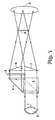
- Japanese Patent Application (Kokai) No. 61-122626 describes a polarizing illumination device, that spatially integrates the separated beams at the LCD plane by means of a pair of wedge prisms.
- the device uses a light source 1, collimator 2, PBS cube 3, right angle prism 4, half-wave retarder 5 , wedge prisms 6 and 7 , LCD panel 8 , and projection lens 9 .
- the wedge prisms There must be a considerable distance between the wedge prisms and the LCD, since the beams are converging, and the incidence angle on the LCD must be kept small, which unduly restricts use of the device.
- U.S. Patent Nos. 4,913,529 and 4,969,730 describe converting polarized light projection illumination systems using polarizing plates or a PBS cube, combining the separated beams at the LCD with steering prisms.
- U.S. Patent No. 5,381,278 uses converging and diverging lenses to redirect the separated beams to the LCD panel.
- Japanese Patent Application (Kokai) No. 71-99185 uses dual polarizing beam splitters, achieving a beam of oblong cross-section, but with no spatial recombination of the separate beams.
- European Patent Application No. 615,148 achieves polarization conversion and spatial recombination by recycling light backwards to the light source reflector, as does European Patent Application No.
- U.S. Patent No. 5,181,054 achieves spatial recombination of the separated beams by sending the beams through the LCD in opposite directions, as does U.S. Patent No. 5,428,469 (also assigned to 3M).
- U.S. Patent No. 5,446,510 achieves a common collimation angle for the separate beams, but without any spatial integration.
- U.S. Patent Nos. 5,042,921 and 5,124,841 describe polarization converters with spatial integration achieved by refracting microprisms.
- the polarization converter described in European Patent Application No. 463,500 preserves the aspect ratio of the original beam, but requires the use of two LCD's, and European Patent Application No. 456,427 matches the beam size to the LCD panel by the use of back reflections from a lamp reflector having a rectangular exit aperture.
- the efficiency of these systems is limited by the complexity of the optics, quality of the reflectance coatings, degree of spatial recombination and beam shaping, and high chromatic dispersion of the refracting elements.
- US 5 359 455 describes a polarization forming optical device comprising a light source, a polarization beam splitter, a half-wave plate, two mirrors and two prism formed plates.
- the light beam from the light source is split in two light beams by means of the beam splitter.
- One of the two light beams is rotated at 90° on the half-wave plate.
- the two beams are separately reflected by the two mirrors to the prism formed plate.
- the two beams are bent by the prism formed plate and thereafter partially reflected from the mirror to the second prism formed plate which is again bending the light beams.
- Spatial integration of the separate beams is important since the separated beams usually differ in intensity and color temperature. Collimation of the beam incident on the LCD is important, since most displays of this type work best with a common and low incidence angle of the illuminating light. Also, collimated light can be more efficiently focused by a field lens to the projection lens. Beam shaping is important to transmit maximum light through the rectangular aperture of the LCD. Lastly, compactness is desirable to reduce the size of the projector unit. None of the foregoing systems provides optimum performance in all of these areas.
- the present invention provides a polarized illumination system particularly suited for an LCD projector, the system generally comprising a light source, means for collimating light from the source into an entrance beam, means for separating the entrance beam into a first beam having a first polarization state, and a second beam having a second polarization state, retarder means for converting said first beam from said first polarization state to said second polarization state, means for spatially integrating said first and second beams to create a collimated, exit beam having an aspect ratio, and means for changing the aspect ratio of said exit beam.
- the integrating means preferably comprises a spatial integrator cell having a first microprismatic element with a planar surface and a surface of prismatic grooves opposite said planar surface, and a second microprismatic element with another planar surface and another surface of prismatic grooves opposite the other planar surface and facing said surface of prismatic grooves on said first microprismatic element, there further being first and second, generally opposed reflecting surfaces adjacent first and second sides, respectively, of the second microprismatic element.
- the means for separating the light may comprise a polarizing beam splitter (PBS) which creates the first and second beams, and the PBS may be adapted to direct the first and second beams to first and second reflectorized wedge prisms, respectively.
- the spatial integrator cell has an exit element which is combined with a first beam compression element, and a second beam compression element is positioned adjacent the first beam compression element to achieve the changed aspect ratio.
- the first beam compression element may be a positive cylinder Fresnel lens, and the second beam compression element a negative cylinder lens:
- the first beam compression element may be a first microprismatic element, and the second beam compression element a second microprismatic element positioned at an oblique angle with respect to the first microprismatic element.
- the means for changing the aspect ratio of the exit beam may further be designed to additionally cause the exit beam to deviate by approximately 90°.
- the current invention avoids many of the deficiencies of the prior art, by producing a converted secondary beam of collimated polarized light, and spatially recombining this beam with the primary beam using total internally reflective linear microprisms, preserving the polarization and collimation with minimal chromatic dispersion.
- the aspect ratio of the spatially integrated beam is then efficiently converted to match the format of an LCD panel. There is no requirement for any back-reflection or recycling of the beam in the direction of the light source, and the single collimated beam passing through the LCD panel can be more efficiently focused to the projection lens.
- System 10 is particularly adapted for use with a liquid crystal display (LCD) projector, and the combination generally comprises a light source or lamp 12, a collimator or parabolic reflector 14, means 16 for separating p- and s-polarized light, taking the form of a polarizing beam splitter (PBS), mean 18 for redirecting one of the polarized beams (in this case, the reflected beam) parallel with the other polarized beam (the transmitted beam), taking the form of a right angle prism reflector, a half-wave retarder plate 20, a spatial integrator cell 22, an analyzer 24, an LCD panel 26, and a projection lens 28.
- Embodiment 10 is a single-panel, transmissive LCD projector, but those skilled in the art will appreciate that the general principle can be extended to color and pseudo-color transmissive LCD projectors using multiple panels, as well as reflective LCD light valve projectors.
- Randomly polarized light from light source 12 is collimated by parabolic reflector 14 (or some other means) and enters PBS cube 16 .
- the p-polarized light is transmitted and the reflected s-polarized light is turned 90° by right angle reflecting prism 18, where it is then converted to p-polarized light by half-wave ( ⁇ /2) retarder plate 20.
- the adjacent and spatially separated collimated light beams enter the microprismatic spatial integrator cell 22 where they are spatially integrated and exit as a single collimated polarized beam.
- Components 12-18 are individually known in the prior art and nearly any conventional components will suffice. Therefore, in embodiment 10 , the primary novelty resides in spatial integrator 22 .
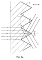
- FIG. 3 shows spatial integrator cell 22.
- Each adjacent entrance beam is equally deviated by the first microprismatic element 32, which consists of a series of 60° equilateral linear microprisms 34 (see Figure 3a).
- Half of the light passes directly to a second, oppositely disposed microprismatic element 36 .
- the other half of the light is reflected off side mirrors 38 and 40, where it then passes to the opposite microprismatic element 36.
- both beams exit the cell as a spatially integrated and collimated beam.
- the spatial integrator cell length L A tan( ⁇ /6), where A is the half-height of the cell (see Figure 2), and light rays entering the center of cell 22 exit at the edge of the cell.
- TIR total internal reflection
- One standard method of aspect ratio conversion that preserves the direction of the light beam is by the use of positive and negative cylinder lenses 42 and 44, respectively, as shown in Figure 4.
- a novel variation of this method is used in the current invention by forming a positive cylinder Fresnel lens 46 in the exit surface of the spatial integrator cell 48, as shown if Figure 5.
- the negative cylinder lens 50 can be continuous or of the Fresnel type.
- Another standard method of converting aspect ratio, or anamorphic beam compression uses a pair of identical prisms as shown in Figure 6.
- the chromatic dispersion of the first prism 52 is canceled by the opposite dispersion of the second prism 54, and the direction of the collimated light is preserved.
- a similar effect may be achieved in the current invention by forming the first element as a series of linear microprisms on the exit element 56 of a spatial integrator cell 58.
- a second linear microprismatic element 60 is then set at an oblique angle ⁇ equal to the ray deviation of the first element, as shown in Figure 7.
- ⁇ 40.52°
- ⁇ 35.25°
- FIG. 9 utilizes a reflective wedge prism 66 .
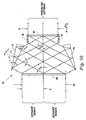
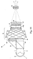
- Figure 10 shows a spatial integrator 70 where anamorphic beam compression and spatial integration of dual incoming beams has been performed using reflecting wedge prisms 72 and 74, and auxiliary planar side mirrors 76 and 78.
- the prism deviation angle ⁇ is 60°
- the entrance angle for the 60° linear microprismatic elements 80 and 82 is 60°.
- Figure 12 shows a polarization converter 86 that uses two reflecting prisms 88 and 90 and a single 60° microprismatic element 92 to spatially integrate the two beams and convert the aspect ratio.
- Collimated light enters a polarization beam splitter 94 where the p-polarized light is transmitted and s-polarized light is reflected and converted to p-polarized light by the half-wave retarder 96.
- the two beams enter reflecting prisms at a 45° entrance angle, are compressed by a factor C, and exit the prisms at an angle of 60°. There is a 75° deviation angle ⁇ between the input and exit beams of the reflecting prism.
- the compressed beams are then spatially integrated into a single collimated polarized beam by the 60° microprismatic element.
- a single panel LCD projection system was constructed as an optical breadboard to evaluate components of the current invention.
- a broadband 450-680 nm PBS cube (Melles Griot #03 PBB 007). produced a transmitted p-polarized beam and a reflected s-polarized beam.
- a 45° uncoated prism (Edmund Scientific #32531) deviated the reflected beam 90° by total internal reflection to be adjacent to the transmitted beam.
- the s-polarized beam was converted to a p-polarized beam by a half-wave retarder sheet (Polaroid #605208).
- a VGA compatible 1.3" diagonal monochrome LCD module (Seiko Epson #P13VM115/125), with an analyzer on the exit side, was illuminated by the collimated and polarized light beam exiting the wedge prism.
- a plano-convex field lens focused the light from the LCD module into a 3" focal length, f/2.5 coated anastigmat projection lens (JML Optical Industries).
- JML Optical Industries coated anastigmat projection lens
Landscapes
- Physics & Mathematics (AREA)
- General Physics & Mathematics (AREA)
- Optics & Photonics (AREA)
- Liquid Crystal (AREA)
- Polarising Elements (AREA)
- Video Image Reproduction Devices For Color Tv Systems (AREA)
Abstract
Description
- The present invention generally relates to optical illumination systems, and more particularly to a polarized illumination system having a novel spatial integrator, including variations for controlling aspect ratio, the system being suited for use with electronic projection displays, particularly of the liquid crystal display type.
- With the increasing use of liquid crystal display (LCD) devices in projection systems, there is a requirement for an efficient source of polarized light. Polarized light has been traditionally produced by an absorbing polarizer or a polarizing beam splitter (PBS) cube. For polarizing beam splitters, half of the light is reflected and this reflected polarized light is either thrown away, or converted to the same polarization as the transmitted beam. When converted, the reflected beam is then redirected to the LCD, along with the transmitted beam, to achieve a polarized light source that is brighter than one using a simple absorbing polarizer.
- An early application of converting polarized light in illumination systems was for automotive headlamps, as described by Zehender in "Headlights for Motor-Vehicles with Polarized Light," Lichttechnik, pp. 100-103 (1973). In this early design, no attempt was made to achieve spatial recombination of the separate beams, or to control the beam cross-section. With the advent of LCD projection systems, this technology achieved renewed interest, for example as described by Imai et al., "A Novel Polarization Converter for High-Brightness Liquid Crystal Light Valve Projector," SPIE Proceedings, vol. 1225, pp. 52-58 (1990), and Shinsuke et al., "A Polarization-Transforming Optics for a High Luminance LCD Projector," Proceedings of the SID, vol. 32/4, pp. 301-304 (1991).
- Japanese Patent Application (Kokai) No. 61-122626 describes a polarizing illumination device, that spatially integrates the separated beams at the LCD plane by means of a pair of wedge prisms. As shown in Figure 1, the device uses a
light source 1,collimator 2,PBS cube 3, right angle prism 4, half-wave retarder 5,wedge prisms LCD panel 8, andprojection lens 9. There must be a considerable distance between the wedge prisms and the LCD, since the beams are converging, and the incidence angle on the LCD must be kept small, which unduly restricts use of the device. - U.S. Patent Nos. 4,913,529 and 4,969,730 describe converting polarized light projection illumination systems using polarizing plates or a PBS cube, combining the separated beams at the LCD with steering prisms. U.S. Patent No. 5,381,278 uses converging and diverging lenses to redirect the separated beams to the LCD panel. Japanese Patent Application (Kokai) No. 71-99185 uses dual polarizing beam splitters, achieving a beam of oblong cross-section, but with no spatial recombination of the separate beams. European Patent Application No. 615,148 achieves polarization conversion and spatial recombination by recycling light backwards to the light source reflector, as does European Patent Application No. 573,905, assigned to Minnesota Mining and Manufacturing Co. (3M-assignee of the present invention). U.S. Patent No. 5,181,054 achieves spatial recombination of the separated beams by sending the beams through the LCD in opposite directions, as does U.S. Patent No. 5,428,469 (also assigned to 3M). U.S. Patent No. 5,446,510 achieves a common collimation angle for the separate beams, but without any spatial integration.
- U.S. Patent Nos. 5,042,921 and 5,124,841 describe polarization converters with spatial integration achieved by refracting microprisms. The polarization converter described in European Patent Application No. 463,500 preserves the aspect ratio of the original beam, but requires the use of two LCD's, and European Patent Application No. 456,427 matches the beam size to the LCD panel by the use of back reflections from a lamp reflector having a rectangular exit aperture. The efficiency of these systems is limited by the complexity of the optics, quality of the reflectance coatings, degree of spatial recombination and beam shaping, and high chromatic dispersion of the refracting elements.
- US 5 359 455 describes a polarization forming optical device comprising a light source, a polarization beam splitter, a half-wave plate, two mirrors and two prism formed plates. The light beam from the light source is split in two light beams by means of the beam splitter. One of the two light beams is rotated at 90° on the half-wave plate. The two beams are separately reflected by the two mirrors to the prism formed plate. The two beams are bent by the prism formed plate and thereafter partially reflected from the mirror to the second prism formed plate which is again bending the light beams.
- Spatial integration of the separate beams is important since the separated beams usually differ in intensity and color temperature. Collimation of the beam incident on the LCD is important, since most displays of this type work best with a common and low incidence angle of the illuminating light. Also, collimated light can be more efficiently focused by a field lens to the projection lens. Beam shaping is important to transmit maximum light through the rectangular aperture of the LCD. Lastly, compactness is desirable to reduce the size of the projector unit. None of the foregoing systems provides optimum performance in all of these areas.
- It is another object of the invention that there is negligible dispersion in an exit beam of an optical illumination system.
- These and other objects are solved by the invention according to
claims - The present invention provides a polarized illumination system particularly suited for an LCD projector, the system generally comprising a light source, means for collimating light from the source into an entrance beam, means for separating the entrance beam into a first beam having a first polarization state, and a second beam having a second polarization state, retarder means for converting said first beam from said first polarization state to said second polarization state, means for spatially integrating said first and second beams to create a collimated, exit beam having an aspect ratio, and means for changing the aspect ratio of said exit beam. The integrating means preferably comprises a spatial integrator cell having a first microprismatic element with a planar surface and a surface of prismatic grooves opposite said planar surface, and a second microprismatic element with another planar surface and another surface of prismatic grooves opposite the other planar surface and facing said surface of prismatic grooves on said first microprismatic element, there further being first and second, generally opposed reflecting surfaces adjacent first and second sides, respectively, of the second microprismatic element.
- The means for separating the light may comprise a polarizing beam splitter (PBS) which creates the first and second beams, and the PBS may be adapted to direct the first and second beams to first and second reflectorized wedge prisms, respectively. In several embodiments, the spatial integrator cell has an exit element which is combined with a first beam compression element, and a second beam compression element is positioned adjacent the first beam compression element to achieve the changed aspect ratio. The first beam compression element may be a positive cylinder Fresnel lens, and the second beam compression element a negative cylinder lens: Alternatively, the first beam compression element may be a first microprismatic element, and the second beam compression element a second microprismatic element positioned at an oblique angle with respect to the first microprismatic element. The means for changing the aspect ratio of the exit beam may further be designed to additionally cause the exit beam to deviate by approximately 90°.
- The current invention avoids many of the deficiencies of the prior art, by producing a converted secondary beam of collimated polarized light, and spatially recombining this beam with the primary beam using total internally reflective linear microprisms, preserving the polarization and collimation with minimal chromatic dispersion. The aspect ratio of the spatially integrated beam is then efficiently converted to match the format of an LCD panel. There is no requirement for any back-reflection or recycling of the beam in the direction of the light source, and the single collimated beam passing through the LCD panel can be more efficiently focused to the projection lens.
- The invention will best be understood by reference to the accompanying drawings, wherein:
- Figure 1 is a diagram of a prior art polarizing illumination device using wedge prism beam integrators;
- Figure 2 is a diagram of one embodiment of the polarized illumination system of the current invention;
- Figure 3 is a diagram of one configuration of the spatial integrator cell used in the present invention;
- Figure 3a is an enlargement of the linear microprismatic element structure on the spatial integrator of Figure 3;
- Figure 4 is a diagram of one type of prior art aspect ratio converter using positive and negative cylinder lenses;
- Figure 5 is a diagram showing application of positive/negative cylinder Fresnel lenses to the current invention;
- Figure 6 shows prior art anamorphic beam compression using identical prism pair, with minimal chromatic dispersion;
- Figure 7 is a diagram of a spatial integrator of the present invention with anamorphic beam compression using identical Fresnel prisms;
- Figure 8 is a diagram of anamorphic beam compression using a prismatic pair with 90° beam deviation and minimal chromatic dispersion;
- Figure 9 shows a reflective wedge prism as an anamorphic beam compressor;
- Figure 10 shows a combined spatial integrator/anamorphic beam compressor;
- Figure 11 shows an LCD projector using an embodiment of the current invention; and
- Figure 12 shows another embodiment of the current invention which eliminates the need for a right angle prism in conjunction with the PBS cube.
-
- With reference now to the figures, and in particular with reference to Figure 2, there is depicted one embodiment 10 of the polarized illumination system of the present invention. System 10 is particularly adapted for use with a liquid crystal display (LCD) projector, and the combination generally comprises a light source or
lamp 12, a collimator orparabolic reflector 14, means 16 for separating p- and s-polarized light, taking the form of a polarizing beam splitter (PBS), mean 18 for redirecting one of the polarized beams (in this case, the reflected beam) parallel with the other polarized beam (the transmitted beam), taking the form of a right angle prism reflector, a half-wave retarder plate 20, aspatial integrator cell 22, ananalyzer 24, anLCD panel 26, and aprojection lens 28. Embodiment 10 is a single-panel, transmissive LCD projector, but those skilled in the art will appreciate that the general principle can be extended to color and pseudo-color transmissive LCD projectors using multiple panels, as well as reflective LCD light valve projectors. - Randomly polarized light from
light source 12 is collimated by parabolic reflector 14 (or some other means) and entersPBS cube 16. The p-polarized light is transmitted and the reflected s-polarized light is turned 90° by rightangle reflecting prism 18, where it is then converted to p-polarized light by half-wave (λ/2)retarder plate 20. The adjacent and spatially separated collimated light beams enter the microprismaticspatial integrator cell 22 where they are spatially integrated and exit as a single collimated polarized beam. Components 12-18 are individually known in the prior art and nearly any conventional components will suffice. Therefore, in embodiment 10, the primary novelty resides inspatial integrator 22. - Figure 3 shows
spatial integrator cell 22. Each adjacent entrance beam is equally deviated by the firstmicroprismatic element 32, which consists of a series of 60° equilateral linear microprisms 34 (see Figure 3a). Half of the light passes directly to a second, oppositely disposedmicroprismatic element 36. The other half of the light is reflected off side mirrors 38 and 40, where it then passes to theopposite microprismatic element 36. By controlling the length ofcell 22, both beams exit the cell as a spatially integrated and collimated beam. The spatial integrator cell length L = A tan(π/6), where A is the half-height of the cell (see Figure 2), and light rays entering the center ofcell 22 exit at the edge of the cell. Figure 3a shows an enlarged section of firstlinear microprismatic element 32, where all the prism angles α = 60°, and the deviation angle δ = 60°. There is no refraction, hence no chromatic dispersion, at either microprismatic element since all ray deviations occur by total internal reflection (TIR), i.e., the angle of incidence at the interface between air and the microprismatic element is zero. For slight deviations from perfect collimation, there is substantially no chromatic dispersion for rays which are refracted at either surface, and also reflected from the TIR facets, since the microprisms are 60° equilateral triangles. - Since
PBS cube 16 forms adjacent square beams, each having an aspect ratio AR = 1:1, the polarization converted beam entering and exiting the spatial integrator cell has an AR = 2:1. Since most LCD panels have an AR = 4:3 = 1.33, the AR should be adjusted for efficient illumination of the LCD panel. One standard method of aspect ratio conversion that preserves the direction of the light beam is by the use of positive andnegative cylinder lenses cylinder Fresnel lens 46 in the exit surface of thespatial integrator cell 48, as shown if Figure 5. Thenegative cylinder lens 50 can be continuous or of the Fresnel type. - Another standard method of converting aspect ratio, or anamorphic beam compression, uses a pair of identical prisms as shown in Figure 6. The chromatic dispersion of the
first prism 52 is canceled by the opposite dispersion of thesecond prism 54, and the direction of the collimated light is preserved. A similar effect may be achieved in the current invention by forming the first element as a series of linear microprisms on theexit element 56 of aspatial integrator cell 58. A secondlinear microprismatic element 60 is then set at an oblique angle δ equal to the ray deviation of the first element, as shown in Figure 7. For example, for acrylic plastic (n d =1.492) with prism angles α = 40.52°, and δ = 35.25°, the aspect ratio of the beam is converted from 2/1 to 4/3, with no chromatic dispersion. - It is also possible to perform anamorphic beam compression in conjunction with the present invention with a 90° beam deviation, by using two prisms as shown in Figure 8. Here the first refracting
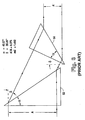
prism 62 is followed by asecond prism 64 that deviates the beam by refraction and total internal reflection. By specifying the vertex angles and tilt angles as shown, the chromatic dispersion of the first prism is canceled out by the dispersion of the second prism. For example, using optical crown glass (nd = 1.523) for both prisms, and 1 = 30°, 2 = 8°, α1 = 18.6°, α2 = 68°, α3 = 38.2°, then the beam is converted from an AR = 2:1 to an AR = 4:3 with negligble chromatic dispersion. - If a beam deviation of 90° is introduced between the spatial integrator and the LCD panel, there are several other methods of achieving the desired aspect ratio conversion. One method is shown in Figure 9, which utilizes a
reflective wedge prism 66. The incident beam, having an AR = 2:1 is converted to an output beam with an AR = 4:3 by specifying the tilt angle and the prism wedge angle α. Here - ≈ atan(A'/A), and
- α = ( - ')/2, where:
- A' = width of compressed exit beam,
- A = width of entrance beam,
- = angle of incidence of exiting reflected ray at refracting surface, and
- ' = angle of refraction of entrance ray at refracting surface.
-
- Figure 10 shows a
spatial integrator 70 where anamorphic beam compression and spatial integration of dual incoming beams has been performed using reflectingwedge prisms microprismatic elements - A'=(4/3) A,
- ≈ atan ((cos(π/6) - C cos(π/3)) / (C cos(π/3) + cos (π/6))), and
- α = ( - ')/2, where:
- C = anamorphic compression factor of wedge prism,
- = angle of incidence of exiting reflected ray at refracting surface of wedge prism,
- ' = angle of refraction of entrance ray at refracting surface of wedge prism, and
- = tilt angle of the wedge prisms.
-
- Figure 12 shows a
polarization converter 86 that uses two reflectingprisms microprismatic element 92 to spatially integrate the two beams and convert the aspect ratio. Collimated light enters apolarization beam splitter 94 where the p-polarized light is transmitted and s-polarized light is reflected and converted to p-polarized light by the half-wave retarder 96. The two beams enter reflecting prisms at a 45° entrance angle, are compressed by a factor C, and exit the prisms at an angle of 60°. There is a 75° deviation angle δ between the input and exit beams of the reflecting prism. The compressed beams are then spatially integrated into a single collimated polarized beam by the 60° microprismatic element. An incoming beam having an aspect ratio AR = 1 can be converted to an outgoing beam having an aspect ratio AR = 4:3 by the use of reflecting prisms having a refractive index n d= 1.523, a vertex angle α = 10.3°, a tilt angle = 26°, and an anamorphic compression factor C = 2/3. - A single panel LCD projection system was constructed as an optical breadboard to evaluate components of the current invention. A 24 volt, 250 watt tungsten-halogen lamp ( EHJ type ) having a spherical back reflector, produced a beam of collimated light of ≈ 50 mm diameter by means of a pair of glass condensing lenses. The beam was masked down to a 32 mm by 32 mm square aperture, and a piece of heat reflecting glass was positioned near this square aperture.
- A broadband 450-680 nm PBS cube (Melles Griot #03 PBB 007). produced a transmitted p-polarized beam and a reflected s-polarized beam. A 45° uncoated prism (Edmund Scientific #32531) deviated the reflected
beam 90° by total internal reflection to be adjacent to the transmitted beam. The s-polarized beam was converted to a p-polarized beam by a half-wave retarder sheet (Polaroid #605208). A spatial integrator cell was constructed using two linear 60° microprism elements, eachelement 32 mm wide by 64 mm high, of 2 mm thick acrylic, with each microprism width = 0.25 mm. The separation of the microprism elements was L = 18.5 mm. Spatial integration and common polarization of the two beams was verified by examining the output from the spatial integrator cell. - An anamorphic beam-compressing reflecting wedge prism was constructed from acrylic plastic (n d= 1.492), having a length of 100 mm, a width of 38 mm, and a wedge angle = 14.3°. The reflecting wedge prism changed the beam dimension exiting the spatial integrator from 64 mm by 32 mm (AR = 2:1) to 32 mm by 24 mm (AR=4:3).
- A VGA compatible 1.3" diagonal monochrome LCD module (Seiko Epson #P13VM115/125), with an analyzer on the exit side, was illuminated by the collimated and polarized light beam exiting the wedge prism. A plano-convex field lens focused the light from the LCD module into a 3" focal length, f/2.5 coated anastigmat projection lens (JML Optical Industries). Using a Spectra-Physics brightness spot meter, measured brightness increase of the projected screen image was ≈ 70 %, when the output of the converted polarized light was added to the primary beam.
- Although the invention has been described with reference to specific embodiments, this description is not meant to be construed in a limiting sense. Various modifications of the disclosed embodiment, as well as alternative embodiments of the invention, will become apparent to persons skilled in the art upon reference to the description of the invention. It is therefore contemplated that such modifications can be made without departing from the spirit or scope of the present invention as defined in the appended claims.
Claims (18)
- An article for spatially integrating two or more collimated light beams, comprising:a first reflecting surface (38),a second reflecting surface (40) generally opposed to said first reflecting surface,a first microprismatic element (32) having a series of approximately 60° equilateral linear microprisms for deviating light from the light beams by total internal reflection between and onto said first and second reflecting surfaces (38,40), anda second microprismatic element (36) having a series of approximately 60° equilateral linear microprisms for collecting light so deviated from the light beams and reflected off of said first and second reflecting surfaces (38,40) and collimating the collected light by total internal reflection into an exit beam.
- The article of claim 1 wherein said first and second reflecting surfaces (38,40) are parallel.
- The article of claim 1 wherein said first and second reflecting surfaces (38,40) are formed on first and second reflectorized wedge prisms (62,64), respectively.
- The article of claim 1 further comprising a polarizing beam splitter (16).
- The article of claim 1 wherein said first microprismatic element (32,36) further comprises a planar surface facing the incident two light beams opposite said surface of prismatic grooves.
- The article of claim 1 wherein said second microprismatic element (36) comprises a surface of prismatic grooves facing the two light beams, and a planar surface opposite said groove surface.
- The article of claim 1 wherein said first and second microprismatic elements (32,36) cause substantially no chromatic dispersion.
- The article of claim 1 wherein the exit beam has an aspect ratio, and said second microprismatic element (36) includes a first beam compression element (52), and further comprising a second beam compression element (54) positioned adjacent said first beam compression element (52) to change the aspect ratio of the exit beam.
- The article of claim 1 further comprising a polarizing beam splitter (16) which creates the two collimated beams from a single collimated beam, a first of the two collimated beams having a first polarization state, and a second of the two collimated beams having a second polarization state,
and wherein said first prismatic element directs the first collimated beam to said first reflectorized wedge prism (62), and directs the second collimated beam to said second reflectorized wedge prism (64), and
a half-wave retarder is interposed between said polarizing beam splitter (16) and said first reflectorized wedge prism (62). - The article of claim 5 wherein said second microprismatic element (36) is generally parallel to said first microprismatic element (32) and comprises a surface of prismatic grooves facing the two light beams, and a planar surface opposite said groove surface.
- A polarized illumination system comprising:wherein said integrating means includes:a light source,means for collimating light from said source into an entrance beam,means (94) for separating said entrance beam into a first beam having a first polarization state, and a second beam having a second polarization state,means (96) for converting said first beam from said first polarization state to said second polarization state,means for spatially integrating said first and second beams to create a collimated exit beam having an aspect ration, andmeans for changing the aspect ratio of said exit beam by means of reflecting wedge prisms (88,90),a first microprismatic element (80) having a planar surface and a surface of prismatic grooves having a series of approximately 60° equilateral linear microprisms opposite said planar surface,a second microprismatic element (92) having another planar surface and another surface of prismatic grooves having a series of approximately 60° equilateral linear microprisms opposite to said other planar surface and facing said surface of prismatic grooves on said first microprismatic element (80),a first reflecting surface (88) adjacent a first side of said second microprismatic element (92), anda second reflecting surface (90) adjacent a second side of said second microprismatic element (92), said second reflecting surface (90) being generally opposed to said first reflecting surface (80).
- The polarized illumination system of claim 11 wherein:said means (94) for separating light comprises a polarization beam splitter which creates the first and second beams,said means for spatially integrating said first and second beams includes first and second reflectorized wedge prisms (88,90), andsaid polarizing beam splitter directs the first beam to said first reflectorized wedge prism (88), and directs the second beam to said second reflectorized wedge prism (90).
- The polarized illumination system of claim 11 wherein:said means for spatially integrating said first and second beams includes a spatial integrator cell having an exit element, andsaid means for changing the aspect ratio of said exit beam includes a first beam compression element attached to said exit element, and a second beam compression element positioned adjacent said first beam compression element.
- The polarized illumination system of claim 11 wherein said means for changing the aspect ratio of said exit beam also causes said exit beam to deviate by approximately 90°.
- The polarized illumination system of claim 11 wherein said first and second reflecting surfaces (88,90) are respectively comprised of first and second auxiliary planar mirrors, and further comprising:a first reflectorized wedge prism (88) located between said first and second microprismatic elements, proximate said first auxiliary planar mirror, anda second reflectorized wedge prism (90) located between said first and second microprismatic elements (80,92), proximate said second auxiliary planar mirror and generally opposed to said first reflectorized wedge prism.
- The polarized illumination system of claim 13 wherein:said first beam compression element is a positive cylinder Fresnel lens, andsaid second beam compression element is a negative cylinder lens.
- The polarized illumination system of claim 13 wherein:said first beam compression element is a first microprismatic element, andsaid second beam compression element is a second microprismatic element positioned at an oblique angle with respect to said first microprismatic element.
- An electronic projector comprising:a light source (12),means (14) for collimating light from said source into an entrance beam,means (16) for separating said entrance beam into a first beam having a first polarization state, and a second beam having a second polarization state,a half-wave retarder (20) adjacent said separating means for converting said first beam from said first polarization state to said second polarization state,a spatial integrator cell (22) positioned to receive the first and second beams, said cell (22) including a first reflecting surface, a second reflecting surface generally opposed to said first reflecting surface, a first microprismatic element (32) having a series of approximately 60° equilateral linear microprisms for deviating light from the first and second beams by total internal reflection between and onto said first and second reflecting surfaces, and second microprismatic element (36) having a series of approximately 60° equilateral linear microprisms for collecting light so deviated from the light beams and reflected off of said first and second reflecting surfaces, and for collimating the collceted light by total internal reflection into an exit beam having an aspect ratio,means for changing the aspect ratio of said exit beam, including a first beam compression element attached to said exit element, and a second beam compression element positioned adjacent said first beam compression element,display means positioned to receive the exit beam having the changed aspect ratio,a projection lens (28), anda field lens positioned to direct light from said display means (26) to said projection lens (28).
Applications Claiming Priority (3)
| Application Number | Priority Date | Filing Date | Title |
|---|---|---|---|
| US08/625,030 US5995284A (en) | 1996-03-29 | 1996-03-29 | Polarized illumination system for LCD projector |
| US625030 | 1996-03-29 | ||
| PCT/US1997/004565 WO1997037266A1 (en) | 1996-03-29 | 1997-03-17 | Polarized illumination system for lcd projector |
Publications (2)
| Publication Number | Publication Date |
|---|---|
| EP0890128A1 EP0890128A1 (en) | 1999-01-13 |
| EP0890128B1 true EP0890128B1 (en) | 2002-06-05 |
Family
ID=24504296
Family Applications (1)
| Application Number | Title | Priority Date | Filing Date |
|---|---|---|---|
| EP97919891A Expired - Lifetime EP0890128B1 (en) | 1996-03-29 | 1997-03-17 | Polarized illumination system for lcd projector |
Country Status (11)
| Country | Link |
|---|---|
| US (1) | US5995284A (en) |
| EP (1) | EP0890128B1 (en) |
| JP (1) | JP2001501317A (en) |
| KR (1) | KR100456492B1 (en) |
| CN (1) | CN1214775A (en) |
| AU (1) | AU2421697A (en) |
| CA (1) | CA2247435A1 (en) |
| DE (1) | DE69713081T2 (en) |
| ES (1) | ES2175397T3 (en) |
| TW (1) | TW307832B (en) |
| WO (1) | WO1997037266A1 (en) |
Families Citing this family (27)
| Publication number | Priority date | Publication date | Assignee | Title |
|---|---|---|---|---|
| WO1998031143A2 (en) * | 1997-01-10 | 1998-07-16 | Koninklijke Philips Electronics N.V. | Illumination system for an image projection device |
| US7710669B2 (en) * | 2000-08-24 | 2010-05-04 | Wavien, Inc. | Etendue efficient combination of multiple light sources |
| US6587269B2 (en) * | 2000-08-24 | 2003-07-01 | Cogent Light Technologies Inc. | Polarization recovery system for projection displays |
| KR100571909B1 (en) * | 2000-09-21 | 2006-04-17 | 삼성전자주식회사 | Projection type image display apparatus |
| US6739723B1 (en) | 2001-12-07 | 2004-05-25 | Delta Electronics, Inc. | Polarization recapture system for liquid crystal-based data projectors |
| US20030112511A1 (en) * | 2001-12-19 | 2003-06-19 | Koninklijke Philips Electronics N.V. | Polarization conversion method for liquid crystal displays |
| US6646806B1 (en) * | 2002-05-17 | 2003-11-11 | Infocus Corporation | Polarized light source system with dual optical paths |
| US20050174641A1 (en) * | 2002-11-26 | 2005-08-11 | Jds Uniphase Corporation | Polarization conversion light integrator |
| JP2004214073A (en) * | 2003-01-07 | 2004-07-29 | Honda Motor Co Ltd | Enunciator lantern |
| US20040207774A1 (en) * | 2003-04-17 | 2004-10-21 | Gothard David L. | Illumination apparatus for LCD/organic displays |
| US20050041288A1 (en) * | 2003-08-19 | 2005-02-24 | Liao Liu Liang | Polarization conversion module and polarization conversion method thereof |
| DE10361559A1 (en) * | 2003-12-19 | 2005-07-14 | Carl Zeiss Jena Gmbh | Projection arrangement for use in digital projector of e.g. LCD, has deflective unit with spherically formed reflective surface that is arranged approximately at forty five degrees with respect to principal axes of three lenses |
| JP2007537461A (en) * | 2004-03-11 | 2007-12-20 | トムソン ライセンシング | Multiple lamp illumination system with polarization recovery and integration |
| US20080129964A1 (en) * | 2006-11-30 | 2008-06-05 | Upstream Engineering Oy | Beam shaping component and method |
| TW200839292A (en) * | 2006-11-30 | 2008-10-01 | Upstream Engineering Oy | Beam shaping method and apparatus |
| JP2007192841A (en) * | 2007-04-24 | 2007-08-02 | Fujifilm Corp | Measurement method and instrument utilizing total attenuated reflection |
| JP5110979B2 (en) * | 2007-06-26 | 2012-12-26 | キヤノン株式会社 | Illumination optical system and projection display device using the same |
| US8905547B2 (en) * | 2010-01-04 | 2014-12-09 | Elbit Systems Of America, Llc | System and method for efficiently delivering rays from a light source to create an image |
| TWI418917B (en) * | 2010-10-15 | 2013-12-11 | Young Optics Inc | Projection device |
| US10386558B2 (en) | 2013-03-13 | 2019-08-20 | Imagineoptix Corporation | Polarization conversion systems with geometric phase holograms |
| CN103644487A (en) * | 2013-12-30 | 2014-03-19 | 北京理工大学 | Light-emitting diode (LED) runway center line lamp optical system based on free curved lens |
| US9778475B2 (en) * | 2014-11-06 | 2017-10-03 | The United States of America as represesnted by the Secretary of the Air Forice | Universal polarization converter |
| WO2017021833A1 (en) | 2015-08-05 | 2017-02-09 | Spectrum Optix Inc. | Flat wedge-shaped lens and image processing method |
| CN106405933B (en) | 2016-10-31 | 2019-08-13 | 京东方科技集团股份有限公司 | Backlight module and liquid crystal display device |
| US10620348B2 (en) * | 2016-12-09 | 2020-04-14 | Lumenflow | Lower index-gap corrective wedge prism |
| CN114200756B (en) * | 2020-09-18 | 2023-04-18 | 中强光电股份有限公司 | Illumination system and projection device |
| CN114200760A (en) * | 2021-11-05 | 2022-03-18 | 杭州中科极光科技有限公司 | Laser display light source system and laser display equipment |
Family Cites Families (24)
| Publication number | Priority date | Publication date | Assignee | Title |
|---|---|---|---|---|
| DE152212C (en) * | ||||
| US3743380A (en) * | 1972-01-31 | 1973-07-03 | Us Navy | Polarized light source for underwater use |
| DD152212A1 (en) * | 1980-07-15 | 1981-11-18 | Volkmar Norkus | OPTICAL SYSTEM FOR CONVERTING THE POLARIZATION OF LIGHT |
| JPH061303B2 (en) * | 1984-11-20 | 1994-01-05 | ソニー株式会社 | Polarized illumination device |
| NL8802517A (en) * | 1988-10-13 | 1990-05-01 | Philips Nv | IMAGE PROJECTION DEVICE. |
| US5042921A (en) * | 1988-10-25 | 1991-08-27 | Casio Computer Co., Ltd. | Liquid crystal display apparatus |
| US4913529A (en) * | 1988-12-27 | 1990-04-03 | North American Philips Corp. | Illumination system for an LCD display system |
| EP0422661A3 (en) * | 1989-10-13 | 1992-07-01 | Mitsubishi Rayon Co., Ltd | Polarization forming optical device and polarization beam splitter |
| DE69028497T2 (en) * | 1989-12-20 | 1997-02-06 | Canon Kk | Polarizing lighting device |
| DE69025924T2 (en) * | 1989-12-26 | 1996-11-14 | Mitsubishi Rayon Co | OPTICAL DEVICE FOR GENERATING POLARIZED LIGHT |
| JP2828297B2 (en) * | 1990-01-19 | 1998-11-25 | 旭光学工業株式会社 | Reflective projector |
| FR2660448B1 (en) * | 1990-04-03 | 1992-06-05 | Thomson Csf | DEVICE FOR PROJECTING IMAGES. |
| ATE162921T1 (en) * | 1990-05-08 | 1998-02-15 | Canon Kk | POLARIZATION CONVERSION APPARATUS |
| JP3126368B2 (en) * | 1990-06-22 | 2001-01-22 | 株式会社日立製作所 | Image reduction / enlargement projection device |
| FR2665773B1 (en) * | 1990-08-10 | 1993-08-20 | Thomson Csf | IMAGE PROJECTION DEVICE USING TWO ORTHOGONAL LIGHT POLARIZATION COMPONENTS. |
| US5381278A (en) * | 1991-05-07 | 1995-01-10 | Canon Kabushiki Kaisha | Polarization conversion unit, polarization illumination apparatus provided with the unit, and projector provided with the apparatus |
| JPH05241103A (en) * | 1992-02-21 | 1993-09-21 | Nec Corp | Projection type liquid crystal display device |
| EP0573905A1 (en) * | 1992-06-08 | 1993-12-15 | Minnesota Mining And Manufacturing Company | Retroreflecting polarizer for presentation systems |
| US5347433A (en) * | 1992-06-11 | 1994-09-13 | Sedlmayr Steven R | Collimated beam of light and systems and methods for implementation thereof |
| DE4307178C2 (en) * | 1993-03-08 | 1996-09-19 | Lueder Ernst | Device and method for polarizing light |
| US5428469A (en) * | 1993-11-16 | 1995-06-27 | Minnesota Mining And Manufacturing Company | Liquid crystal display projection systems employing polarizing beam splitters and passing light through display cell from both directions |
| JPH07199185A (en) * | 1993-12-27 | 1995-08-04 | Nec Corp | Projection type liquid crystal display device |
| WO1996005534A1 (en) * | 1994-08-09 | 1996-02-22 | Philips Electronics N.V. | Illumination system for supplying a polarized radiation beam, and image projection device comprising such an illumination system |
| US5504544A (en) * | 1994-11-23 | 1996-04-02 | Minnesota Mining And Manufacturing Company | Projector with multiple lamp light source |
-
1996
- 1996-03-29 US US08/625,030 patent/US5995284A/en not_active Expired - Fee Related
- 1996-04-22 TW TW085104786A patent/TW307832B/en active
-
1997
- 1997-03-17 JP JP09535322A patent/JP2001501317A/en not_active Ceased
- 1997-03-17 KR KR10-1998-0707698A patent/KR100456492B1/en not_active IP Right Cessation
- 1997-03-17 WO PCT/US1997/004565 patent/WO1997037266A1/en active IP Right Grant
- 1997-03-17 CA CA002247435A patent/CA2247435A1/en not_active Abandoned
- 1997-03-17 ES ES97919891T patent/ES2175397T3/en not_active Expired - Lifetime
- 1997-03-17 DE DE69713081T patent/DE69713081T2/en not_active Expired - Fee Related
- 1997-03-17 EP EP97919891A patent/EP0890128B1/en not_active Expired - Lifetime
- 1997-03-17 CN CN97193360A patent/CN1214775A/en active Pending
- 1997-03-17 AU AU24216/97A patent/AU2421697A/en not_active Abandoned
Also Published As
| Publication number | Publication date |
|---|---|
| ES2175397T3 (en) | 2002-11-16 |
| KR100456492B1 (en) | 2005-01-15 |
| CA2247435A1 (en) | 1997-10-09 |
| CN1214775A (en) | 1999-04-21 |
| AU2421697A (en) | 1997-10-22 |
| WO1997037266A1 (en) | 1997-10-09 |
| JP2001501317A (en) | 2001-01-30 |
| KR20000005070A (en) | 2000-01-25 |
| DE69713081T2 (en) | 2003-01-23 |
| DE69713081D1 (en) | 2002-07-11 |
| US5995284A (en) | 1999-11-30 |
| TW307832B (en) | 1997-06-11 |
| EP0890128A1 (en) | 1999-01-13 |
Similar Documents
| Publication | Publication Date | Title |
|---|---|---|
| EP0890128B1 (en) | Polarized illumination system for lcd projector | |
| US6406149B2 (en) | Illuminating apparatus and projecting apparatus | |
| US5278680A (en) | Projection type liquid crystal display system and method of polarized light component projection | |
| US5940149A (en) | Planar polarizer for LCD projectors | |
| US5896232A (en) | Highly efficient and compact frontlighting for polarization-based reflection light valves | |
| US5884991A (en) | LCD projection system with polarization doubler | |
| US6310713B2 (en) | Optical system for miniature personal displays using reflective light valves | |
| US20010028412A1 (en) | Projector | |
| US5973833A (en) | High efficiency polarizing converter | |
| JP2001215613A (en) | Projector | |
| JPH08271854A (en) | Device for projection of image of light source | |
| EP0997768A2 (en) | Illumination device and projection type display apparatus | |
| US5911489A (en) | Optical lighting system | |
| US5900973A (en) | Optical polarization device and projection system of liquid crystal valve type utilizing such a device | |
| US6987618B2 (en) | Polarization converting device, illumination optical system and projector | |
| US6803972B1 (en) | Polarization conversion system | |
| JP2002258212A (en) | Lighting system for projector | |
| JPH06289387A (en) | Illuminating optical system and projection type display device | |
| US5890786A (en) | Projection apparatus | |
| US20040190149A1 (en) | Image projection system and polarizing beam splitter | |
| JPH07239473A (en) | Projection type liquid crystal display device | |
| KR100335437B1 (en) | Reflection type projector | |
| JP3591026B2 (en) | Illumination device and projection display device using the same | |
| JPH1010467A (en) | Projection and display device | |
| KR20010054283A (en) | Optical System Of Liquid Crystal Projector Using Two Lamps |
Legal Events
| Date | Code | Title | Description |
|---|---|---|---|
| PUAI | Public reference made under article 153(3) epc to a published international application that has entered the european phase |
Free format text: ORIGINAL CODE: 0009012 |
|
| 17P | Request for examination filed |
Effective date: 19980902 |
|
| AK | Designated contracting states |
Kind code of ref document: A1 Designated state(s): DE ES FR GB IT |
|
| 17Q | First examination report despatched |
Effective date: 19991227 |
|
| GRAG | Despatch of communication of intention to grant |
Free format text: ORIGINAL CODE: EPIDOS AGRA |
|
| GRAG | Despatch of communication of intention to grant |
Free format text: ORIGINAL CODE: EPIDOS AGRA |
|
| GRAH | Despatch of communication of intention to grant a patent |
Free format text: ORIGINAL CODE: EPIDOS IGRA |
|
| GRAH | Despatch of communication of intention to grant a patent |
Free format text: ORIGINAL CODE: EPIDOS IGRA |
|
| GRAA | (expected) grant |
Free format text: ORIGINAL CODE: 0009210 |
|
| AK | Designated contracting states |
Kind code of ref document: B1 Designated state(s): DE ES FR GB IT |
|
| REG | Reference to a national code |
Ref country code: GB Ref legal event code: FG4D |
|
| REF | Corresponds to: |
Ref document number: 69713081 Country of ref document: DE Date of ref document: 20020711 |
|
| ET | Fr: translation filed | ||
| REG | Reference to a national code |
Ref country code: ES Ref legal event code: FG2A Ref document number: 2175397 Country of ref document: ES Kind code of ref document: T3 |
|
| PLBE | No opposition filed within time limit |
Free format text: ORIGINAL CODE: 0009261 |
|
| STAA | Information on the status of an ep patent application or granted ep patent |
Free format text: STATUS: NO OPPOSITION FILED WITHIN TIME LIMIT |
|
| 26N | No opposition filed |
Effective date: 20030306 |
|
| PGFP | Annual fee paid to national office [announced via postgrant information from national office to epo] |
Ref country code: ES Payment date: 20060327 Year of fee payment: 10 |
|
| PGFP | Annual fee paid to national office [announced via postgrant information from national office to epo] |
Ref country code: IT Payment date: 20060331 Year of fee payment: 10 |
|
| PGFP | Annual fee paid to national office [announced via postgrant information from national office to epo] |
Ref country code: GB Payment date: 20080327 Year of fee payment: 12 |
|
| REG | Reference to a national code |
Ref country code: ES Ref legal event code: FD2A Effective date: 20070319 |
|
| PG25 | Lapsed in a contracting state [announced via postgrant information from national office to epo] |
Ref country code: ES Free format text: LAPSE BECAUSE OF NON-PAYMENT OF DUE FEES Effective date: 20070319 |
|
| PGFP | Annual fee paid to national office [announced via postgrant information from national office to epo] |
Ref country code: FR Payment date: 20080317 Year of fee payment: 12 Ref country code: DE Payment date: 20080430 Year of fee payment: 12 |
|
| PG25 | Lapsed in a contracting state [announced via postgrant information from national office to epo] |
Ref country code: IT Free format text: LAPSE BECAUSE OF NON-PAYMENT OF DUE FEES Effective date: 20070317 |
|
| GBPC | Gb: european patent ceased through non-payment of renewal fee |
Effective date: 20090317 |
|
| REG | Reference to a national code |
Ref country code: FR Ref legal event code: ST Effective date: 20091130 |
|
| PG25 | Lapsed in a contracting state [announced via postgrant information from national office to epo] |
Ref country code: DE Free format text: LAPSE BECAUSE OF NON-PAYMENT OF DUE FEES Effective date: 20091001 |
|
| PG25 | Lapsed in a contracting state [announced via postgrant information from national office to epo] |
Ref country code: GB Free format text: LAPSE BECAUSE OF NON-PAYMENT OF DUE FEES Effective date: 20090317 Ref country code: FR Free format text: LAPSE BECAUSE OF NON-PAYMENT OF DUE FEES Effective date: 20091123 |