EP0889653A2 - Image predictive decoding method using a plurality of motion compensation modes and motion information from adjacent regions - Google Patents
Image predictive decoding method using a plurality of motion compensation modes and motion information from adjacent regions Download PDFInfo
- Publication number
- EP0889653A2 EP0889653A2 EP98112463A EP98112463A EP0889653A2 EP 0889653 A2 EP0889653 A2 EP 0889653A2 EP 98112463 A EP98112463 A EP 98112463A EP 98112463 A EP98112463 A EP 98112463A EP 0889653 A2 EP0889653 A2 EP 0889653A2
- Authority
- EP
- European Patent Office
- Prior art keywords
- region
- predictive
- data
- target
- motion vector
- Prior art date
- Legal status (The legal status is an assumption and is not a legal conclusion. Google has not performed a legal analysis and makes no representation as to the accuracy of the status listed.)
- Withdrawn
Links
Images


Classifications
-
- H—ELECTRICITY
- H04—ELECTRIC COMMUNICATION TECHNIQUE
- H04N—PICTORIAL COMMUNICATION, e.g. TELEVISION
- H04N19/00—Methods or arrangements for coding, decoding, compressing or decompressing digital video signals
- H04N19/10—Methods or arrangements for coding, decoding, compressing or decompressing digital video signals using adaptive coding
- H04N19/102—Methods or arrangements for coding, decoding, compressing or decompressing digital video signals using adaptive coding characterised by the element, parameter or selection affected or controlled by the adaptive coding
- H04N19/103—Selection of coding mode or of prediction mode
- H04N19/105—Selection of the reference unit for prediction within a chosen coding or prediction mode, e.g. adaptive choice of position and number of pixels used for prediction
-
- H—ELECTRICITY
- H04—ELECTRIC COMMUNICATION TECHNIQUE
- H04N—PICTORIAL COMMUNICATION, e.g. TELEVISION
- H04N19/00—Methods or arrangements for coding, decoding, compressing or decompressing digital video signals
- H04N19/10—Methods or arrangements for coding, decoding, compressing or decompressing digital video signals using adaptive coding
- H04N19/102—Methods or arrangements for coding, decoding, compressing or decompressing digital video signals using adaptive coding characterised by the element, parameter or selection affected or controlled by the adaptive coding
- H04N19/103—Selection of coding mode or of prediction mode
- H04N19/112—Selection of coding mode or of prediction mode according to a given display mode, e.g. for interlaced or progressive display mode
-
- H—ELECTRICITY
- H04—ELECTRIC COMMUNICATION TECHNIQUE
- H04N—PICTORIAL COMMUNICATION, e.g. TELEVISION
- H04N19/00—Methods or arrangements for coding, decoding, compressing or decompressing digital video signals
- H04N19/10—Methods or arrangements for coding, decoding, compressing or decompressing digital video signals using adaptive coding
- H04N19/134—Methods or arrangements for coding, decoding, compressing or decompressing digital video signals using adaptive coding characterised by the element, parameter or criterion affecting or controlling the adaptive coding
- H04N19/136—Incoming video signal characteristics or properties
- H04N19/137—Motion inside a coding unit, e.g. average field, frame or block difference
-
- H—ELECTRICITY
- H04—ELECTRIC COMMUNICATION TECHNIQUE
- H04N—PICTORIAL COMMUNICATION, e.g. TELEVISION
- H04N19/00—Methods or arrangements for coding, decoding, compressing or decompressing digital video signals
- H04N19/50—Methods or arrangements for coding, decoding, compressing or decompressing digital video signals using predictive coding
- H04N19/503—Methods or arrangements for coding, decoding, compressing or decompressing digital video signals using predictive coding involving temporal prediction
- H04N19/51—Motion estimation or motion compensation
- H04N19/56—Motion estimation with initialisation of the vector search, e.g. estimating a good candidate to initiate a search
-
- H—ELECTRICITY
- H04—ELECTRIC COMMUNICATION TECHNIQUE
- H04N—PICTORIAL COMMUNICATION, e.g. TELEVISION
- H04N19/00—Methods or arrangements for coding, decoding, compressing or decompressing digital video signals
- H04N19/50—Methods or arrangements for coding, decoding, compressing or decompressing digital video signals using predictive coding
- H04N19/503—Methods or arrangements for coding, decoding, compressing or decompressing digital video signals using predictive coding involving temporal prediction
- H04N19/51—Motion estimation or motion compensation
- H04N19/583—Motion compensation with overlapping blocks
Definitions
- the present invention relates to an image predictive decoding method of predictively decoding a compressed digital image and, more particularly, to an overlapped compensation method for interlaced images, an apparatus for performing the method, and a data storage medium for storing the method.
- Compressive coding is required to store and transmit a digital image efficiently.
- DCT Discrete Cosine Transform
- waveform coding i.e., sub-band coding, wavelet coding, and fractal coding.
- inter-image prediction using motion compensation is performed, and a difference signal is subjected to waveform coding.
- MPEG which is based on motion compensation DCT, will be described.
- An input image to be processed is divided into a plurality of 16x16 macroblocks.
- Each 16x16 macroblock is further divided into 8x8 blocks.
- Each 8x8 block is subjected to DCT.
- the resulting transform coefficients are quantized and then, transmitted or stored. This is called intra-frame coding.
- a predictive macroblock which has the least error to a target macroblock of a frame, is detected among macroblocks of another frame temporally adjacent to the former frame. Motion is also detected. An optimal predictive block is obtained by subjecting a previous image to motion compensation based on the detected motion. A signal indicating a predictive macroblock having the least error is a motion vector. An image to be referred for generating a predictive macroblock is a reference image.
- a difference between a target block among the 8x8 blocks into which the input image is divided, and its corresponding predictive block, is calculated.
- the difference is subjected to DCT, its transform coefficients are quantized, and the result is transmitted or stored along with motion information. This is inter-frame coding.
- the difference signal is restored from the quantized transform coefficients.
- a predictive block corresponding to the target block is calculated based on the motion vector transmitted or stored. The predictive block is added with the difference signal to reproduce the image.
- MPEG2 has two motion compensation modes for an interlaced image, i.e., a frame motion compensation mode and a field motion compensation mode.
- a frame motion compensation mode the data of an odd-numbered field and an even-number field of a block to be decoded are calculated based on the same motion vector.
- the field motion compensation mode the data of an odd-numbered field and an even-number field are obtained from two different motion vectors.
- interlaced scanning an odd-number field and an even-numbered field are scanned at different moments, so there is sometimes a large difference in the amount of motion between both of the fields.
- a predictive block is generated in a way in which in addition to a motion vector of a target block to be decoded, motion vectors of blocks adjacent to the target block are used to produce predictive data, and the weighted average of the predicted data is calculated, which is a predictive block.
- This is called overlapped motion compensation.
- overlapped motion compensation the errors of the predictive signal to a target block and the predictive signals to all adjacent blocks are averaged, thereby suppressing the difference signal, and reducing distortion between blocks, i.e., a phenomenon where the border between two blocks is clearly perceivable, as observed in cases where motion compensation is performed block by block.
- the error of a predictive signal is required to be small.
- the interlaced image is processed with the frame motion compensation mode and the field motion compensation mode, so that there is a case where two adjacent blocks are subjected to motion compensation with different modes.
- the frame motion compensation mode is effective for a static region in which a high-frequency component between scanning lines is small.
- the field motion compensation mode is suitable for a region having a large motion in which a high-frequency component between scanning lines is large.
- the overlapped motion compensation introduces a high-frequency component to the predictive signal of the target block.
- the averaging in the overlapped motion compensation reduces the temporal resolution of a predictive signal, thereby blurring a motion in the region having a large motion.
- an image predictive decoding method including
- an image predictive decoding method including
- the image predictive decoding method of any of the first and second aspects includes, as the motion compensation mode,
- an image predictive decoding method including
- an image predictive decoding method including
- an image predictive decoding method including
- a target block when a target block is in the frame predictive mode while the adjacent region is in the field predictive mode, it is possible to suppress the error of a predictive signal by using the field motion vector of the adjacent block close to the frame motion vector of the target block, while getting around the problems that the overlapped motion compensation introduces high-frequency components to a static region, and that the motion in a region having a large motion blurs due to a reduction in the temporal resolution of a predictive signal by averaging in the overlapped motion compensation.
- an image predictive decoding method including
- an image predictive decoding method including
- the image predictive decoding method of the eighth aspect wherein when the target region is in the frame motion compensation mode, optimal predictive region data to the target region is calculated in a way in which it is decided whether each adjacent region to the target region is in the field motion compensation mode, or not, and when the adjacent region is in the field motion compensation mode, the first and second motion vectors of the adjacent region are averaged, predictive region data to the adjacent region is calculated based on the averaged field motion vector of the adjacent region, and the target predictive region data and all of the adjacent predictive region data are averaged to produce the optimal predictive data to the target region.
- an image predictive decoding apparatus comprising:
- an image predictive coding apparatus comprising:
- a data storage medium storing a program for performing the image predictive decoding method of any of the first to ninth aspects, using a computer.
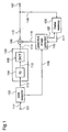
- Fig. 1 is a block diagram of an image predictive decoding apparatus according to a first embodiment of this invention.
- overlapped motion compensation is carried out by calculating predictive region data based on the motion vectors of only adjacent regions having the same motion compensation mode as a target region. That is, the overlapped motion compensation is performed in the following way.
- First predictive region data which are the predictive region data to adjacent regions, are calculated by using the motion vectors of only adjacent regions having the same motion compensation mode as a target region.
- the first predictive region data, and the target predictive region data calculated based on the motion vector of the target region are averaged to obtain optimal predictive region data.
- reference numeral 101 denotes an input terminal into which compressively coded data is input; 102, a data analyzer analyzing data input through the input terminal 101 via a line 111; 103, a transformation decoder subjecting the analyzed data to transformation decoding, comprising an inverse quantizer 104 , or IQ for short, and ⁇ an inverse discrete cosine transformer 105, or IDCT for short; 110, a predictive image generator generating a predictive image using information about a motion compensation mode, and a motion vector, from the data analyzer 102 via a line 118; 106, an adder adding an output of the IDCT 105 via a line 114, and a predictive image signal from the predictive image generator 110 via a line 119; 107, an output terminal through which an output of the adder 106 is output via a line 115; and 109, a frame memory to which an output of the adder 106 is input via the line 115 and, further, a line 116.
- Compressively coded data is input through the input terminal 101.
- compressively coding data an image is divided into a plurality of small regions, each small region is subjected to DCT to transform it to the frequency region.
- the small region into which the image is divided is a block constituted by 8x8 elements, the way of division is not necessarily restricted to this.
- Transform coefficients resulting from performance of DCT are subjected to quantization with a predetermined size of quantization step. Further, a result of the quantization is subjected to variable length coding.
- the data of a predictive region is calculated by motion compensation using a motion vector corresponding to the motion compensation mode minimizing a difference between the data of a target region and the data of the corresponding predictive region.
- a difference between the data of a target region to be coded, and the data of the predictive region, is transformed by DCT, and the result is quantized.
- the compressively coded data further includes the quantization step size, the transform coefficients resulting from the quantization, the motion vector of the motion compensation mode minimizing the difference, and the information about motion compensation modes.
- the motion compensation mode there are the frame motion compensation mode and the field motion compensation mode used in MPEG2, and the overlapped motion compensation mode used in H.263. The above description is for the coding side.
- the data input through the input terminal 101 is analyzed in the data analyzer 102.
- the quantization step and the quantized transform coefficients are transmitted via the line 112 to the transformation decoder 103, while the information about motion compensation modes, and the motion vector are output to the predictive image generator 110 via the line 118.
- the transformation decoder 103 decompresses the quantized transform coefficients to restore the difference data decompressed.
- the transform coefficients quantized using a quantization step are inversely quantized by the inverse quantizer 104, and then, the transform coefficients in the frequency region are transformed to spatial region signals by the IDCT 105.
- the predictive image generator 110 generates an address 120 for accessing the frame memory 109 based on the motion vector corresponding to information about a motion compensation mode, and generates a predictive block based on an image stored in the frame memory 109, input via the line 117.
- the predictive block generated the predictive image generator 110 and the difference block decompressed by the IDCT 105 are input to the adder 106 via the lines 119 and 114, respectively.
- the addition produces a reproduced block to be output via the line 115.
- the thus-reproduced image is stored in the frame memory via the line 116 while it is output through the output terminal 107. Thereafter, although it is not shown in Fig. 1, a display is connected to the output terminal 107, which presents the image, or an image processing circuit is connected to the output terminal 107, which processes the image.
- the information about motion compensation modes, and the corresponding motion vector are used.
- the motion compensation mode as described above, the first embodiment has three modes, i.e., the frame motion compensation mode, the field compensation mode, and the overlapped motion compensation mode.
- the frame motion compensation mode the data of the odd-numbered field and even-numbered field of a target block to be decoded are calculated using the same vector. That is, the value of each coordinate point of the target block is added with the same motion vector, no matter whether the coordinate point is on an odd-numbered field or even-numbered field, thereby producing an address for the value of each predictive coordinate point stored in the frame memory 109.
- predictive values of the odd-numbered field and even-numbered field of a target block are calculated using two different motion vectors. That is, the value of each coordinate point on the odd-numbered field of the target block is added with the value of the odd-numbered field motion vector, while the value of each coordinate point on the even-numbered field of the target block is added with the value of an even-numbered field motion vector.
- the address of predictive value stored in the frame memory 109, to the value of each coordinate point on the target block is generated.
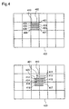
- Fig. 4 is a schematic diagram for explaining the field motion compensation mode.
- An image 422 is a target image to be decoded.
- An image 423 is a reference image to be referred for generating a predictive signal.
- a block 400 is a target block to be reproduced.
- Predictive values of picture elements on lines 401 to 408 are to be calculated.
- MV0_f1 and MV0_f2 represent motion vectors of the odd-numbered field and the even-numbered field, respectively.
- the coordinate values of the picture elements on the lines 401, 403, 405, and 407 are added with MV0_f1, while the coordinate values of the picture elements on the lines 402, 404, 406, and 408 are added with MV0_f2.
- the thus-calculated values are the coordinate values of the picture elements in the reference image 423.
- the predictive signals of the lines 401, 403, 405, and 407 are lines 411, 413, 415, and 417, respectively.
- the predictive signals of the lines 402, 404, 406, and 408 are lines 412, 414, 416, and 418, respectively.
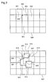
- Fig. 3 is a schematic diagram for describing the overlapped motion compensation mode.
- An image 306 is a target image to be decoded.
- An image 307 is a reference image to be referred for generating a predictive signal.
- a block 300 is a target block to be reproduced. The predictive value of each picture element of the block is to be calculated. Blocks 301, 302, 303, and 304 are adjacent to the block 300.
- overlapped motion compensation is applied only to the frame motion compensation mode. Hence, the frame motion compensation mode will be discussed here.
- MV0, MV1, MV2, MV3, and MV4 are motion vectors of a frame of blocks 300, 301, 302, 303, and 304, respectively.
- the coordinate value of a picture element 305 on the top left end of the target block 300 is added with each motion vector, and each result is regarded as the top left end of each 8x8 block in the reference image 307, thereby producing each predictive block.
- the predictive blocks resulting from adding the motion vectors MV0, MV1, MV2, MV3, and MV4 to the coordinate value of the picture element 305, are blocks 310, 311, 312, 313, and 314.
- the weighted average of each picture element of the blocks is the data of an optimal predictive block to the target block 300.
- the data calculated based on the motion vector MV0 of the target block is multiplied by a weight 4, while the data based on the motion vectors of the adjacent blocks are multiplied by a weight 1, and they are averaged by 8.
- weights other than these values are possible. Rather than the entire blocks 311, 312, 313, and 314, part of them may be used for calculating the average.; for example, half each adjacent block to the target block may be used for average.
- the adjacent block although described is the case that four adjacent blocks are used for average, only left and top adjacent blocks may be used for average, or only a left adjacent block may be used for average, depending on situations.
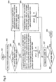
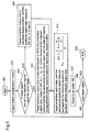
- Fig. 2 is a flowchart of the method of generating a predictive image in the first embodiment.
- information about motion compensation modes i.e., information about a frame motion compensation mode or field motion compensation mode, of a target block to be decoded (hereinafter referred to as a target block)
- a target block a target block to be decoded
- step 203 the mode of an adjacent region to be overlapped (hereinafter referred to as an adjacent block) is compared to that of the target block. For example, as shown in Fig.
- the above-calculated optimal predictive region data is output to the adder 106 in step 207.
- step 208 it is decided whether a current target region is a last target region or not. Until the last target region, the process returns to step 202, and the above operation is repeated to produce optimal predictive region data.
- the first predictive region i.e., the predictive region data to the adjacent region
- the first predictive region data and the target predictive region data calculated using the motion vector of the target region are averaged to obtain optimal predictive region data.
- Blocks in a target region and the adjacent regions having the same motion compensation mode as the target region that is, only blocks having the same frame motion compensation mode, or only blocks having the same field motion compensation mode, are overlapped and averaged.
- the overlapped motion compensation to the interlaced image does not introduce a high-frequency component to a static region, that is, it is not the case that because the target block is in the frame motion compensation mode while an adjacent block is in the field motion compensation mode, and a predictive data calculated based on the motion vector of the adjacent block has a high-frequency component between scanning lines, a high-frequency component is introduced to a predictive signal of a target block due to overlapped motion compensation.
- the temporal resolution of a region having a large motion is not reduced, that is, it is not the case that because the target block is in the field motion compensation mode while an adjacent block is in the frame motion compensation mode, the average in the overlapped motion compensation reduces the temporal resolution of a predictive signal, and blurs the motion in the region having a large motion.
- Fig. 5 is a flowchart showing a method of generating a predictive image by an image predictive decoding method in accordance with a second embodiment which is a variation of the first embodiment.
- the overlapped motion compensation is performed in the following way.
- the predictive region data to the adjacent regions are calculated as first predictive region data, based on the motion vectors of the adjacent regions.
- the predictive region data to the adjacent regions are calculated as second predictive region data, based on the motion vectors of the target region. Thereafter, target predictive region data, and the first and second predictive regions, are averaged to obtain optimal predictive region data.
- overlapped motion compensation is performed in the following way. For adjacent regions having the same motion compensation mode as a target region, first predictive region data are calculated based on the motion vectors of the adjacent regions. For adjacent regions having a motion compensation mode different from that of a target region, second predictive region data are calculated based on the motion vectors of the target region. Thereafter, target predictive region data, and the first and second predictive region are averaged to obtain optimal predictive region data.
- Fig. 6 is a flowchart showing a method of generating a predictive image in an image predictive decoding method in accordance with a third embodiment.
- overlapped motion compensation is performed to a target region and adjacent regions when they both are in a field predictive mode.
- step 602 information about the motion compensation mode of a target block, i.e., the frame motion compensation mode or the field motion compensation mode, is input.
- step 603 the motion compensation modes of the target block and the adjacent blocks are compared with each other.
- step 604 optimal predictive region data is generated by the same method as in step 206 of Fig. 2 or steps 510 and 511 of Fig.5. Thereafter, the optimal predictive region data is output to the adder 106 in step 610.
- step 605 it is decided whether the target block and the adjacent blocks both are in the field predictive mode or not. If not, in step 606, target predictive region data is calculated based on the motion vector MV0 of the target block, and first predictive region is calculated based on the motion vector MV1 for the adjacent region.
- step 607 the target predictive region data and the first predictive region data are averaged to produce optimal predictive region data.
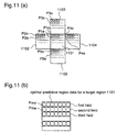
- step 609 the target odd field predictive region data P1o and the first odd field predictive region data P2o to P5o are averaged according to the equation (1).
- the target even field predictive region data P1e and the first even field predictive region data P2e to P5e are averaged according to the equation (1).
- the averaged odd and even field data Pmo and Pme are arranged in a frame structure as shown in Fig. 11(b) to generate optimal predictive region data to a target block 1101.
- the optimal predictive region data is, then, output to the adder 106 in step 610.
- step 611 it is decided whether a current target block is the last one or not. Until the last target block, the process returns to step 602, the foregoing operation is repeated, and the optimal predictive region data is generated and output to the adder 106.
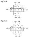
- Fig. 7 is a schematic diagram for explaining the overlapped motion compensation performed to fields in steps 608 and 609.
- reference numeral 706 denotes a target image; 701, 702, 703, and 704, adjacent blocks; and 707, a reference image for calculating predictive data.
- the target block 700 has the field predictive mode. Predictive data calculated based on the odd-numbered field motion vector and the even-number field motion vector are lines 711, 713, 715, and 717, and lines 712, 714, 716, and 718, respectively.
- the adjacent block 701 also has the field predictive mode. Predictive data calculated based on the odd-numbered motion vector and the even-number motion vector are lines 721, 723, 725, and 727, and lines 722, 724, 726, and 728, respectively.
- the line 711, the line 721, and counterparts in the other adjacent blocks are averaged.
- the line 712, the line 722, and counterparts in the other adjacent blocks are averaged.
- the line 713, the line 723, and counterparts in the other adjacent blocks are averaged.
- step 603 it is decided in step 603 whether all the motion compensation modes of a target block and adjacent blocks are the same or not. If not, in step 604, the same process as in step 206 of Fig. 2 is carried out. However, the same process as in steps 510 and 511 of Fig. 5 may be carried out.
- step 603 when all the motion compensation modes of a target block and adjacent blocks are not the same, if the target region and some of the adjacent blocks have the same motion compensation mode, the process equivalent of steps 608 and 609 in Fig. 6 using the average by the equation (2) in step 206 of Fig. Fig. 2, or using the average of the target region data and the first and second predictive region data, in place of the target region data and the first predictive region data, by the equation (3) in steps 510 and 511 of Fig. 5, may be carried out to increase precision of the prediction.
- Fig. 8 is a flowchart showing a method of generating a predictive image in an image predictive decoding method in accordance with a fourth embodiment.
- Steps 802 and 803 are the same as steps 502 and 503 in the above-described second embodiment, and steps 602 and 603 in the third embodiment, respectively.
- the process in step 604 in Fig. 6 described in the third embodiment is carried out in step 804.
- a description will be given of a case where a target block and the adjacent block are in different predictive modes.
- step 805 it is decided whether a target block and at least one of the adjacent blocks are in the frame predictive mode and in the field predictive mode, respectively. If they are, the process goes to step 806.
- two field motion vectors i.e., an odd-numbered field motion vector and an even-numbered field motion vector, are averaged to generate a frame motion vector MV1', to the adjacent regions in the field predictive mode.
- step 807 target predictive region data is calculated based on the motion vector MV0 of the target block, while first predictive region data is calculated based on the averaged frame motion vector MV1' of the adjacent block. Thereafter, the target predictive region data and the first predictive region data are averaged to generate optimal predictive region data in step 808.
- the optimal predictive region data is output to the adder 106 in step 809.
- step 810 first and second field motion vectors of the adjacent block are generated from the first and second field motion vectors of the target block (MV0_f1 and MV0_f2), and the frame motion vector of the adjacent block (MV1).
- step 812 the target odd field predictive region data and the first odd field predictive region data (i), and the target even field predictive region data and the first even field predictive region data (i) each are averaged by the equation (1).
- the averaged odd and even field data are arranged in a frame structure to produce optimal predictive region data, just as shown in Fig. 12(a).
- a target block when overlapped motion compensation is performed to an interlaced image, if a target block is in the frame predictive mode while the adjacent blocks are in the field predictive mode, assuming that the adjacent block has the frame motion vector, two field motion vectors of the adjacent block are averaged to generate an averaged frame motion vector, just as both the target block and the adjacent block are in the frame predictive mode. If the target block is in the field predictive mode while the adjacent blocks are in the frame predictive mode, assuming that the adjacent block has two field motion vectors, first and second field motion vectors are produced based on the field motion vectors of the target block and the frame motion vector of the adjacent block, just as both the target block and the adjacent block are in the field predictive mode. Subsequently, the predictive regions are overlapped and averaged.
- step 803 even when all of a target region and the adjacent regions are not in the same predictive mode, but the target region and some of the adjacent regions are in the same predictive mode, for the target region and the adjacent region that have the same predictive mode, a process equivalent of steps 810, 811, and 812 in Fig. 8 using the average by the equation (2) in step 206 of Fig. 2, or using the average by the equation (3) in steps 510 and 511 of Fig. 5 may be carried out to improve precision of the prediction.
- Fig. 9 is a flowchart showing a method of generating a predictive image in an image predictive decoding method in accordance with a fifth embodiment.
- step 904 is used in place of step 806 in Fig. 8 of the fourth embodiment.
- the field motion vector of the adjacent block approximating to the frame motion vector of the target block is used. This is shown in steps 901 and 902.
- step 806 in Fig. 8 in the fourth embodiment when a target block is in the frame predictive mode while the adjacent block is in the field predictive mode, the predictive data of the adjacent region is calculated using the field motion vector of the adjacent block which is closer to the frame motion vector of the target block. Therefore, just as in the fourth embodiment, there is provided a solution to the problems that a high-frequency component is introduced to a static region, and that the temporal resolution of a region having a large motion is reduced. Furthermore, higher precision overlapped motion compensation can be performed.
- Fig. 12 is a flowchart showing a method of generating a predictive image in an image predictive decoding method in accordance with a sixth embodiment of this invention.
- step 1202 information about the motion compensation mode of a target block to be decoded, i.e., information on whether the target block is in the frame compensation mode or the field compensation mode, is input.
- step 1203 it is decided whether the target block is in the frame compensation (Fr) mode or not. Thereafter, when the target block is in the Fr mode, 0th predictive data is calculated based on the motion vector of the target block in step 1204.
- step 1203 when in step 1203 the target block is not in the Fr mode, but in the Fi mode, only step 1204a which is the same as step 1204 is performed.
- step 1208a the 0th predictive data is regarded as optimal predictive data.
- step 1209 the optimal predictive data is output.
- Fig. 13 is a block diagram showing an image predictive coding apparatus in accordance with a seventh embodiment of this invention, corresponding to claim 10.
- reference numeral 1301a designates an input terminal to which the digital image signal of each frame is input; 1301, a blocking unit for dividing the input digital image signal into blocks (image space) each having 16x16 pixels as a unit of coding, and outputting image data corresponding to each block; 1300c, a predictive data generator deciding the predictive mode corresponding to the data of a target block of a frame being currently processed, from the blocking unit 1301, generating predictive data (data of a predictive block), and comprising a motion detector 1314 and a motion compensation unit 1315; 1302, a first adder outputting a difference between the data of the target block and the data of the predictive block, as residual block data (predictive error signal); 1300a, an encoder compressing an output of the first adder 1302, and outputting compressed residual block data, and comprising a discrete cosine transformer (DCT) 1304 and
- the image signal is divided into blocks by the blocking unit 1301. Thereafter, the data of a target block to be coded is input to the motion detector 1314, while the previous data of a reproduced image (reference image) is input to the motion detector 1314.
- the motion detector 1314 decides the predictive mode of the target block, and, based on the data of a reference image corresponding to a frame being currently processed, outputs motion displacement information indicating a predictive block that has image data having the least error to the image data of the target block, as a motion vector, using such a method as block matching.
- a predictive mode there are the frame predictive mode and the field predictive mode, described above.
- a mode is decided by the same way of MPEG2.
- the decided mode is transmitted along with the motion vector to the variable length encoder 1311 and the motion compensation unit 1315.
- the motion vector is input to the motion compensation unit 1315.
- the motion compensation unit 1315 based on the reference image data corresponding to the current frame, generates the data of a predictive block corresponding to the target block.
- the motion vector is also input to the variable length encoder (VLC) 1311, where the motion vector is converted to variable length codes.
- the codes are output to the output terminal 1301b.
- the first adder calculates a difference between those data as a residual block data.
- the discrete cosine transformer (DCT) 1304 subjects the residual block data to discrete cosine transform (DCT) to transform into frequency components.
- the data is divided into small regions, i.e., blocks consisting of 8x8 pixels.
- the invention is not necessarily restricted to this.
- the frequency components are quantized by the quantizer 1305 to be converted to quantized coefficients.
- the quantized coefficients are output as the data of a compressed block to the variable length encoder (VLC) 1311, where the quantized coefficients are converted to variable length codes.
- VLC variable length encoder
- the variable length codes are output as a coded image signal through the output terminal 1301b.
- the compressed block data is also input to the decoder 1300b where the compressed block data is decompressed. That is, the compressed block data is inversely quantized by the inverse quantizer 1408 to be converted to frequency components. The frequency components are restored to data in the spatial region by the inverse discrete cosine transformer (ICDT) 1309. The data in the spatial region is the residual block data (the data of a decompressed block). The decompressed block data is added with the predictive block data by the second adder 1310. A result of the addition is stored in the frame memory 1313 as the data of a restored block.
- ICDT inverse discrete cosine transformer
- the image predictive coding apparatus of the seventh embodiment can comprise an image predictive coding apparatus corresponding to the image predictive decoding apparatus of each of the first to sixth embodiments, i.e., the image predictive coding apparatus which generates coded signals to be image-predictively decoded by the image predictive decoding apparatus.
- the predictive data generator 1300c performs predictive data generation equivalent to the predictive data generation in the image predictive decoding method of each of the first to sixth embodiments.
- a decoding program for realizing the image predictive decoding apparatus according to the first to sixth embodiments, or an encoding program for realizing the image predictive coding method in the image predictive coding apparatus according to the seventh embodiment is recorded in a data storage medium, such as a floppy disk.
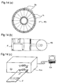
- Figs. 14(a) to 14(c) are diagrams for describing a case where a computer system carries out the image predictive decoding in accordance with the first to sixth embodiments, using a floppy disk storing the decoding program, or the image predictive coding in accordance with the seventh embodiment, using a floppy disk storing the coding program.
- Fig. 14(b) shows a front view of an outside appearance, a section view, and a disk of the floppy disk of a sixth embodiment of this invention.
- Fig. 14(a) shows an example of physical format of the disk that is the core of the storage medium.
- the disk FD is contained in a jacket F.
- On the surface of the disk a plurality of tracks Tr are formed.
- the tracks are concentric circles arranged from an outer circumstance to an inner circumstance.
- Each track is divided into 16 pieces of sectors Se around the center. Accordingly, in a floppy disk storing the program, the data of the program are recorded in an allocated region of the disk FD.
- Fig. 14(c) shows a system for recording and reproducing the program on the disk FD.
- a computer system Cs When the program is recorded on the floppy disk, a computer system Cs writes the program data on the floppy disk via a floppy disk drive.
- the image predictive decoding method is implemented in the computer system by means of a program stored in the floppy disk, the program is read out from the floppy disk via the floppy disk drive, and transmitted to the computer system.
- a floppy disk is used as a data storage medium
- an optical disk can be similarly used.
- a storage medium is not restricted to this.
- Something that can record a program, such as an IC card and a ROM cassette, can be similarly applicable within the scope of this invention.
Landscapes
- Engineering & Computer Science (AREA)
- Multimedia (AREA)
- Signal Processing (AREA)
- Compression Or Coding Systems Of Tv Signals (AREA)
Abstract
Description
Claims (12)
- An image predictive decoding method includinga decoding method in which when decoding compressively coded image data resulting from predicting the data of a predictive region to a target region, using information about a plurality of motion compensation modes, and a plurality of motion vectors corresponding to the plurality of motion compensation modes, and performing , for a target region to be decoded, target predictive region data calculated based on the motion vector of the target region, and adjacent predictive region data calculated based on the motion vector of at least one adjacent region to the target region, are weightedly averaged to produce optimal predictive region data to the target region,said image predictive decoding method calculating the adjacent predictive region data, which is calculated based on the motion vector of at least one adjacent region to the target region, based only on the motion vector of the adjacent region having the same motion compensation mode as the target region, to produce the optimal predictive region data.
- An image predictive decoding method includinga decoding method in which when decoding compressively coded image data including information about a plurality of motion compensation modes, and a plurality of motion vectors corresponding to the plurality of motion compensation modes, for a target region to be decoded, target predictive region data calculated based on the motion vector of the target region, and adjacent predictive region data calculated based on the motion vector of at least one adjacent region to the target region, are weightedly averaged to produce optimal predictive region data to the target region,said image predictive decoding method calculating the adjacent predictive region data, which is calculated based on the motion vector of at least one adjacent region to the target region, based on the motion vector of the adjacent region when the adjacent region has the same motion compensation as the target region, or based on the motion vector of the target region when the adjacent region has a motion compensation mode different from that of the target region, to produce the optimal predictive region data.
- The image predictive decoding method of any of claim 1 and claim 2 includes, as the motion compensation mode,a frame motion compensation mode in which the data of the even-numbered field and odd-numbered field of a predictive region are calculated based on the same motion vector, anda field motion compensation mode in which the data of the even-numbered field of a predictive region are calculated based on a first field motion vector, and the data of the odd-numbered field of the predictive region is calculated based on a second field motion vector.
- An image predictive decoding method includinga decoding method in which when decoding compressively coded image data resulting from predicting predictive region data to a target region, using information about a frame motion compensation mode in which the data of the even-numbered field and odd-numbered field of the predictive region are calculated based on the same motion vector, information about a field motion compensation mode in which the data of the even-numbered field of the predictive region is calculated based on a first field motion vector, and the data of the odd-numbered field of the predictive region is calculated based on a second field motion vector, and motion vectors corresponding to the plurality of motion compensation modes, and performing coding , for a target region to be decoded, target predictive region data calculated based on the motion vector of the target region, and adjacent predictive region data calculated based on the motion vector of at least one adjacent region to the target region, are weightedly averaged to produce optimal predictive region data to the target region,said image predictive decoding method, when the motion compensation modes of the target region and the adjacent region are the field motion compensation modes, calculating the data of an odd-numbered field of target predictive region based on the motion vector of the target region, the data of an even-numbered field of target predictive region based on the motion vector of the target region, the data of a first odd-numbered field of predictive region based on the motion vector of the adjacent region, the data of an even-numbered field of predictive region based on the motion vector of the adjacent region, weightedly averaging the data of an odd-numbered field of target predictive region and the data of a first odd-numbered field of predictive region, and the data of an even-numbered field of target predictive region and the data of a first even-numbered field of predictive region, to produce averaged odd-numbered field data and averaged even-numbered field data, respectively, and arranging the averaged odd-numbered field data and the averaged even-numbered field data in a frame structure, to produce optimal predictive region data.
- An image predictive decoding method includinga decoding method in which when decoding compressively coded image data resulting from predicting predictive region data to a target region, using information about a frame motion compensation mode in which the data of the even-numbered field and odd-numbered field of the predictive region are calculated based on the same motion vector, information about a field motion compensation mode in which the data of the even-numbered field of the predictive region is calculated based on a first field motion vector, and the data of the odd-numbered field of the predictive region is calculated based on a second field motion vector, and motion vectors corresponding to the plurality of motion compensation modes, and performing coding , for a target region to be decoded, target predictive region data calculated based on the motion vector of the target region, and adjacent predictive region data calculated based on the motion vector of at least one adjacent region to the target region, are weightedly averaged to produce optimal predictive region data to the target region,said image predictive decoding method, when the target region is in the frame motion compensation mode while the adjacent region is in the field motion compensation, calculating the adjacent predictive region data, which is calculated based on the motion vector of at least one adjacent region to the target region, based on an averaged frame motion vector of the adjacent region resulting from averaging the first field motion vector of the adjacent region and the second field motion vector of the adjacent region.
- An image predictive decoding method includinga decoding method in which when decoding compressively coded image data resulting from predicting predictive region data to a target region, using information about a frame motion compensation mode in which the data of the even-numbered field and odd-numbered field of the predictive region are calculated based on the same motion vector, information about a field motion compensation mode in which the data of the even-numbered field of the predictive region are calculated based on a first field motion vector, and the data of the odd-numbered field of the predictive region are calculated based on a second field motion vector, and motion vectors corresponding to the plurality of motion compensation modes, and performing coding , for a target region to be decoded, target predictive region data calculated based on the motion vector of the target region, and adjacent predictive region data calculated based on the motion vector of at least one adjacent region to the target region, are weightedly averaged to produce optimal predictive region data to the target region,said image predictive decoding method, when the target region is in the frame motion compensation mode while the adjacent region is in the field motion compensation, calculating the adjacent predictive region data, which is calculated based on the motion vector of at least one adjacent region to the target region, based on one of the first field motion vector of the adjacent region and the second field motion vector of the adjacent region, which has the smaller difference from the motion vector of the target region.
- An image predictive decoding method includinga decoding method in which when decoding compressively coded image data resulting from predicting predictive region data to a target region, using information about a frame motion compensation mode in which the data of the even-numbered field and odd-numbered field of the predictive region are calculated based on the same motion vector, information about a field motion compensation mode in which the predictive data of the even-numbered field of the predictive region is calculated based on a first field motion vector, and the predictive data of the odd-numbered field of the predictive region is calculated based on a second field motion vector, and motion vectors corresponding to the plurality of motion compensation modes, and performing coding , for a target region to be decoded, target predictive region data calculated based on the motion vector of the target region, and adjacent predictive region data calculated based on the motion vector of at least one adjacent region to the target region, are weightedly averaged to produce optimal predictive region data to the target region,said image predictive decoding method, when the target region is in the field motion compensation mode while the adjacent region is in the frame motion compensation, calculating a second field motion vector of the adjacent region, based on a first field motion vector of the target region, a second field motion vector of the target region, and a first field motion vector of the adjacent region equal to the frame motion vector of the adjacent region in assuming that the adjacent region has the information about a field motion compensation mode in which the predictive data of the even-numbered field of the predictive region is calculated based on a first field motion vector, and the predictive data of the odd-numbered field of the predictive region is calculated based on a second field motion vector, and producing the adjacent predictive region data using the first- and second field motion vectors of the adjacent region.
- An image predictive decoding method includinga decoding method in which when decoding compressively coded image data resulting from predicting the data of a predictive region to a target region, using information about a plurality of motion compensation modes, and a plurality of motion vectors corresponding to the plurality of motion compensation modes, and performing , for a target region to be decoded, target predictive region data calculated based on the motion vector of the target region, and adjacent predictive region data calculated based on the motion vector of at least one adjacent region to the target region, are weightedly averaged to produce optimal predictive region data to the target region,said image predictive decoding method calculating the adjacent predictive region data, when the target region is in the frame motion compensation mode, weightedly averaging the target predictive region data and the adjacent predictive region data, to produce the optimal predictive region data to the target region,while when the target region is in the field motion compensation mode, the optimal predictive region data to the target region is calculated based only on the motion vector of the target region.
- The image predictive decoding method of claim 8 wherein when the target region is in the frame motion compensation mode, optimal predictive region data to the target region is calculated in a way in which it is decided whether each adjacent region to the target region is in the field motion compensation mode, or not, and when the adjacent region is in the field motion compensation mode, the first and second motion vectors of the adjacent region are averaged, predictive region data to the adjacent region is calculated based on the averaged field motion vector of the adjacent region, and the target predictive region data and all of the adjacent predictive region data are averaged to produce the optimal predictive data to the target region.
- An image predictive decoding apparatus comprising:a frame memory;an input unit for receiving compressively coded image data including information about a plurality of motion compensation modes, and a plurality of motion vectors corresponding to the plurality of motion compensation modes;a data analyzer for analyzing the compressively coded image data, and outputting at least the information about the plurality of motion compensation modes, the plurality of motion vectors corresponding to the plurality of motion compensation modes, and image transform coefficients;a decoder for restoring the image transform coefficients with a prescribed method to a decompressed difference image;a predictive image generator for generating an optimal predictive image based on a reference image stored said frame memory; andan adder for adding the decompressed difference image and the optimal predictive image to produce a reproduced image, outputting the same, and storing the same in said frame memory,said predictive image generator producing optimal predictive region data using the image predictive decoding method of any of claim 1 to claim 9.
- An image predictive coding apparatus comprising:a frame memory;an output unit;an input unit for receiving a digital image signal of each frame;a predictive data generator for generating the data of a predictive block based on a reference image stored in said frame memory;a first adder for outputting difference data between the data of a target block and the data of the predictive block, as the data of a residual block;an encoder for compressing the data of the residual block and, outputting the compressed data of the residual block;a variable length encoder for subjecting the compressed data of the residual block to variable length coding, and outputting the resulting coded signal through said output unit;a decoder for decompressing the compressed data of the residual block, and outputting the decompressed data of the residual block; anda second adder for adding the decompressed data of the residual block to the data of the predictive block, outputting the data of a resulting reproduced block, and storing the data of the reproduced data in said frame memory,said predictive data generator performing predictive data production corresponding to the optimal predictive region data production in the image predictive decoding method of any of claim 1 to claim 9.
- A data storage medium storing a program for performing the image predictive decoding method of any of claim 1 to claim 9, using a computer.
Applications Claiming Priority (3)
| Application Number | Priority Date | Filing Date | Title |
|---|---|---|---|
| JP17976197 | 1997-07-04 | ||
| JP179761/97 | 1997-07-04 | ||
| JP17976197 | 1997-07-04 |
Publications (2)
| Publication Number | Publication Date |
|---|---|
| EP0889653A2 true EP0889653A2 (en) | 1999-01-07 |
| EP0889653A3 EP0889653A3 (en) | 2001-03-07 |
Family
ID=16071430
Family Applications (1)
| Application Number | Title | Priority Date | Filing Date |
|---|---|---|---|
| EP98112463A Withdrawn EP0889653A3 (en) | 1997-07-04 | 1998-07-06 | Image predictive decoding method using a plurality of motion compensation modes and motion information from adjacent regions |
Country Status (4)
| Country | Link |
|---|---|
| US (1) | US6359929B1 (en) |
| EP (1) | EP0889653A3 (en) |
| KR (1) | KR100307340B1 (en) |
| CN (1) | CN1212562A (en) |
Cited By (3)
| Publication number | Priority date | Publication date | Assignee | Title |
|---|---|---|---|---|
| EP2023639A4 (en) * | 2006-04-28 | 2010-09-01 | Ntt Docomo Inc | IMAGE PREDICTIVE ENCODING DEVICE, IMAGE PREDICTIVE ENCODING METHOD, IMAGE PREDICTIVE ENCODING PROGRAM, IMAGE PREDICTIVE DECODING DEVICE, IMAGE PREDICTIVE DECODING METHOD, AND PREDICTIVE IMAGE DECODING PROGRAM |
| EP2413605A4 (en) * | 2009-03-23 | 2013-07-17 | Ntt Docomo Inc | IMAGE PREDICTIVE ENCODING DEVICE, IMAGE PREDICTIVE ENCODING METHOD, IMAGE PREDICTIVE ENCODING PROGRAM, IMAGE PREDICTIVE DECODING DEVICE, IMAGE PREDICTIVE DECODING METHOD, AND IMAGE PREDICTIVE DECODING PROGRAM |
| US9497480B2 (en) | 2010-07-20 | 2016-11-15 | Ntt Docomo, Inc. | Image prediction encoding/decoding system |
Families Citing this family (80)
| Publication number | Priority date | Publication date | Assignee | Title |
|---|---|---|---|---|
| US6499060B1 (en) * | 1999-03-12 | 2002-12-24 | Microsoft Corporation | Media coding for loss recovery with remotely predicted data units |
| US6829303B1 (en) * | 1999-11-17 | 2004-12-07 | Hitachi America, Ltd. | Methods and apparatus for decoding images using dedicated hardware circuitry and a programmable processor |
| US6473460B1 (en) * | 2000-03-31 | 2002-10-29 | Matsushita Electric Industrial Co., Ltd. | Method and apparatus for calculating motion vectors |
| JP2005505212A (en) * | 2001-10-03 | 2005-02-17 | コーニンクレッカ フィリップス エレクトロニクス エヌ ヴィ | Static region detection |
| DE10225434B4 (en) * | 2002-06-07 | 2004-12-30 | Siemens Ag | Video coding method and apparatus |
| EP1422928A3 (en) * | 2002-11-22 | 2009-03-11 | Panasonic Corporation | Motion compensated interpolation of digital video signals |
| JP3504256B1 (en) * | 2002-12-10 | 2004-03-08 | 株式会社エヌ・ティ・ティ・ドコモ | Video encoding method, video decoding method, video encoding device, and video decoding device |
| JP2004213641A (en) * | 2002-12-20 | 2004-07-29 | Sony Computer Entertainment Inc | Image processor, image processing method, information processor, information processing system, semiconductor device and computer program |
| US8824553B2 (en) | 2003-05-12 | 2014-09-02 | Google Inc. | Video compression method |
| US7453940B2 (en) * | 2003-07-15 | 2008-11-18 | Lsi Corporation | High quality, low memory bandwidth motion estimation processor |
| US7567617B2 (en) * | 2003-09-07 | 2009-07-28 | Microsoft Corporation | Predicting motion vectors for fields of forward-predicted interlaced video frames |
| US20070242747A1 (en) * | 2004-11-29 | 2007-10-18 | Park Seung W | Method and apparatus for encoding/decoding a first frame sequence layer based on a second frame sequence layer |
| US20070280354A1 (en) * | 2004-11-29 | 2007-12-06 | Park Seung W | Method and apparatus for encoding/decoding a first frame sequence layer based on a second frame sequence layer |
| US20080008241A1 (en) * | 2004-11-29 | 2008-01-10 | Park Seung W | Method and apparatus for encoding/decoding a first frame sequence layer based on a second frame sequence layer |
| US20070223573A1 (en) * | 2004-11-29 | 2007-09-27 | Park Seung W | Method and apparatus for encoding/decoding a first frame sequence layer based on a second frame sequence layer |
| US8634413B2 (en) | 2004-12-30 | 2014-01-21 | Microsoft Corporation | Use of frame caching to improve packet loss recovery |
| JP2006270676A (en) * | 2005-03-25 | 2006-10-05 | Fujitsu Ltd | Panorama image generation program, panorama image generation apparatus, and panorama image generation method |
| JP2007043651A (en) * | 2005-07-05 | 2007-02-15 | Ntt Docomo Inc | Moving picture coding apparatus, moving picture coding method, moving picture coding program, moving picture decoding apparatus, moving picture decoding method, and moving picture decoding program |
| KR100678911B1 (en) * | 2005-07-21 | 2007-02-05 | 삼성전자주식회사 | Method and apparatus for encoding and decoding video signals by extending the application of directional intra prediction |
| KR100728011B1 (en) * | 2005-11-09 | 2007-06-14 | 삼성전자주식회사 | An image encoding and decoding apparatus, a method thereof, and a recording medium having recorded thereon a program for performing the same. |
| KR101256548B1 (en) * | 2005-12-30 | 2013-04-19 | 삼성전자주식회사 | Image encoding and decoding apparatuses and methods |
| JP2010509799A (en) * | 2006-11-03 | 2010-03-25 | サムスン エレクトロニクス カンパニー リミテッド | Video predictive encoding method and apparatus, and decoding method and apparatus thereof |
| CN101543036B (en) * | 2006-11-24 | 2011-10-26 | 日本电气株式会社 | Coding and decoding device, coding and decoding method |
| CN101231850B (en) * | 2007-01-23 | 2012-02-29 | 华为技术有限公司 | Encoding/decoding device and method |
| US8385404B2 (en) | 2008-09-11 | 2013-02-26 | Google Inc. | System and method for video encoding using constructed reference frame |
| US8326075B2 (en) | 2008-09-11 | 2012-12-04 | Google Inc. | System and method for video encoding using adaptive loop filter |
| US8325796B2 (en) | 2008-09-11 | 2012-12-04 | Google Inc. | System and method for video coding using adaptive segmentation |
| KR101543298B1 (en) * | 2008-10-13 | 2015-08-10 | 에스케이 텔레콤주식회사 | / Video encoding/decoding apparatus and Variable OBMC apparatus and method |
| KR101512643B1 (en) * | 2008-10-22 | 2015-04-16 | 에스케이 텔레콤주식회사 | Video encoding apparatus, apparatus and method for two-dimensional re-arrangement of video signal for the same, and recording medium therefor |
| US9532059B2 (en) | 2010-10-05 | 2016-12-27 | Google Technology Holdings LLC | Method and apparatus for spatial scalability for video coding |
| US8611415B1 (en) | 2010-11-15 | 2013-12-17 | Google Inc. | System and method for coding using improved motion estimation |
| US8891626B1 (en) | 2011-04-05 | 2014-11-18 | Google Inc. | Center of motion for encoding motion fields |
| US8693547B2 (en) | 2011-04-06 | 2014-04-08 | Google Inc. | Apparatus and method for coding using motion vector segmentation |
| US8638854B1 (en) | 2011-04-07 | 2014-01-28 | Google Inc. | Apparatus and method for creating an alternate reference frame for video compression using maximal differences |
| US8781004B1 (en) | 2011-04-07 | 2014-07-15 | Google Inc. | System and method for encoding video using variable loop filter |
| US8780971B1 (en) | 2011-04-07 | 2014-07-15 | Google, Inc. | System and method of encoding using selectable loop filters |
| US9154799B2 (en) | 2011-04-07 | 2015-10-06 | Google Inc. | Encoding and decoding motion via image segmentation |
| US8780996B2 (en) | 2011-04-07 | 2014-07-15 | Google, Inc. | System and method for encoding and decoding video data |
| US8804819B1 (en) | 2011-04-19 | 2014-08-12 | Google Inc. | Method and apparatus for encoding video using data frequency |
| US8705620B1 (en) | 2011-04-28 | 2014-04-22 | Google Inc. | Method and apparatus for encoding anchor frame by encoding features using layers |
| US9749638B1 (en) | 2011-04-28 | 2017-08-29 | Google Inc. | Method and apparatus for encoding video with dynamic quality improvement |
| US8989256B2 (en) | 2011-05-25 | 2015-03-24 | Google Inc. | Method and apparatus for using segmentation-based coding of prediction information |
| EP2727357A1 (en) | 2011-07-01 | 2014-05-07 | Motorola Mobility LLC | Motion vector prediction design simplification |
| US8885706B2 (en) | 2011-09-16 | 2014-11-11 | Google Inc. | Apparatus and methodology for a video codec system with noise reduction capability |
| US9185428B2 (en) | 2011-11-04 | 2015-11-10 | Google Technology Holdings LLC | Motion vector scaling for non-uniform motion vector grid |
| US9247257B1 (en) | 2011-11-30 | 2016-01-26 | Google Inc. | Segmentation based entropy encoding and decoding |
| US9014265B1 (en) | 2011-12-29 | 2015-04-21 | Google Inc. | Video coding using edge detection and block partitioning for intra prediction |
| US8908767B1 (en) | 2012-02-09 | 2014-12-09 | Google Inc. | Temporal motion vector prediction |
| US9262670B2 (en) | 2012-02-10 | 2016-02-16 | Google Inc. | Adaptive region of interest |
| US9094681B1 (en) | 2012-02-28 | 2015-07-28 | Google Inc. | Adaptive segmentation |
| US9131073B1 (en) | 2012-03-02 | 2015-09-08 | Google Inc. | Motion estimation aided noise reduction |
| EP2842337B1 (en) | 2012-04-23 | 2019-03-13 | Google LLC | Managing multi-reference picture buffers for video data coding |
| US9609341B1 (en) | 2012-04-23 | 2017-03-28 | Google Inc. | Video data encoding and decoding using reference picture lists |
| US9172970B1 (en) | 2012-05-29 | 2015-10-27 | Google Inc. | Inter frame candidate selection for a video encoder |
| US9014266B1 (en) | 2012-06-05 | 2015-04-21 | Google Inc. | Decimated sliding windows for multi-reference prediction in video coding |
| US11317101B2 (en) | 2012-06-12 | 2022-04-26 | Google Inc. | Inter frame candidate selection for a video encoder |
| US9344729B1 (en) | 2012-07-11 | 2016-05-17 | Google Inc. | Selective prediction signal filtering |
| US9332276B1 (en) | 2012-08-09 | 2016-05-03 | Google Inc. | Variable-sized super block based direct prediction mode |
| US9380298B1 (en) | 2012-08-10 | 2016-06-28 | Google Inc. | Object-based intra-prediction |
| US9288484B1 (en) | 2012-08-30 | 2016-03-15 | Google Inc. | Sparse coding dictionary priming |
| US9369732B2 (en) | 2012-10-08 | 2016-06-14 | Google Inc. | Lossless intra-prediction video coding |
| US9503746B2 (en) | 2012-10-08 | 2016-11-22 | Google Inc. | Determine reference motion vectors |
| US9210432B2 (en) | 2012-10-08 | 2015-12-08 | Google Inc. | Lossless inter-frame video coding |
| US9485515B2 (en) | 2013-08-23 | 2016-11-01 | Google Inc. | Video coding using reference motion vectors |
| US9756346B2 (en) | 2012-10-08 | 2017-09-05 | Google Inc. | Edge-selective intra coding |
| US9407915B2 (en) | 2012-10-08 | 2016-08-02 | Google Inc. | Lossless video coding with sub-frame level optimal quantization values |
| US9225979B1 (en) | 2013-01-30 | 2015-12-29 | Google Inc. | Remote access encoding |
| US9210424B1 (en) | 2013-02-28 | 2015-12-08 | Google Inc. | Adaptive prediction block size in video coding |
| US9300906B2 (en) | 2013-03-29 | 2016-03-29 | Google Inc. | Pull frame interpolation |
| US9756331B1 (en) | 2013-06-17 | 2017-09-05 | Google Inc. | Advance coded reference prediction |
| US9313493B1 (en) | 2013-06-27 | 2016-04-12 | Google Inc. | Advanced motion estimation |
| JP6222854B2 (en) * | 2013-10-23 | 2017-11-01 | 株式会社K−Will | Video inspection method and audio inspection method |
| US10444304B2 (en) * | 2014-03-26 | 2019-10-15 | General Electric Company | Particle event recordation |
| US9392272B1 (en) | 2014-06-02 | 2016-07-12 | Google Inc. | Video coding using adaptive source variance based partitioning |
| US9578324B1 (en) | 2014-06-27 | 2017-02-21 | Google Inc. | Video coding using statistical-based spatially differentiated partitioning |
| US9286653B2 (en) | 2014-08-06 | 2016-03-15 | Google Inc. | System and method for increasing the bit depth of images |
| US9153017B1 (en) | 2014-08-15 | 2015-10-06 | Google Inc. | System and method for optimized chroma subsampling |
| US10102613B2 (en) | 2014-09-25 | 2018-10-16 | Google Llc | Frequency-domain denoising |
| US9807416B2 (en) | 2015-09-21 | 2017-10-31 | Google Inc. | Low-latency two-pass video coding |
| JP6834937B2 (en) * | 2017-12-27 | 2021-02-24 | 株式会社Jvcケンウッド | Projector system and camera evaluation system |
Family Cites Families (8)
| Publication number | Priority date | Publication date | Assignee | Title |
|---|---|---|---|---|
| US5210605A (en) | 1991-06-11 | 1993-05-11 | Trustees Of Princeton University | Method and apparatus for determining motion vectors for image sequences |
| WO1995003674A1 (en) * | 1993-07-19 | 1995-02-02 | British Telecommunications Public Limited Company | Detecting errors in video images |
| US5812197A (en) * | 1995-05-08 | 1998-09-22 | Thomson Consumer Electronics, Inc. | System using data correlation for predictive encoding of video image data subject to luminance gradients and motion |
| US5687097A (en) | 1995-07-13 | 1997-11-11 | Zapex Technologies, Inc. | Method and apparatus for efficiently determining a frame motion vector in a video encoder |
| US5745183A (en) * | 1995-08-25 | 1998-04-28 | Thomson Consumer Electronics, Inc. | Image motion estimation system which derives candidate block from interpolated motion vectors |
| JP3297293B2 (en) * | 1996-03-07 | 2002-07-02 | 三菱電機株式会社 | Video decoding method and video decoding device |
| US5905542A (en) * | 1996-12-04 | 1999-05-18 | C-Cube Microsystems, Inc. | Simplified dual prime video motion estimation |
| US6115070A (en) * | 1997-06-12 | 2000-09-05 | International Business Machines Corporation | System and method for DCT domain inverse motion compensation using shared information |
-
1998
- 1998-07-02 US US09/109,896 patent/US6359929B1/en not_active Expired - Fee Related
- 1998-07-03 CN CN98117411A patent/CN1212562A/en active Pending
- 1998-07-04 KR KR1019980027016A patent/KR100307340B1/en not_active Expired - Fee Related
- 1998-07-06 EP EP98112463A patent/EP0889653A3/en not_active Withdrawn
Cited By (20)
| Publication number | Priority date | Publication date | Assignee | Title |
|---|---|---|---|---|
| US8634670B2 (en) | 2006-04-28 | 2014-01-21 | Ntt Docomo, Inc. | Method, apparatus and program for efficient generation of prediction signals |
| EP2323405A1 (en) * | 2006-04-28 | 2011-05-18 | NTT DoCoMo, Inc. | Image predictive coding and decoding device, method and program |
| EP2453657A1 (en) * | 2006-04-28 | 2012-05-16 | NTT DoCoMo, Inc. | Image predictive decoding device |
| US8326063B2 (en) | 2006-04-28 | 2012-12-04 | Ntt Docomo, Inc. | Method, apparatus and program for efficient generation of prediction signals |
| EP2595381A3 (en) * | 2006-04-28 | 2013-11-13 | NTT DoCoMo, Inc. | Image predictive coding device, image predictive coding method, image predictive coding program, image predictive decoding device, image predictive decoding method and image predictive decoding program |
| EP2023639A4 (en) * | 2006-04-28 | 2010-09-01 | Ntt Docomo Inc | IMAGE PREDICTIVE ENCODING DEVICE, IMAGE PREDICTIVE ENCODING METHOD, IMAGE PREDICTIVE ENCODING PROGRAM, IMAGE PREDICTIVE DECODING DEVICE, IMAGE PREDICTIVE DECODING METHOD, AND PREDICTIVE IMAGE DECODING PROGRAM |
| EP2413605A4 (en) * | 2009-03-23 | 2013-07-17 | Ntt Docomo Inc | IMAGE PREDICTIVE ENCODING DEVICE, IMAGE PREDICTIVE ENCODING METHOD, IMAGE PREDICTIVE ENCODING PROGRAM, IMAGE PREDICTIVE DECODING DEVICE, IMAGE PREDICTIVE DECODING METHOD, AND IMAGE PREDICTIVE DECODING PROGRAM |
| US10284846B2 (en) | 2009-03-23 | 2019-05-07 | Ntt Docomo, Inc. | Image predictive encoding and decoding device |
| EP2988500A1 (en) * | 2009-03-23 | 2016-02-24 | Ntt Docomo, Inc. | Image predictive encoding device, image predictive encoding method, image predictive encoding program, image predictive decoding device, image predictive decoding method, and image predictive decoding program |
| US10284847B2 (en) | 2009-03-23 | 2019-05-07 | Ntt Docomo, Inc. | Image predictive encoding and decoding device |
| US9549186B2 (en) | 2009-03-23 | 2017-01-17 | Ntt Docomo, Inc. | Image predictive encoding and decoding device |
| US10284848B2 (en) | 2009-03-23 | 2019-05-07 | Ntt Docomo, Inc. | Image predictive encoding and decoding device |
| US10063855B2 (en) | 2009-03-23 | 2018-08-28 | Ntt Docomo, Inc. | Image predictive encoding and decoding device |
| US9794592B2 (en) | 2010-07-20 | 2017-10-17 | Ntt Docomo, Inc. | Image prediction encoding/decoding system |
| US10225580B2 (en) | 2010-07-20 | 2019-03-05 | Ntt Docomo, Inc. | Image prediction encoding/decoding system |
| US10230987B2 (en) | 2010-07-20 | 2019-03-12 | Ntt Docomo, Inc. | Image prediction encoding/decoding system |
| US10063888B1 (en) | 2010-07-20 | 2018-08-28 | Ntt Docomo, Inc. | Image prediction encoding/decoding system |
| US9986261B2 (en) | 2010-07-20 | 2018-05-29 | Ntt Docomo, Inc. | Image prediction encoding/decoding system |
| US9497480B2 (en) | 2010-07-20 | 2016-11-15 | Ntt Docomo, Inc. | Image prediction encoding/decoding system |
| US10542287B2 (en) | 2010-07-20 | 2020-01-21 | Ntt Docomo, Inc. | Image prediction encoding/decoding system |
Also Published As
| Publication number | Publication date |
|---|---|
| KR19990013613A (en) | 1999-02-25 |
| EP0889653A3 (en) | 2001-03-07 |
| KR100307340B1 (en) | 2001-10-19 |
| CN1212562A (en) | 1999-03-31 |
| US6359929B1 (en) | 2002-03-19 |
Similar Documents
| Publication | Publication Date | Title |
|---|---|---|
| US6359929B1 (en) | Image predictive decoding method, image predictive decoding apparatus, image predictive coding apparatus, and data storage medium | |
| JP3593988B2 (en) | Moving picture signal compression apparatus and method | |
| EP0683615B1 (en) | Compression method for interlace moving image signals | |
| CN100415000C (en) | Moving picture decoding method and moving picture decoding device | |
| HK1000752B (en) | Compression method of interlace moving image signals | |
| US6360014B1 (en) | Image decoding method, image decoding apparatus, and data recording medium | |
| JP3417443B2 (en) | Apparatus and method for motion estimation for B picture | |
| US5991445A (en) | Image processing apparatus | |
| US6353683B1 (en) | Method and apparatus of image processing, and data storage media | |
| US20020168008A1 (en) | Method and apparatus for coding moving pictures | |
| BE1007681A3 (en) | Device for transfer of television images and device for receiving it. | |
| JP2924691B2 (en) | Quantization noise reduction method and image data decoding device | |
| US20040013200A1 (en) | Advanced method of coding and decoding motion vector and apparatus therefor | |
| JP3700801B2 (en) | Image coding apparatus and image coding method | |
| JP2006025033A (en) | Image processing apparatus and image processing method | |
| JPH1175193A (en) | Image prediction decoding method, image prediction decoding device, image prediction encoding device, and data storage medium | |
| JP2883592B2 (en) | Moving picture decoding apparatus and moving picture decoding method | |
| KR100657714B1 (en) | Image Data Encoding Method Using 3D Scanning | |
| KR100228684B1 (en) | Method and apparatus for concealing time prediction error based on motion estimation | |
| JPH10164594A (en) | Moving image compression encoding method and apparatus | |
| JPH06284415A (en) | Motion compensated predictive coding and decoding device | |
| HK1000794B (en) | Compression method for interlace moving image signals | |
| KR19980015341A (en) | [0002] IMAGE DECODER HAVING FUNCTIONS FOR RECONSTRUCTING ERROR OF MOTION VECTORS [0003] | |
| JPH1042296A (en) | Moving picture coding apparatus and moving picture coding method | |
| HK1076962B (en) | Moving image decoding method,moving image decoding apparatus |
Legal Events
| Date | Code | Title | Description |
|---|---|---|---|
| PUAI | Public reference made under article 153(3) epc to a published international application that has entered the european phase |
Free format text: ORIGINAL CODE: 0009012 |
|
| AK | Designated contracting states |
Kind code of ref document: A2 Designated state(s): DE ES FR GB IT |
|
| AX | Request for extension of the european patent |
Free format text: AL;LT;LV;MK;RO;SI |
|
| PUAL | Search report despatched |
Free format text: ORIGINAL CODE: 0009013 |
|
| AK | Designated contracting states |
Kind code of ref document: A3 Designated state(s): AT BE CH CY DE DK ES FI FR GB GR IE IT LI LU MC NL PT SE |
|
| AX | Request for extension of the european patent |
Free format text: AL;LT;LV;MK;RO;SI |
|
| 17P | Request for examination filed |
Effective date: 20010410 |
|
| AKX | Designation fees paid |
Free format text: DE ES FR GB IT |
|
| 17Q | First examination report despatched |
Effective date: 20070502 |
|
| STAA | Information on the status of an ep patent application or granted ep patent |
Free format text: STATUS: THE APPLICATION IS DEEMED TO BE WITHDRAWN |
|
| 18D | Application deemed to be withdrawn |
Effective date: 20070913 |