EP0888511B1 - Dichtring für eine rohrverbindung - Google Patents
Dichtring für eine rohrverbindung Download PDFInfo
- Publication number
- EP0888511B1 EP0888511B1 EP97908252A EP97908252A EP0888511B1 EP 0888511 B1 EP0888511 B1 EP 0888511B1 EP 97908252 A EP97908252 A EP 97908252A EP 97908252 A EP97908252 A EP 97908252A EP 0888511 B1 EP0888511 B1 EP 0888511B1
- Authority
- EP
- European Patent Office
- Prior art keywords
- sealing ring
- protective strip
- sliding surface
- slide
- lubricant
- Prior art date
- Legal status (The legal status is an assumption and is not a legal conclusion. Google has not performed a legal analysis and makes no representation as to the accuracy of the status listed.)
- Expired - Lifetime
Links
- 238000007789 sealing Methods 0.000 title claims abstract description 35
- 230000001681 protective effect Effects 0.000 claims abstract description 44
- 239000000314 lubricant Substances 0.000 claims abstract description 27
- 239000000463 material Substances 0.000 claims abstract description 17
- 229920001971 elastomer Polymers 0.000 claims abstract description 7
- 239000000806 elastomer Substances 0.000 claims abstract description 7
- 239000002184 metal Substances 0.000 claims abstract description 5
- 229910052751 metal Inorganic materials 0.000 claims abstract description 5
- 239000004033 plastic Substances 0.000 claims abstract description 5
- 229920003023 plastic Polymers 0.000 claims abstract description 5
- 229910010293 ceramic material Inorganic materials 0.000 claims abstract description 4
- 230000002093 peripheral effect Effects 0.000 claims abstract description 4
- 239000011248 coating agent Substances 0.000 claims description 9
- 238000000576 coating method Methods 0.000 claims description 9
- VYPSYNLAJGMNEJ-UHFFFAOYSA-N silicon dioxide Inorganic materials O=[Si]=O VYPSYNLAJGMNEJ-UHFFFAOYSA-N 0.000 claims description 4
- OKTJSMMVPCPJKN-UHFFFAOYSA-N Carbon Chemical compound [C] OKTJSMMVPCPJKN-UHFFFAOYSA-N 0.000 claims description 3
- 239000010439 graphite Substances 0.000 claims description 3
- 229910002804 graphite Inorganic materials 0.000 claims description 3
- 239000010453 quartz Substances 0.000 claims description 3
- 239000000454 talc Substances 0.000 claims description 3
- 229910052623 talc Inorganic materials 0.000 claims description 3
- 244000144992 flock Species 0.000 claims 1
- 235000012054 meals Nutrition 0.000 claims 1
- 230000008878 coupling Effects 0.000 abstract 1
- 238000010168 coupling process Methods 0.000 abstract 1
- 238000005859 coupling reaction Methods 0.000 abstract 1
- 239000010410 layer Substances 0.000 description 13
- 239000007921 spray Substances 0.000 description 3
- 238000004873 anchoring Methods 0.000 description 2
- 235000013312 flour Nutrition 0.000 description 2
- 150000002739 metals Chemical class 0.000 description 2
- 239000006004 Quartz sand Substances 0.000 description 1
- 239000000654 additive Substances 0.000 description 1
- 239000000853 adhesive Substances 0.000 description 1
- 230000001070 adhesive effect Effects 0.000 description 1
- 239000004566 building material Substances 0.000 description 1
- 235000013339 cereals Nutrition 0.000 description 1
- 235000014113 dietary fatty acids Nutrition 0.000 description 1
- 239000000428 dust Substances 0.000 description 1
- 239000003925 fat Substances 0.000 description 1
- 239000000194 fatty acid Substances 0.000 description 1
- 229930195729 fatty acid Natural products 0.000 description 1
- 150000004665 fatty acids Chemical class 0.000 description 1
- 230000009969 flowable effect Effects 0.000 description 1
- 239000011859 microparticle Substances 0.000 description 1
- 239000000203 mixture Substances 0.000 description 1
- 239000004810 polytetrafluoroethylene Substances 0.000 description 1
- 229920001343 polytetrafluoroethylene Polymers 0.000 description 1
- 230000000284 resting effect Effects 0.000 description 1
- 239000012791 sliding layer Substances 0.000 description 1
- 229920003048 styrene butadiene rubber Polymers 0.000 description 1
- 239000013008 thixotropic agent Substances 0.000 description 1
- 238000004073 vulcanization Methods 0.000 description 1
Images
Classifications
-
- F—MECHANICAL ENGINEERING; LIGHTING; HEATING; WEAPONS; BLASTING
- F16—ENGINEERING ELEMENTS AND UNITS; GENERAL MEASURES FOR PRODUCING AND MAINTAINING EFFECTIVE FUNCTIONING OF MACHINES OR INSTALLATIONS; THERMAL INSULATION IN GENERAL
- F16L—PIPES; JOINTS OR FITTINGS FOR PIPES; SUPPORTS FOR PIPES, CABLES OR PROTECTIVE TUBING; MEANS FOR THERMAL INSULATION IN GENERAL
- F16L21/00—Joints with sleeve or socket
- F16L21/02—Joints with sleeve or socket with elastic sealing rings between pipe and sleeve or between pipe and socket, e.g. with rolling or other prefabricated profiled rings
- F16L21/035—Joints with sleeve or socket with elastic sealing rings between pipe and sleeve or between pipe and socket, e.g. with rolling or other prefabricated profiled rings placed around the spigot end before connection
-
- F—MECHANICAL ENGINEERING; LIGHTING; HEATING; WEAPONS; BLASTING
- F16—ENGINEERING ELEMENTS AND UNITS; GENERAL MEASURES FOR PRODUCING AND MAINTAINING EFFECTIVE FUNCTIONING OF MACHINES OR INSTALLATIONS; THERMAL INSULATION IN GENERAL
- F16L—PIPES; JOINTS OR FITTINGS FOR PIPES; SUPPORTS FOR PIPES, CABLES OR PROTECTIVE TUBING; MEANS FOR THERMAL INSULATION IN GENERAL
- F16L21/00—Joints with sleeve or socket
- F16L21/02—Joints with sleeve or socket with elastic sealing rings between pipe and sleeve or between pipe and socket, e.g. with rolling or other prefabricated profiled rings
- F16L21/03—Joints with sleeve or socket with elastic sealing rings between pipe and sleeve or between pipe and socket, e.g. with rolling or other prefabricated profiled rings placed in the socket before connection
Definitions
- the invention relates to a sealing ring made of an elastomer for a push-in joint to seal the gap between Ends of pipes made of hard material (concrete or other ceramic material, plastic, metal), with a Main torus made of an elastomer with a sliding surface, through which the pipe connection can be made self-centering is, with the main torus of the sealing ring in the Area of the sliding surface with at least one circumferential, easily removable protective strip connected to the Sliding surface initially covers and between its Underside and the sliding surface leaves a cavity, and the sliding surface with one below the protective strip lying lubricant layer is provided.
- a sealing ring of this type is known (US A 4,496,175). Disadvantageous in the known sealing ring is that when tearing of the protective strip, the lubricant partly with the protective strip is removed or the protective strip is torn off difficult, especially when it is at low temperatures has become stiff.
- This problem is solved by adding the sliding layer its side facing the inside of the protective strip is provided with an adhesion-reducing coating or the inside of the protective strip with an adhesion reducing Coating is provided.
- This coating can, for example, from quartz flour, talc, graphite, one Flocking or a fleece pad exist. It is also possible a siliconized layer on the inside of the Protective strip.
- the protective strip usually consists of a one-piece, thin, wing-like element. But it should also cannot be excluded, the protective strip from two to produce wing-like halves, each one-sided a peripheral outer edge of the sliding surface easily are removably attached in this case the lubricant layer through a nozzle with the protective strip open be introduced.
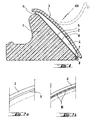
- the sealing ring 100 shown in Figure 1 consists of a Elastomer, especially styrene-butadiene rubber.
- the sealing ring 100 is used to seal the gap between two pipe ends of pipes made of hard material. He will be on top raised.
- the pipe materials include, for example Concrete, other ceramic materials, plastics or metals. In general, however, it should be indicated that sealing rings with corresponding dimensions also for shaft structures individual shaft rings, fittings and the like is suitable, without leaving the scope of the invention.
- Main torus 1 present, on an abutment at the tip end can be connected to the pipe. But it is not excluded that the sealing ring under tension in corresponding Grooves are inserted or by anchoring in the pipe material, preferably on the socket side becomes. It is also not excluded that the main torus 1 designed as a hollow profile or with different fillings is.
- the main torus 1 has a sliding surface 2 on which the End of a tube can be pushed on.
- the sliding surface is provided with a lubricant layer 5 which consists of a known lubricants from a mixture of saponified Metals, fats, fatty acids and inorganic additives.
- the lubricant layer 5 is covered by a protective strip 3 protected, which has been extruded together with the main torus 1 and is made of the same material.
- the protective strip 3 is over a thin material web 6 with the Main torus 1 connected.
- the material web 6 is designed that when the sealing ring is stretched, the on-hook of the sealing ring e.g. to the pointy end, going ahead, partial tears (at 16; see FIG. 2a, 2b) and thus tearing of the protective strip 3 facilitated by the main torus 1.
- the protective strip At its front end is the protective strip with a barb profile 7 provided that in a compatible groove 8 of the Main torus 1 engages or can be engaged.
- This resulting circumferential locking element enables easy removal of the protective strip 3 from the lower half of the main torus, so that it lies folded down, as dashed in Figure 1 shown.
- Limit the material web 6 and the locking element a cavity 4 which between the sliding surface 2 and the protective strip 3 is formed. It should be noted that instead of the material web 6 also on the upper Half a locking element can be provided with a lock element located on the main torus 1 can be locked different solutions are available to the person skilled in the art stand.
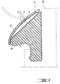
- Figure 3 shows a second embodiment of a sealing ring.
- a main torus 1 that rests on an abutment can be connected to the pipe at the tip end. It but do not rule out that the sealing ring is under tension is inserted in appropriate grooves or by anchoring in the pipe material, preferably on the socket side, is held.
- the main torus 1 has a sliding surface 2 on which the End of a tube can be pushed on.
- the sliding surface is provided with the lubricant layer 5.
- the lubricant layer 5 is covered by a protective strip 3 ' protected, which has been extruded together with the main torus 1 and is made of another, coextrudable material.
- the protective strip 3 ' is over a thin material web 6 connected to the main torus 1.
- the material web 6 is at the main torus at the tube tip end 18 facing Side attached.
- the protective strip 3 At its rear end, the protective strip 3 'ends like a lip resting on the main torus, he is there with this connected by a tearable adhesive 19.
- the Elements 6 and 19 allow the protective strip to be removed easily 3 'from the main torus.
- the protective strip can be applied before bonding can be folded down and is dashed as in Figure 3 shown.
- the cavity 4 between the sliding surface 2 and the protective strip 3 is formed with be filled with a lubricant.
- a locking element can also be provided on the upper half can, that with a located on the main torus 1 Counter element can be locked.
- the Inside of the protective strip with an adhesion reducing Coating 11, in particular with a siliconized Layer is provided.
- the fresh one Lubricant layer with an anti-adhesion coating to dust for example from quartz flour, talc or Graphite.
- quartz sand with a grain size can also be used 0.2 to 0.4 mm, as offered in the building materials trade will be dusted.
- flocking with plastic microparticles made of PTFE or with a fleece pad conceivable.
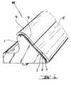
- FIG. 4 Such an adhesion-reducing coating is shown in FIG. 4 provided with the reference number 12.
- an embodiment can also be used be selected in which the protective strip consists of two wing-like halves 13, 13 ', each one-sided easily removable on an outer edge of the sliding surface 2 are attached.
- the lubricant can in this embodiment by means of a nozzle that goes into the central opening is retractable between the two wing-like halves, be pushed in.
Landscapes
- Engineering & Computer Science (AREA)
- General Engineering & Computer Science (AREA)
- Mechanical Engineering (AREA)
- Gasket Seals (AREA)
- Joints With Sleeves (AREA)
- Flanged Joints, Insulating Joints, And Other Joints (AREA)
- Non-Disconnectible Joints And Screw-Threaded Joints (AREA)
Description
Claims (4)
- Dichtring (100) aus einem Elastomer für eine Steckmuffenverbindung, zum Abdichten des Spaltes zwischen Enden von Rohren aus hartem Material (Beton oder ein anderes keramisches Material, Kunststoff, Metall), mit einem Haupttorus aus einem Elastomer, der eine Aufgleitfläche (2) besitzt, über die die Rohrverbindung selbstzentrierend herstellbar ist, wobei der Haupttorus (1) des Dichtringes (100) im Bereich der Aufgleitfläche (2) mit wenigstens einem umlaufenden, leicht entfernbaren Schutzstreifen (3,3') verbunden ist, der die Aufgleitfläche (2) zunächst abdeckt und zwischen seiner Unterseite und der Aufgleitfläche einen Hohlraum (4) beläßt, und wobei die Aufgleitfläche (2) mit einer unterhalb des Schutzstreifens (3,3') liegenden Gleitmittelschicht (5) versehen ist,
dadurch gekennzeichnet, daß
die Gleitmittelschicht (5) an ihrer der Innenseite des Schutzstreifens (3,3') zugewandten Seite oder die Innenseite des Schutzstreifens (3,3') mit einer adhäsionsmindernden Beschichtung (12,11) versehen ist. - Dichtring nach Anspruch 1, dadurch gekennzeichnet, daß die an der Gleitmittelschicht (5) angebrachte, adhäsionsmindernde Beschichtung (12) aus Quarzmehl, Talkum, Graphit, einer Beflockung oder einer Vliesauflage besteht.
- Dichtring nach Anspruch 1, dadurch gekennzeichnet, daß die Innenseite des Schutzstreifens (3,3') mit einer silikonisierten Schicht versehen ist.
- Dichtring nach einem der vorhergehenden Ansprüche, dadurch gekennzeichnet, daß der Schutzstreifen (3,3') aus zwei flügelartigen Hälften (13,13') besteht, die jeweils einseitig an einer peripheren Außenkante (21,22) der Aufgleitfläche (2) leicht entfernbar angebracht sind.
Applications Claiming Priority (3)
| Application Number | Priority Date | Filing Date | Title |
|---|---|---|---|
| DE19611080 | 1996-03-21 | ||
| DE19611080 | 1996-03-21 | ||
| PCT/EP1997/001340 WO1997035138A1 (de) | 1996-03-21 | 1997-03-18 | Dichtring für eine rohrverbindung |
Publications (2)
| Publication Number | Publication Date |
|---|---|
| EP0888511A1 EP0888511A1 (de) | 1999-01-07 |
| EP0888511B1 true EP0888511B1 (de) | 2000-03-01 |
Family
ID=7788931
Family Applications (1)
| Application Number | Title | Priority Date | Filing Date |
|---|---|---|---|
| EP97908252A Expired - Lifetime EP0888511B1 (de) | 1996-03-21 | 1997-03-18 | Dichtring für eine rohrverbindung |
Country Status (5)
| Country | Link |
|---|---|
| EP (1) | EP0888511B1 (de) |
| AT (1) | ATE190122T1 (de) |
| DE (1) | DE59701174D1 (de) |
| ES (1) | ES2145582T3 (de) |
| WO (1) | WO1997035138A1 (de) |
Families Citing this family (4)
| Publication number | Priority date | Publication date | Assignee | Title |
|---|---|---|---|---|
| GB9723561D0 (en) * | 1997-11-08 | 1998-01-07 | Glynwed Pipe Systems Ltd | Jointing ring or gasket and joints incorporating the same |
| DE19945151C1 (de) * | 1999-09-21 | 2001-07-26 | Fraunhofer Ges Forschung | Dichtung für Rohrverbindungen |
| DE10006294A1 (de) * | 2000-02-14 | 2001-08-30 | Macon Verbaugeraete Gmbh | Verfahren zum Aufbringen von Gleitmittel auf eine Rohrdichtung |
| SE528014C2 (sv) | 2005-01-27 | 2006-08-08 | Trelleborg Forsheda Building A | Tätningsring |
Family Cites Families (5)
| Publication number | Priority date | Publication date | Assignee | Title |
|---|---|---|---|---|
| EP0011919B1 (de) * | 1978-10-27 | 1982-07-28 | A/S Den Norske Remfabrik | Dichtung aus Gummi oder ähnlichem Material |
| DE3702477A1 (de) * | 1987-01-28 | 1988-08-11 | Gerhard Preisendoerfer | Abdichtung an steckmuffenverbindungen von betonrohren |
| SE463688B (sv) * | 1987-05-27 | 1991-01-07 | Forsheda Ab | Taetningsring |
| DE4229609C2 (de) * | 1992-09-04 | 2003-05-08 | Forsheda Stefa Gmbh | Abdichtung zwischen zwei ineinandersteckbaren Teilen |
| SE9402394L (sv) * | 1994-07-06 | 1996-01-07 | Skega Ab | Tätningsarrangemang för en rörförbindning |
-
1997
- 1997-03-18 EP EP97908252A patent/EP0888511B1/de not_active Expired - Lifetime
- 1997-03-18 DE DE59701174T patent/DE59701174D1/de not_active Expired - Fee Related
- 1997-03-18 AT AT97908252T patent/ATE190122T1/de not_active IP Right Cessation
- 1997-03-18 ES ES97908252T patent/ES2145582T3/es not_active Expired - Lifetime
- 1997-03-18 WO PCT/EP1997/001340 patent/WO1997035138A1/de active IP Right Grant
Also Published As
| Publication number | Publication date |
|---|---|
| DE59701174D1 (de) | 2000-04-06 |
| ATE190122T1 (de) | 2000-03-15 |
| EP0888511A1 (de) | 1999-01-07 |
| ES2145582T3 (es) | 2000-07-01 |
| WO1997035138A1 (de) | 1997-09-25 |
Similar Documents
| Publication | Publication Date | Title |
|---|---|---|
| DE69414098T2 (de) | Mit versteifungselement im randbereich versehenen abdeckband und verfahren zur abdeckung von dichtungen | |
| DE2432358A1 (de) | Befestigungsvorrichtung | |
| DE2504210A1 (de) | Windelverschluss | |
| DE2736922A1 (de) | Windelverschluss | |
| EP0825052B1 (de) | Befestigung einer Fensterscheibe in einem Kraftfahrzeug | |
| EP0255916A1 (de) | Auf eine Blechkante einer Fahrzeugkarosserie aufzusetzendes Dichtungsprofil | |
| WO2013104358A1 (de) | Kfz-dichtung | |
| EP0077918A1 (de) | Steckmuffendichtung für Betonrohre | |
| DE2605550C2 (de) | Windelverschluß | |
| EP0888511B1 (de) | Dichtring für eine rohrverbindung | |
| DE29610642U1 (de) | Schaumstoffstreifen | |
| DE19529521A1 (de) | Wasserablauf am Rahmen eines öffnungsfähigen Fahrzeugdaches | |
| EP1032503A1 (de) | Dichtsystem mit dichtungsprofil und klebeband | |
| DE3400038A1 (de) | Extrudierter abdeckstreifen fuer kraftfahrzeugkarosserien und extruderkopf zur herstellung eines solchen abdeckstreifens | |
| DE29806536U1 (de) | Selbstklebende Materialbahn | |
| DE202006011989U1 (de) | Luftfilterelement mit abgedeckten Endscheiben | |
| WO1999049986A1 (de) | Kunststoffprofil zur spaltabdichtung von zwei karosserieteilen von fahrzeugen | |
| DE1280527B (de) | Profilstrang mit Klemmlippen zur Fugendichtung | |
| EP3328954A2 (de) | Release liner | |
| DE69321133T2 (de) | Klebeband zum schutz von gummidichtungen | |
| DE10312452A1 (de) | Wundversorgungsprodukt mit Abziehhilfe und Verfahren zur Herstellung desselben | |
| DE19801019B4 (de) | Abdichtende Steckverbindung | |
| EP0832630A1 (de) | Verschlussband für eine Höschenwindel | |
| DE4406728C2 (de) | Unterlagstreifen für Sanitärobjekte | |
| DE29917446U1 (de) | Abdichtkörper, insbesondere zur Abdichtung von Karosseriespalten für Reparaturlackierungen an Karosserieteilen von Kraftfahrzeugen |
Legal Events
| Date | Code | Title | Description |
|---|---|---|---|
| PUAI | Public reference made under article 153(3) epc to a published international application that has entered the european phase |
Free format text: ORIGINAL CODE: 0009012 |
|
| 17P | Request for examination filed |
Effective date: 19980822 |
|
| AK | Designated contracting states |
Kind code of ref document: A1 Designated state(s): AT BE CH DE ES FR GB IT LI NL SE |
|
| RBV | Designated contracting states (corrected) |
Designated state(s): AT BE CH DE ES FR GB IT LI NL SE |
|
| GRAG | Despatch of communication of intention to grant |
Free format text: ORIGINAL CODE: EPIDOS AGRA |
|
| 17Q | First examination report despatched |
Effective date: 19990429 |
|
| GRAG | Despatch of communication of intention to grant |
Free format text: ORIGINAL CODE: EPIDOS AGRA |
|
| GRAH | Despatch of communication of intention to grant a patent |
Free format text: ORIGINAL CODE: EPIDOS IGRA |
|
| RAP1 | Party data changed (applicant data changed or rights of an application transferred) |
Owner name: PHOENIX AKTIENGESELLSCHAFT |
|
| GRAH | Despatch of communication of intention to grant a patent |
Free format text: ORIGINAL CODE: EPIDOS IGRA |
|
| GRAA | (expected) grant |
Free format text: ORIGINAL CODE: 0009210 |
|
| AK | Designated contracting states |
Kind code of ref document: B1 Designated state(s): AT BE CH DE ES FR GB IT LI NL SE |
|
| REF | Corresponds to: |
Ref document number: 190122 Country of ref document: AT Date of ref document: 20000315 Kind code of ref document: T |
|
| REG | Reference to a national code |
Ref country code: CH Ref legal event code: EP |
|
| REF | Corresponds to: |
Ref document number: 59701174 Country of ref document: DE Date of ref document: 20000406 |
|
| REG | Reference to a national code |
Ref country code: CH Ref legal event code: NV Representative=s name: E. BLUM & CO. PATENTANWAELTE |
|
| ET | Fr: translation filed | ||
| ITF | It: translation for a ep patent filed | ||
| REG | Reference to a national code |
Ref country code: ES Ref legal event code: FG2A Ref document number: 2145582 Country of ref document: ES Kind code of ref document: T3 |
|
| GBT | Gb: translation of ep patent filed (gb section 77(6)(a)/1977) |
Effective date: 20000619 |
|
| PLBE | No opposition filed within time limit |
Free format text: ORIGINAL CODE: 0009261 |
|
| STAA | Information on the status of an ep patent application or granted ep patent |
Free format text: STATUS: NO OPPOSITION FILED WITHIN TIME LIMIT |
|
| 26N | No opposition filed | ||
| REG | Reference to a national code |
Ref country code: GB Ref legal event code: IF02 |
|
| PGFP | Annual fee paid to national office [announced via postgrant information from national office to epo] |
Ref country code: GB Payment date: 20030210 Year of fee payment: 7 |
|
| PGFP | Annual fee paid to national office [announced via postgrant information from national office to epo] |
Ref country code: AT Payment date: 20030213 Year of fee payment: 7 |
|
| PGFP | Annual fee paid to national office [announced via postgrant information from national office to epo] |
Ref country code: CH Payment date: 20030225 Year of fee payment: 7 |
|
| PGFP | Annual fee paid to national office [announced via postgrant information from national office to epo] |
Ref country code: ES Payment date: 20030320 Year of fee payment: 7 |
|
| PG25 | Lapsed in a contracting state [announced via postgrant information from national office to epo] |
Ref country code: GB Free format text: LAPSE BECAUSE OF NON-PAYMENT OF DUE FEES Effective date: 20040318 Ref country code: AT Free format text: LAPSE BECAUSE OF NON-PAYMENT OF DUE FEES Effective date: 20040318 |
|
| PG25 | Lapsed in a contracting state [announced via postgrant information from national office to epo] |
Ref country code: ES Free format text: LAPSE BECAUSE OF NON-PAYMENT OF DUE FEES Effective date: 20040320 |
|
| PG25 | Lapsed in a contracting state [announced via postgrant information from national office to epo] |
Ref country code: LI Free format text: LAPSE BECAUSE OF NON-PAYMENT OF DUE FEES Effective date: 20040331 Ref country code: CH Free format text: LAPSE BECAUSE OF NON-PAYMENT OF DUE FEES Effective date: 20040331 |
|
| GBPC | Gb: european patent ceased through non-payment of renewal fee |
Effective date: 20040318 |
|
| REG | Reference to a national code |
Ref country code: CH Ref legal event code: PL |
|
| PG25 | Lapsed in a contracting state [announced via postgrant information from national office to epo] |
Ref country code: IT Free format text: LAPSE BECAUSE OF NON-PAYMENT OF DUE FEES Effective date: 20050318 |
|
| REG | Reference to a national code |
Ref country code: ES Ref legal event code: FD2A Effective date: 20040320 |
|
| PGFP | Annual fee paid to national office [announced via postgrant information from national office to epo] |
Ref country code: SE Payment date: 20070313 Year of fee payment: 11 Ref country code: NL Payment date: 20070313 Year of fee payment: 11 |
|
| PGFP | Annual fee paid to national office [announced via postgrant information from national office to epo] |
Ref country code: BE Payment date: 20070419 Year of fee payment: 11 |
|
| PGFP | Annual fee paid to national office [announced via postgrant information from national office to epo] |
Ref country code: FR Payment date: 20070319 Year of fee payment: 11 |
|
| PGFP | Annual fee paid to national office [announced via postgrant information from national office to epo] |
Ref country code: DE Payment date: 20071217 Year of fee payment: 12 |
|
| BERE | Be: lapsed |
Owner name: PHOENIX A.G. Effective date: 20080331 |
|
| EUG | Se: european patent has lapsed | ||
| PG25 | Lapsed in a contracting state [announced via postgrant information from national office to epo] |
Ref country code: NL Free format text: LAPSE BECAUSE OF NON-PAYMENT OF DUE FEES Effective date: 20081001 |
|
| NLV4 | Nl: lapsed or anulled due to non-payment of the annual fee |
Effective date: 20081001 |
|
| REG | Reference to a national code |
Ref country code: FR Ref legal event code: ST Effective date: 20081125 |
|
| PG25 | Lapsed in a contracting state [announced via postgrant information from national office to epo] |
Ref country code: SE Free format text: LAPSE BECAUSE OF NON-PAYMENT OF DUE FEES Effective date: 20080319 |
|
| PG25 | Lapsed in a contracting state [announced via postgrant information from national office to epo] |
Ref country code: BE Free format text: LAPSE BECAUSE OF NON-PAYMENT OF DUE FEES Effective date: 20080331 |
|
| PG25 | Lapsed in a contracting state [announced via postgrant information from national office to epo] |
Ref country code: FR Free format text: LAPSE BECAUSE OF NON-PAYMENT OF DUE FEES Effective date: 20080331 |
|
| PG25 | Lapsed in a contracting state [announced via postgrant information from national office to epo] |
Ref country code: DE Free format text: LAPSE BECAUSE OF NON-PAYMENT OF DUE FEES Effective date: 20091001 |