EP0887909B1 - Apparatus and method for driving a winding head of a stator winding machine - Google Patents
Apparatus and method for driving a winding head of a stator winding machine Download PDFInfo
- Publication number
- EP0887909B1 EP0887909B1 EP98111494A EP98111494A EP0887909B1 EP 0887909 B1 EP0887909 B1 EP 0887909B1 EP 98111494 A EP98111494 A EP 98111494A EP 98111494 A EP98111494 A EP 98111494A EP 0887909 B1 EP0887909 B1 EP 0887909B1
- Authority
- EP
- European Patent Office
- Prior art keywords
- shaft
- driving shaft
- counterweight
- axis
- drive means
- Prior art date
- Legal status (The legal status is an assumption and is not a legal conclusion. Google has not performed a legal analysis and makes no representation as to the accuracy of the status listed.)
- Expired - Lifetime
Links
- 238000004804 winding Methods 0.000 title claims abstract description 52
- 238000000034 method Methods 0.000 title claims abstract description 11
- WABPQHHGFIMREM-UHFFFAOYSA-N lead(0) Chemical compound [Pb] WABPQHHGFIMREM-UHFFFAOYSA-N 0.000 claims description 6
- 230000010355 oscillation Effects 0.000 description 4
- 230000007935 neutral effect Effects 0.000 description 2
- 230000000712 assembly Effects 0.000 description 1
- 238000000429 assembly Methods 0.000 description 1
- 230000001419 dependent effect Effects 0.000 description 1
- 239000002184 metal Substances 0.000 description 1
- 230000000630 rising effect Effects 0.000 description 1
- 230000001360 synchronised effect Effects 0.000 description 1
Images


Classifications
-
- H—ELECTRICITY
- H02—GENERATION; CONVERSION OR DISTRIBUTION OF ELECTRIC POWER
- H02K—DYNAMO-ELECTRIC MACHINES
- H02K15/00—Processes or apparatus specially adapted for manufacturing, assembling, maintaining or repairing of dynamo-electric machines
- H02K15/08—Forming windings by laying conductors into or around core parts
- H02K15/095—Forming windings by laying conductors into or around core parts by laying conductors around salient poles
-
- Y—GENERAL TAGGING OF NEW TECHNOLOGICAL DEVELOPMENTS; GENERAL TAGGING OF CROSS-SECTIONAL TECHNOLOGIES SPANNING OVER SEVERAL SECTIONS OF THE IPC; TECHNICAL SUBJECTS COVERED BY FORMER USPC CROSS-REFERENCE ART COLLECTIONS [XRACs] AND DIGESTS
- Y10—TECHNICAL SUBJECTS COVERED BY FORMER USPC
- Y10T—TECHNICAL SUBJECTS COVERED BY FORMER US CLASSIFICATION
- Y10T74/00—Machine element or mechanism
- Y10T74/16—Alternating-motion driven device with means during operation to adjust stroke
- Y10T74/1625—Stroke adjustable to zero and/or reversible in phasing
- Y10T74/1675—Crank pin drive, shiftable pin
Definitions
- the present invention relates to a stator winding machine for electric motors.
- the invention relates to a method for driving a winding head of a stator winding machine, such head comprising a wire winding shaft with adjustable stroke.
- the invention relates to an apparatus for driving such a winding head.
- the wire winding step is carried out by a winding head comprising a winding hollow shaft through which the wire slides.
- the wire enters the hollow shaft at one of its ends after having been unwound in a braked way from a reel and exits at its other end through one or more wire guiding needles.
- the hollow shaft motion comprises a reciprocation parallel to the axis of the stator and an oscillation about the axis of the shaft, so that the needles follow a substantially elliptical path and are capable of winding the wire about the poles of the stator.
- the wire laying step in the recesses of the stator is aided by wire guiding shrouds of known type.
- the path followed by the wire out of the needles, whose motion is substantially elliptical, is, then, tangential to the wire guiding shrouds which lay the wire into the recesses provided for about the poles.
- needles are provided for having an independent motion from each other and driven by means of rods coaxial to the hollow shaft. This way, the wire guiding shrouds can be omitted, even if a more complex driving mechanism is necessary.
- crank gear drive for example described in US4158314 and US 5560554 .
- crank and slotted link described in the above cited EP0538905 is also known, which transforms the rotation of a driving shaft into a reciprocation of the hollow shaft.
- a rocking lever drive is commonly used, a end of which is driven by a cam gear operated by the driving shaft, whereas the other end has a ring gear portion which engages with a pinion coaxial to the hollow shaft.
- One of the main problems of the known kinematic apparatus is the quick adjustment of the reciprocation stroke of the hollow shaft.
- the adjustment which should be carried out without opening every time the machine, is necessary because stators must be wound with different pack height, which is substantially equal to the longitudinal diameter of the elliptical path of the needles. Since, therefore, the stators, which in order to be wound are carried by automatic conveyors which bring them in succession to the winding machine automatic, cannot have the same pack height, require, thus, a quick adjustment of the stroke of the hollow shaft.
- stator winding machines described in the above cited documents are all provided with kinematic apparatus capable of adjusting the stroke quickly and, in some cases, of carrying out the balancing at the same time.
- the problem of the adjustment of the reciprocation stroke has been solved successfully, in several different ways.
- these known devices do not carry out satisfactorily a balancing of the inertial counterweights.
- only some components of the rocking eccentrical forces are balanced, i.e. the forces parallel to the axis of the hollow shaft, whereas the moments of the rocking forces are not balanced, and sometimes worsened, as in EP0538905 . This causes high noises and seriously limits the top working speed, owing to the strong vibration rising at the increase of the winding speed.
- a further object of the present invention is to provide a method for balancing the rocking forces and their moments in an apparatus for driving with adjustable stroke the reciprocation of the hollow shaft of a stator winding machine.
- a stator winding machine operating with the method and equipped with the apparatus according to the present invention, comprises a box 1 having two supports 2 and 3 in which a winding head comprising a hollow shaft 5 longitudinally slidingly engages according to axis 4 and pivotally engages always about axis 4.
- Shaft 5 has an end having an inlet 6 for the lead wire and at the other end has two opposite outlet needles 7 oriented orthogonally to axis 4.
- Hollow shaft 5 reciprocates according to arrows 8 and oscillates according to arrows 9, respectively longitudinally to and about axis 4.
- the winding machine is operated by a motor 10, which, by means of a belt 11, rotates a driving shaft 12 which has, at its end opposite to belt 11, rocking drive means 13 which engage with a sleeve 14 integral to hollow shaft 5.
- the oscillation according to arrows 9 is obtained through a secondary shaft 17 which operates, by means of not shown cam means, a toothed rocking lever 18 rotatable about a pivot 19 and which causes a pinion 20 to oscillate, which engages with a grooved portion 21 of hollow shaft 5.
- the rocking drive means 13 comprises a bar 22 integral to sleeve 14 and extending orthogonally to both hollow shaft 5 and driving shaft 12.
- bar 22 two rows of rollers 23 engage, pivotally mounted on an eccentric support 24.
- the latter belongs to a first flywheel 25 integral to the driving shaft 12 and comprises a first counterweight 26, opposite to the eccentric support 24 with respect to the axis of the driving shaft 12.
- Flywheel 25 has, moreover, an adjusting head 27 integral to a screw 28 which engages both with a nut screw 26b made in counterweight 26 and, through a screw threaded portion of opposite direction, with a nut screw 24b belonging to eccentric support 24.
- Flywheel 25 rotates in a plane 25a parallel to hollow shaft 5 and orthogonal to driving shaft 12.
- a second flywheel 30 is provided for which rotates in a plane 30a, parallel to plane 25a and has a second counterweight 31 with a nut screw 31b in which an adjustment screw 32 with an adjustment head 33 engages.
- Flywheel 30 is integral to a shaft 34 coaxial to the driving shaft 12 but counter rotating with respect to the latter through bevel gears drive.
- This drive comprises bevel gears 35, 36 and 37 respectively integral to the driving shaft 12, pivoted on a fixed support 38 of box 1, and integral to coaxial shaft 34.
- the gear ratio is chosen so that the motion of the second flywheel 30 is opposite to that of the first flywheel 25.
- An adjustment device 39 ( fig. 1 ), which can be operated by a handle 40 or, alternatively, automatically, has two spanners 41 which engage with adjustment heads 27 and 32, respectively of the first and of the second flywheel 25 and 30, when they are still and aligned to each other, as shown in figure 2 .
- the rotation of adjustment head 27 of flywheel 25 causes first counterweight 26 and eccentric support 24 to move towards/away from each other, zeroing the resultant of the centrifugal forces parallel to axis 4.
- the rotation of head 32 causes a shifting of the second counterweight 31 towards/away from the driving shaft 12 axis, creating an alternate centrifugal force whose moment with respect to a neutral axis of the rocking forces parallel to the axis 4 makes zero the alternate forces and minimises the moment of the resultant of the rocking forces.
- the pitch of screws 28 and 33 is chosen after a calculus easy for a skilled man, so that, for every position of the eccentric support 24, corresponding to a particular reciprocation stroke 8 of needles 7, the balance conditions of the rocking forces and of the moments of the rocking forces are fulfilled.
- the choice of counterweights 26 and 31 is made roughly by means of mathematical calculus and, then, calibrated when the winding machine is tested by means of known balancing apparatus.
- the amount of the rotation of spanners 41 of the adjustment device 39 ( fig. 1 ), when this is pushed against heads 27 and 32, is proportional to the reciprocation stroke adjustment of hollow shaft 5.
- the adjustment device 40 is operated manually. If, on the other hand, the machine has to be more flexible, i.e. winding stators having different pack height in succession, the adjustment device 40 is replaced by an equivalent automatic device operated in a known way by the computer which controls the winding machine.
- the rocking drive means 13 the presence of bar 22 is particularly advantageous since the counterweight of the rocking forces which are integral to the hollow shaft 5 is minimised.
Landscapes
- Engineering & Computer Science (AREA)
- Manufacturing & Machinery (AREA)
- Power Engineering (AREA)
- Manufacture Of Motors, Generators (AREA)
Abstract
Description
- The present invention relates to a stator winding machine for electric motors.
- More precisely, the invention relates to a method for driving a winding head of a stator winding machine, such head comprising a wire winding shaft with adjustable stroke.
- Moreover, the invention relates to an apparatus for driving such a winding head.
- Many types of electric motors stators have coils of electrically insulated lead wire wound about poles protruding in recesses of a shaped body formed by a pack of metal layers. The wire winding step, according to a well known technique, is carried out by a winding head comprising a winding hollow shaft through which the wire slides. The wire enters the hollow shaft at one of its ends after having been unwound in a braked way from a reel and exits at its other end through one or more wire guiding needles. The hollow shaft motion comprises a reciprocation parallel to the axis of the stator and an oscillation about the axis of the shaft, so that the needles follow a substantially elliptical path and are capable of winding the wire about the poles of the stator.
- The wire laying step in the recesses of the stator is aided by wire guiding shrouds of known type. The path followed by the wire out of the needles, whose motion is substantially elliptical, is, then, tangential to the wire guiding shrouds which lay the wire into the recesses provided for about the poles.
- In some cases, as described in
EP0538905 , instead of needles integral to the end of the hollow shaft, needles are provided for having an independent motion from each other and driven by means of rods coaxial to the hollow shaft. This way, the wire guiding shrouds can be omitted, even if a more complex driving mechanism is necessary. - The reciprocation and oscillation of the winding shaft, as known, are given by means of different kinematic apparatus, synchronised to each other and, normally, operated by a single motor through mechanic drive and gears. In particular, for the reciprocation, a crank gear drive is known, for example described in
US4158314 andUS 5560554 . Alternatively, a crank and slotted link described in the above citedEP0538905 is also known, which transforms the rotation of a driving shaft into a reciprocation of the hollow shaft. On the other hand, concerning the oscillation of the hollow shaft, a rocking lever drive is commonly used, a end of which is driven by a cam gear operated by the driving shaft, whereas the other end has a ring gear portion which engages with a pinion coaxial to the hollow shaft. - One of the main problems of the known kinematic apparatus is the quick adjustment of the reciprocation stroke of the hollow shaft. In particular, the adjustment, which should be carried out without opening every time the machine, is necessary because stators must be wound with different pack height, which is substantially equal to the longitudinal diameter of the elliptical path of the needles. Since, therefore, the stators, which in order to be wound are carried by automatic conveyors which bring them in succession to the winding machine automatic, cannot have the same pack height, require, thus, a quick adjustment of the stroke of the hollow shaft.
- However, if on one hand there is the main problem to adjust quickly the reciprocation stroke, by changing the lever arms of the reciprocating elements using external controls, on the other hand there is the problem of balancing the inertial counterweights thereof. Moreover, the higher is the oscillating frequency, which is equal to the number of turns wound in a time unit, the more is this problem complicated and hard.
- The stator winding machines described in the above cited documents are all provided with kinematic apparatus capable of adjusting the stroke quickly and, in some cases, of carrying out the balancing at the same time. In them, the problem of the adjustment of the reciprocation stroke has been solved successfully, in several different ways. On the other hand, these known devices do not carry out satisfactorily a balancing of the inertial counterweights. In fact, only some components of the rocking eccentrical forces are balanced, i.e. the forces parallel to the axis of the hollow shaft, whereas the moments of the rocking forces are not balanced, and sometimes worsened, as in
EP0538905 . This causes high noises and seriously limits the top working speed, owing to the strong vibration rising at the increase of the winding speed. - In
US 4,158,314 inertia forces caused by translation strokes of the winding shaft are balanced by a counterbalance carriage, which translates opposite to the winding shaft.US 4,361,056 balances inertia forces by rotating balancing amasses, which are not adapted to balance variations in the stroke of the winding shaft. - It is, therefore, object of the present invention to provide a stator winding machine which is equipped with a winding head driving apparatus whose stroke is quickly adjustable, and wherein the rocking forces can be balanced as well as the moments of these forces can be minimised by using rotating balancing masses that can be adjusted when the winding head stroke needs to be changed.
- It is another object of the present invention to provide such a machine in which an easy operation from the outside of the adjustment controls of the reciprocation is possible both to adjust the stroke and for balancing.
- It is, also, object of the present invention that such a machine has rocking inertial counterweights whose moments are less than in the prior art.
- A further object of the present invention is to provide a method for balancing the rocking forces and their moments in an apparatus for driving with adjustable stroke the reciprocation of the hollow shaft of a stator winding machine.
- These and other objects are achieved by the apparatus and method according to the invention as defined in the
independent claims - Further characteristics and advantages of the stator winding apparatus and method according to the invention will be made clearer with the following, but not limitative, exemplifying description with reference to the attached drawings, wherein:
-
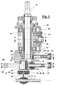
figure 1 shows a top plan partially cross sectioned view of a stator winding machine according to the present invention; -
figure 2 shows cross sectional view of the balancing assembly of the rocking drive means of the machine offigure 1 ; -
figures 3, 4 and 5 show the assembly offigure 2 respectively cross sectioned according to arrows III-III, IV-IV and V-V. - With reference to the above referenced figures, a stator winding machine, operating with the method and equipped with the apparatus according to the present invention, comprises a
box 1 having twosupports hollow shaft 5 longitudinally slidingly engages according toaxis 4 and pivotally engages always aboutaxis 4. Shaft 5 has an end having aninlet 6 for the lead wire and at the other end has twoopposite outlet needles 7 oriented orthogonally toaxis 4. -
Hollow shaft 5 reciprocates according toarrows 8 and oscillates according toarrows 9, respectively longitudinally to and aboutaxis 4. - The winding machine is operated by a
motor 10, which, by means of abelt 11, rotates adriving shaft 12 which has, at its end opposite to belt 11, rocking drive means 13 which engage with asleeve 14 integral tohollow shaft 5. - The oscillation according to
arrows 9 is obtained through asecondary shaft 17 which operates, by means of not shown cam means, a toothed rockinglever 18 rotatable about apivot 19 and which causes a pinion 20 to oscillate, which engages with agrooved portion 21 ofhollow shaft 5. - With reference to
figure 2 and to the cross sectional view offigures 3, 4 and 5 , the rocking drive means 13 comprises abar 22 integral tosleeve 14 and extending orthogonally to bothhollow shaft 5 anddriving shaft 12. Withbar 22 two rows ofrollers 23 engage, pivotally mounted on aneccentric support 24. The latter belongs to afirst flywheel 25 integral to the drivingshaft 12 and comprises afirst counterweight 26, opposite to theeccentric support 24 with respect to the axis of thedriving shaft 12. Flywheel 25 has, moreover, an adjustinghead 27 integral to ascrew 28 which engages both with anut screw 26b made incounterweight 26 and, through a screw threaded portion of opposite direction, with anut screw 24b belonging toeccentric support 24.Flywheel 25 rotates in aplane 25a parallel tohollow shaft 5 and orthogonal to drivingshaft 12. - Always according to the invention, a
second flywheel 30 is provided for which rotates in aplane 30a, parallel to plane 25a and has asecond counterweight 31 with anut screw 31b in which an adjustment screw 32 with anadjustment head 33 engages. Flywheel 30 is integral to ashaft 34 coaxial to the drivingshaft 12 but counter rotating with respect to the latter through bevel gears drive. This drive comprisesbevel gears driving shaft 12, pivoted on afixed support 38 ofbox 1, and integral tocoaxial shaft 34. The gear ratio is chosen so that the motion of thesecond flywheel 30 is opposite to that of thefirst flywheel 25. - An adjustment device 39 (
fig. 1 ), which can be operated by ahandle 40 or, alternatively, automatically, has twospanners 41 which engage withadjustment heads second flywheel figure 2 . - More precisely, the rotation of
adjustment head 27 offlywheel 25 causesfirst counterweight 26 andeccentric support 24 to move towards/away from each other, zeroing the resultant of the centrifugal forces parallel toaxis 4. The rotation ofhead 32, on the other hand, causes a shifting of thesecond counterweight 31 towards/away from thedriving shaft 12 axis, creating an alternate centrifugal force whose moment with respect to a neutral axis of the rocking forces parallel to theaxis 4 makes zero the alternate forces and minimises the moment of the resultant of the rocking forces. - Obviously, the pitch of
screws eccentric support 24, corresponding to aparticular reciprocation stroke 8 ofneedles 7, the balance conditions of the rocking forces and of the moments of the rocking forces are fulfilled. The choice ofcounterweights - The amount of the rotation of
spanners 41 of the adjustment device 39 (fig. 1 ), when this is pushed againstheads hollow shaft 5. - When, through
needles 7 andhollow shaft 5, lead wire must be laid in the in the recesses of a stator having a determined pack height, it is sufficient, by means of theadjustment device 40, to rotateheads flywheels shaft 12 stops. - If the winding machine is winding groups of stators having the same pack height, it is sufficient that, at every height change, when the driving shaft is still, the
adjustment device 40 is operated manually. If, on the other hand, the machine has to be more flexible, i.e. winding stators having different pack height in succession, theadjustment device 40 is replaced by an equivalent automatic device operated in a known way by the computer which controls the winding machine. - Concerning, finally, the rocking drive means 13, the presence of
bar 22 is particularly advantageous since the counterweight of the rocking forces which are integral to thehollow shaft 5 is minimised. In fact, theeccentric support 24, which carries therollers 23 and is heavier thanbar 22, belongs to flywheel 25, is substantially closed to the neutral axis of the rocking forces, and is a rocking mass compensated bycounterweight 26, thus reducing the overall moments of the resultant of the rocking forces that thesecond counterweight 31 has to compensate. - Obviously, alternatively to the
bar 22 androllers 23 assembly, it is possible to use other equivalent assemblies capable of turning a rotation into an adjustable stroke reciprocation.
Claims (11)
- A stator winding machine for winding electric motors stators with lead wire, comprising an axially hollow shaft (5) having an axis (4) which, in use, is aligned with a stator being wound, said shaft having an inlet end (6) of said lead wire and an outlet end (7) that is suitable for moving through said stators, said shaft reciprocating along said axis and oscillating about said axis, a rocking drive means (13) and a motor means (10) being provided for driving said reciprocation, a means (26,31) being provided for balancing said rocking drive means (18) and for adjusting said reciprocation,
wherein said means for balancing comprises at least two counter rotating counterweights that rotate according to planes (25a,30a) parallel to said axis (4),
characterised in that
said counter rotating counterweights (26,31) are adjustable by moving according to planes (25a,30a) parallel to said axis (4). - Stator winding machine according to claim 1, wherein a driving shaft (12) substantially orthogonal to said axis (4) is provided to which said rocking drive means (18) is eccentrically connected, said means (27,28,24b,24) for balancing and for adjusting said reciprocation comprising means for adjusting the eccentricity of said rocking drive means (18) with respect to said driving shaft (12).
- Stator winding machine according to claim 2, wherein said counterweights comprise a first counterweight (26) rotating integral to said driving shaft (12) and a said second counterweight (31) counter rotating with respect to said driving shaft (12).
- Stator winding machine according to claim 3, wherein a first flywheel (25) is provided for rotating integral to said driving shaft (12) comprising said first counterweight (26) and to which said rocking drive means (18) is connected, a means (27,28,26b,24, 24b) being provided on said first flywheel (25) for adjusting the eccentricity of said rocking drive means (18) and of said first counterweight (26) opposite to each other with respect to said driving shaft (12).
- Stator winding machine according to claim 3, wherein a second flywheel (30) is provided that is integral to a counter rotating shaft (34) coaxial to said driving shaft (12) and comprises said second counterweight (31), said means (31b,32,33) for adjusting the eccentricity of said second counterweight being provided on said second flywheel for adjusting the eccentricity of said second counterweight with respect to said driving shaft (12).
- Stator winding machine according to claims 4 and 5, wherein said means (27,28,26b,24,24b) for adjusting the eccentricity with respect to said driving shaft (12) of said rocking drive means (18) and of said first counterweight (26) on said first flywheel (25), and said means (31b,32,33) for adjusting the eccentricity with respect to said driving shaft (12) of said second counterweight (31) on said second flywheel (30), can be aligned to each other when said driving: shaft (12) is still, an external actuating device (39) being provided engaging with said aligned means for adjusting (27,32).
- Stator winding machine according to claim 2, wherein said rocking drive means (18) comprises a bar (22) orthogonal to a hollow shaft (34) and to said driving shaft (12), said bar having one component of motion parallel and one component of motion orthogonal to said axis (4), said bar being orthogonal to said axis and to said driving shaft.
- Stator winding machine according to claim 1 wherein said adjustment operation occurs from the outside of said machine.
- A method for balancing a stator winding machine, of the type comprising an axially hollow shaft (5) having an axis (4) which, in use, is aligned with a stator being wound, said shaft (5) having an inlet end (6) of said lead wire and an outlet end (7) that is suitable for moving through said stators, said shaft reciprocating along said axis and oscillating about said axis, a rocking drive means (18) and a motor means (10) being provided for driving said reciprocation, a means being provided for balancing said rocking drive means (18) for adjusting said reciprocation, said rocking drive means being eccentrically connected to a driving shaft (12) that is substantially orthogonal to said axis characterised in that it comprises the steps of:- balancing said rocking drive means (18), which rotates in a first plane (25a) parallel to said hollow shaft (5), by providing a first counterweight (26) that is positioned opposite to said rocking drive; means (18) with respect to said driving shaft (12), and- providing a second counterweight (31) which rotates in a second plane (30a) parallel to said first plane (25a), but in a counter rotating way;- adjusting said first and second counterweights (26,31) by moving them according to said first and second planes (25a,30a).
- Method for balancing a stator winding machine according to claim 9, comprising the further steps of- adjusting said reciprocation stroke by shifting contemporaneously said rocking drive means (18) away from/towards said driving shaft (12), said first counterweight (26) away from/towards said rocking drive means (18), and said second counter rotating counterweight (31) away from/towards said driving shaft (12).
- Method; for balancing a stator winding machine according to claim 9, wherein said adjustment operation occurs from the outside of said machine.
Applications Claiming Priority (2)
| Application Number | Priority Date | Filing Date | Title |
|---|---|---|---|
| ITPI970037 | 1997-06-23 | ||
| IT97PI000037A IT1295594B1 (en) | 1997-06-23 | 1997-06-23 | EQUIPMENT AND METHOD FOR DRIVING AND INERTIAL BALANCING WITH VARIABLE STROKE OF A WIRE WINDING SHAFT FOR A MACHINE |
Publications (2)
| Publication Number | Publication Date |
|---|---|
| EP0887909A1 EP0887909A1 (en) | 1998-12-30 |
| EP0887909B1 true EP0887909B1 (en) | 2010-12-15 |
Family
ID=11394125
Family Applications (1)
| Application Number | Title | Priority Date | Filing Date |
|---|---|---|---|
| EP98111494A Expired - Lifetime EP0887909B1 (en) | 1997-06-23 | 1998-06-23 | Apparatus and method for driving a winding head of a stator winding machine |
Country Status (5)
| Country | Link |
|---|---|
| US (1) | US6032897A (en) |
| EP (1) | EP0887909B1 (en) |
| AT (1) | ATE492059T1 (en) |
| DE (1) | DE69842043D1 (en) |
| IT (1) | IT1295594B1 (en) |
Families Citing this family (9)
| Publication number | Priority date | Publication date | Assignee | Title |
|---|---|---|---|---|
| US6622955B2 (en) * | 2000-09-22 | 2003-09-23 | Axis Usa, Inc. | Winder, and methods for stratified winding, of wire onto a dynamo-electric core |
| JP3647374B2 (en) * | 2001-01-09 | 2005-05-11 | 日特エンジニアリング株式会社 | Winding device and winding method |
| EP1369980A1 (en) * | 2002-05-31 | 2003-12-10 | ATOP S.p.A. | Method for winding a multi-pole stator and winding machine |
| US7004420B2 (en) * | 2003-02-13 | 2006-02-28 | Atop S.P.A. | Dynamo-electric core winder |
| US20080016676A1 (en) * | 2006-07-18 | 2008-01-24 | Jones Robert M | Automatic winder for an inside brushless stator |
| US8028396B2 (en) * | 2006-07-18 | 2011-10-04 | Robert M. Jones | Automatic wire winding of inside brushless stator |
| ITTO20070436A1 (en) * | 2007-06-18 | 2008-12-19 | Atop Spa | "APPARATUS AND PROCEDURE FOR WRAPPING AND INSERTING REELS IN DYNAMOELECTRIC MACHINES" |
| ITFI20090061A1 (en) * | 2009-03-26 | 2010-09-27 | G S Engineering Di Stefano Giachi | DEVICE FOR THE CONSTRUCTION OF ELECTRIC WINDINGS |
| IT1403146B1 (en) * | 2010-11-23 | 2013-10-04 | Atop Spa | EQUIPMENT FOR HANDLING OF ELEMENTS OF WIRE DRAINERS USED TO WIND COILS OF COMPONENTS OF ELECTRIC MACHINES. |
Family Cites Families (8)
| Publication number | Priority date | Publication date | Assignee | Title |
|---|---|---|---|---|
| US3112657A (en) * | 1957-11-01 | 1963-12-03 | William F Huck | Reciprocation balancing mechanism |
| US4158314A (en) * | 1977-11-17 | 1979-06-19 | The Globe Tool And Engineering Company | High speed stator winder |
| US4361056A (en) * | 1980-04-23 | 1982-11-30 | Mechaneer, Inc. | Apparatus for producing compound axial and rotary movement of a shaft |
| JPH069760B2 (en) * | 1986-02-17 | 1994-02-09 | 三菱重工業株式会社 | Reciprocating machine balancer |
| JPH01180798A (en) * | 1987-12-29 | 1989-07-18 | Sankyo Seisakusho:Kk | Device for adjusting stroke length of press machine |
| GB2244116B (en) * | 1990-05-16 | 1994-06-01 | Cmb Foodcan Plc | A balanced press machine |
| US5560554A (en) * | 1993-08-31 | 1996-10-01 | Odawara Engineering Co., Ltd. | Stator winding shaft with stroke adjustment |
| JPH07131958A (en) * | 1993-11-04 | 1995-05-19 | Odawara Eng:Kk | Stator winding apparatus |
-
1997
- 1997-06-23 IT IT97PI000037A patent/IT1295594B1/en active IP Right Grant
-
1998
- 1998-06-23 AT AT98111494T patent/ATE492059T1/en not_active IP Right Cessation
- 1998-06-23 EP EP98111494A patent/EP0887909B1/en not_active Expired - Lifetime
- 1998-06-23 US US09/102,646 patent/US6032897A/en not_active Expired - Lifetime
- 1998-06-23 DE DE69842043T patent/DE69842043D1/en not_active Expired - Lifetime
Also Published As
| Publication number | Publication date |
|---|---|
| US6032897A (en) | 2000-03-07 |
| ITPI970037A1 (en) | 1998-12-23 |
| ITPI970037A0 (en) | 1997-06-23 |
| IT1295594B1 (en) | 1999-05-13 |
| ATE492059T1 (en) | 2011-01-15 |
| EP0887909A1 (en) | 1998-12-30 |
| DE69842043D1 (en) | 2011-01-27 |
Similar Documents
| Publication | Publication Date | Title |
|---|---|---|
| EP0318063B1 (en) | Equipment for the actuation of needles for the realization of electric motors field windings | |
| US6098912A (en) | Winding machine having freely positionable nozzle | |
| US6032897A (en) | Apparatus and method for driving a winding head of a stator winding machine | |
| GB2256905A (en) | Counterbalanced reciprocating wobble plate mechanism | |
| JP2000316261A (en) | Winding device | |
| US4158314A (en) | High speed stator winder | |
| EP2186590B1 (en) | Vibration-suppressing mechanism for gear-shaping machine | |
| JP2000175415A (en) | Device for winding to stator core | |
| GB1588675A (en) | Surface-smoothing machines | |
| US2841993A (en) | Drive for hand power tools | |
| US3276275A (en) | Motion transfer mechanism | |
| DK2643922T3 (en) | Apparatus for moving wire delivery elements used to winding coils of core components of dynamoelectric machines. | |
| JPH04226270A (en) | Thread winding method and device | |
| JPH0759308A (en) | Winding machine for outer slot type stator | |
| US2954177A (en) | Winding machine | |
| US3735642A (en) | Curve drive for oscillating motions on winding rods of stator winding machines | |
| JPH11228021A (en) | Traverse device for winder | |
| CN221270008U (en) | A marking and positioning device for synchronous wheel production | |
| EP0389442A2 (en) | Improved apparatus for automatically shaping windings for extremely elongated coils, in particular to form dipole or quadrupole magnets | |
| EP0955716A2 (en) | Method and programmable apparatus for effecting the reciprocation and oscillation in a stator winding machine | |
| SU141205A1 (en) | Machine for winding compact stators of electric motors | |
| JPH05122909A (en) | Outer rotor type winding machine | |
| RU2060922C1 (en) | Device for cross winding of thread on bobbin | |
| CN108732372A (en) | A kind of full-automatic eight channels sample loading gun crossbeam arm | |
| JPH07136367A (en) | sewing machine |
Legal Events
| Date | Code | Title | Description |
|---|---|---|---|
| PUAI | Public reference made under article 153(3) epc to a published international application that has entered the european phase |
Free format text: ORIGINAL CODE: 0009012 |
|
| AK | Designated contracting states |
Kind code of ref document: A1 Designated state(s): AT BE CH CY DE DK ES FI FR GB GR IE LI |
|
| AX | Request for extension of the european patent |
Free format text: AL;LT;LV;MK;RO;SI |
|
| 17P | Request for examination filed |
Effective date: 19990629 |
|
| AKX | Designation fees paid |
Free format text: AT BE CH CY DE DK ES FI FR GB GR IE LI |
|
| AXX | Extension fees paid |
Free format text: SI PAYMENT 19990629 |
|
| 19A | Proceedings stayed before grant |
Effective date: 19991214 |
|
| 19F | Resumption of proceedings before grant (after stay of proceedings) |
Effective date: 20070201 |
|
| 17Q | First examination report despatched |
Effective date: 20071130 |
|
| RBV | Designated contracting states (corrected) |
Designated state(s): AT CH DE DK ES FR GB IE IT LI NL PT SE |
|
| GRAP | Despatch of communication of intention to grant a patent |
Free format text: ORIGINAL CODE: EPIDOSNIGR1 |
|
| GRAS | Grant fee paid |
Free format text: ORIGINAL CODE: EPIDOSNIGR3 |
|
| GRAA | (expected) grant |
Free format text: ORIGINAL CODE: 0009210 |
|
| AK | Designated contracting states |
Kind code of ref document: B1 Designated state(s): AT CH DE DK ES FR GB IE IT LI NL PT SE |
|
| AX | Request for extension of the european patent |
Extension state: SI |
|
| REG | Reference to a national code |
Ref country code: GB Ref legal event code: FG4D Ref country code: CH Ref legal event code: EP |
|
| REG | Reference to a national code |
Ref country code: IE Ref legal event code: FG4D |
|
| REF | Corresponds to: |
Ref document number: 69842043 Country of ref document: DE Date of ref document: 20110127 Kind code of ref document: P |
|
| REG | Reference to a national code |
Ref country code: CH Ref legal event code: NV Representative=s name: HEPP WENGER RYFFEL AG |
|
| REG | Reference to a national code |
Ref country code: NL Ref legal event code: VDEP Effective date: 20101215 |
|
| PG25 | Lapsed in a contracting state [announced via postgrant information from national office to epo] |
Ref country code: SE Free format text: LAPSE BECAUSE OF FAILURE TO SUBMIT A TRANSLATION OF THE DESCRIPTION OR TO PAY THE FEE WITHIN THE PRESCRIBED TIME-LIMIT Effective date: 20101215 Ref country code: NL Free format text: LAPSE BECAUSE OF FAILURE TO SUBMIT A TRANSLATION OF THE DESCRIPTION OR TO PAY THE FEE WITHIN THE PRESCRIBED TIME-LIMIT Effective date: 20101215 Ref country code: AT Free format text: LAPSE BECAUSE OF FAILURE TO SUBMIT A TRANSLATION OF THE DESCRIPTION OR TO PAY THE FEE WITHIN THE PRESCRIBED TIME-LIMIT Effective date: 20101215 |
|
| PG25 | Lapsed in a contracting state [announced via postgrant information from national office to epo] |
Ref country code: ES Free format text: LAPSE BECAUSE OF FAILURE TO SUBMIT A TRANSLATION OF THE DESCRIPTION OR TO PAY THE FEE WITHIN THE PRESCRIBED TIME-LIMIT Effective date: 20110326 Ref country code: PT Free format text: LAPSE BECAUSE OF FAILURE TO SUBMIT A TRANSLATION OF THE DESCRIPTION OR TO PAY THE FEE WITHIN THE PRESCRIBED TIME-LIMIT Effective date: 20110415 |
|
| PLBE | No opposition filed within time limit |
Free format text: ORIGINAL CODE: 0009261 |
|
| STAA | Information on the status of an ep patent application or granted ep patent |
Free format text: STATUS: NO OPPOSITION FILED WITHIN TIME LIMIT |
|
| PG25 | Lapsed in a contracting state [announced via postgrant information from national office to epo] |
Ref country code: DK Free format text: LAPSE BECAUSE OF FAILURE TO SUBMIT A TRANSLATION OF THE DESCRIPTION OR TO PAY THE FEE WITHIN THE PRESCRIBED TIME-LIMIT Effective date: 20101215 |
|
| 26N | No opposition filed |
Effective date: 20110916 |
|
| REG | Reference to a national code |
Ref country code: DE Ref legal event code: R097 Ref document number: 69842043 Country of ref document: DE Effective date: 20110916 |
|
| GBPC | Gb: european patent ceased through non-payment of renewal fee |
Effective date: 20110623 |
|
| REG | Reference to a national code |
Ref country code: FR Ref legal event code: ST Effective date: 20120229 |
|
| REG | Reference to a national code |
Ref country code: IE Ref legal event code: MM4A |
|
| PG25 | Lapsed in a contracting state [announced via postgrant information from national office to epo] |
Ref country code: IE Free format text: LAPSE BECAUSE OF NON-PAYMENT OF DUE FEES Effective date: 20110623 Ref country code: FR Free format text: LAPSE BECAUSE OF NON-PAYMENT OF DUE FEES Effective date: 20110630 |
|
| PG25 | Lapsed in a contracting state [announced via postgrant information from national office to epo] |
Ref country code: GB Free format text: LAPSE BECAUSE OF NON-PAYMENT OF DUE FEES Effective date: 20110623 |
|
| PGFP | Annual fee paid to national office [announced via postgrant information from national office to epo] |
Ref country code: CH Payment date: 20150623 Year of fee payment: 18 Ref country code: DE Payment date: 20150623 Year of fee payment: 18 |
|
| PGFP | Annual fee paid to national office [announced via postgrant information from national office to epo] |
Ref country code: IT Payment date: 20160621 Year of fee payment: 19 |
|
| REG | Reference to a national code |
Ref country code: DE Ref legal event code: R119 Ref document number: 69842043 Country of ref document: DE |
|
| REG | Reference to a national code |
Ref country code: CH Ref legal event code: PL |
|
| PG25 | Lapsed in a contracting state [announced via postgrant information from national office to epo] |
Ref country code: LI Free format text: LAPSE BECAUSE OF NON-PAYMENT OF DUE FEES Effective date: 20160630 Ref country code: DE Free format text: LAPSE BECAUSE OF NON-PAYMENT OF DUE FEES Effective date: 20170103 Ref country code: CH Free format text: LAPSE BECAUSE OF NON-PAYMENT OF DUE FEES Effective date: 20160630 |
|
| PG25 | Lapsed in a contracting state [announced via postgrant information from national office to epo] |
Ref country code: IT Free format text: LAPSE BECAUSE OF NON-PAYMENT OF DUE FEES Effective date: 20170623 |