EP0887907B1 - Submersible motor unit - Google Patents
Submersible motor unit Download PDFInfo
- Publication number
- EP0887907B1 EP0887907B1 EP98110878A EP98110878A EP0887907B1 EP 0887907 B1 EP0887907 B1 EP 0887907B1 EP 98110878 A EP98110878 A EP 98110878A EP 98110878 A EP98110878 A EP 98110878A EP 0887907 B1 EP0887907 B1 EP 0887907B1
- Authority
- EP
- European Patent Office
- Prior art keywords
- unit
- housing
- submersible motor
- electrical
- control means
- Prior art date
- Legal status (The legal status is an assumption and is not a legal conclusion. Google has not performed a legal analysis and makes no representation as to the accuracy of the status listed.)
- Expired - Lifetime
Links
Images

Classifications
-
- H—ELECTRICITY
- H02—GENERATION; CONVERSION OR DISTRIBUTION OF ELECTRIC POWER
- H02K—DYNAMO-ELECTRIC MACHINES
- H02K5/00—Casings; Enclosures; Supports
- H02K5/04—Casings or enclosures characterised by the shape, form or construction thereof
- H02K5/22—Auxiliary parts of casings not covered by groups H02K5/06-H02K5/20, e.g. shaped to form connection boxes or terminal boxes
- H02K5/225—Terminal boxes or connection arrangements
-
- H—ELECTRICITY
- H02—GENERATION; CONVERSION OR DISTRIBUTION OF ELECTRIC POWER
- H02K—DYNAMO-ELECTRIC MACHINES
- H02K11/00—Structural association of dynamo-electric machines with electric components or with devices for shielding, monitoring or protection
- H02K11/30—Structural association with control circuits or drive circuits
- H02K11/33—Drive circuits, e.g. power electronics
-
- H—ELECTRICITY
- H02—GENERATION; CONVERSION OR DISTRIBUTION OF ELECTRIC POWER
- H02K—DYNAMO-ELECTRIC MACHINES
- H02K5/00—Casings; Enclosures; Supports
- H02K5/04—Casings or enclosures characterised by the shape, form or construction thereof
- H02K5/12—Casings or enclosures characterised by the shape, form or construction thereof specially adapted for operating in liquid or gas
- H02K5/132—Submersible electric motors
-
- H—ELECTRICITY
- H02—GENERATION; CONVERSION OR DISTRIBUTION OF ELECTRIC POWER
- H02K—DYNAMO-ELECTRIC MACHINES
- H02K2211/00—Specific aspects not provided for in the other groups of this subclass relating to measuring or protective devices or electric components
- H02K2211/03—Machines characterised by circuit boards, e.g. pcb
Definitions
- the invention relates to a submersible motor unit for a centrifugal pump according to the preamble of patent claim 1.
- Such a unit is in the DE-C-38 20 003 described. It comprises a common housing, which consists of a one-piece tubular shell part with a bottom part attached thereto, an electric drive motor for the centrifugal pump and an electrical control device for adjusting the speed and / or the torque of the drive motor, wherein the drive motor and the control device in the common Housing are arranged one behind the other.
- the electrical control device consists of a considerable heat generating power unit, which is attached to an intermediate transverse wall in the common housing to be cooled by the cooling flow in the rotor space of the drive motor, and from a spatially separated from the power unit electrical component, for.
- This unit comprises a composite housing, which consists of a first tubular shell part, in which the electric drive motor for the centrifugal pump, and from a second shell part with an end bottom, in which the electrical control device for the drive motor is located, is undetachably connected.
- the electrical control device for. As a frequency converter, is electrically connected to the drive motor via a connector construction to control the drive motor.
- the power supply of the electrical control device is effected by the drive motor.
- the control device whose possible spatial arrangement in Fig. 1 This document shows in its housing the usual electronics, which is pressure-tightly encapsulated in this housing by means of solids.
- a major disadvantage of these known submersible motor units is that a material-appropriate disposal of non-usable submersible motor units or parts thereof can not be carried out economically. It takes a great deal of work and time, because the disassembly of the units is very cumbersome and thus causes high costs. There is a relatively small amount only a coarse separation, which must be done to that with numerous separation tools, or often no disassembly of the units instead. The resulting coarse parts or entire units are instead crushed in a shredder to the required level. The crushed mass is only partially reused and the remainder is given for disposal in a landfill. There environmental damage may occur because the electronic parts and the surrounding solids and potting compounds contain components that can enter into environmentally harmful compounds with the soil or other substances of the landfill. Legal regulations for environmentally friendly disposal are often bypassed for cost reasons.
- the state of the art described only permits limited economic repair of the submersible motor units from the point of view of avoiding environmentally harmful waste.
- the common housing for the motor and the control device must be destroyed mostly and not repairable itself, so that thereby additional costs incurred by a new common housing.
- the control device for the engine is essentially not inexpensive to repair because their electronic parts for stability reasons for their own housing, which itself must be irreparably destroyed, are surrounded by solids and / or potting compounds.
- the cooling of the electrical control device for the engine is not satisfactory, because the costs incurred by the electrical control device and in particular by their highly heat-generating components heat can be dissipated only at high excess temperature.
- the object of the invention is to improve a submersible motor unit of the kind initially stated in that the unit can be economically disposed of and repaired from the viewpoint of avoiding environmental pollution and improved in terms of cooling and dimensional stability.
- the submersible motor unit can be disposed of and repaired economically, because the modular units such as in particular the drive motor and the electrical control device can be dismantled quickly with minimal effort and in turn easily broken down into types of material and, where appropriate, replaced after replacing defective components, modules or other parts time and cost saving.
- the modular units such as in particular the drive motor and the electrical control device can be dismantled quickly with minimal effort and in turn easily broken down into types of material and, where appropriate, replaced after replacing defective components, modules or other parts time and cost saving.
- an improved repairability of the submersible motor unit is ensured and in terms of disposal, only those parts need to be disposed of that have irreparable damage. It is possible to provide improved material separation of defective parts or modules so that recovered raw materials can be recovered from the replaced materials, thereby saving primary raw material and avoiding or minimizing landfill and environmental impact.
- the submersible motor unit is thus more rigid and the common housing can consist throughout of the modular units drive motor and electrical control device of a single tubular body with relatively thin wall thickness.
- the dimensionally stable cartridge-shaped assembly allows safe transporting in Their contained, sensitive electronic components during the manufacture of the submersible unit.
- this has a Endsteckmaschine, which is already provided with the connecting cable. This allows a very quick replacement of a defective connection cable.
- the housing of the electrical control device comprises a tubular heat-conducting central unit for receiving the usual electrical control switching means and two detachably connected thereto end units each having an axial electrical plug formation, wherein the plug configurations of both end units in complementary electrical plug configurations of the engine and the Engage end plug-in unit.
- a control device is to be quickly connected to adjacent module units or to be separated therefrom and further provided within the housing of the control device control switching means for the purpose of replacement and / or disposal are quickly accessible. After replacement of defective components, the housing itself can be reassembled.
- the housing peripheral wall of the electrical control device forming center unit comprises at least one releasably secured, in cross-section semicircular shell part which extends over the entire length of the center unit and is formed radially elastic.
- the radially elastic design of the shell part can be achieved for example via longitudinal corrugations. In this way, a radially outwardly acting contact force of the housing of the control device is achieved to the common housing when the electrical control device in the form the cartridge-shaped assembly is inserted into the common housing.
- larger tolerances can be selected in the production, but it is ensured that the housing of the control device rests against the common housing, because the slightly compressed housing of the control device presses after insertion into the common housing radially outward. This ensures in a simple manner that the heat transfer from the housing of the control device takes place optimally on the common housing.
- this comprises a extending in its longitudinal center, removable board, which is provided with the usual electrical switching means, and further heat dissipation means are provided to dissipate the heat loss from the electronic parts of the board.
- the heat dissipation means may consist of elastically deformable pads which are clamped between the electronics and the housing of the center unit.
- the heat dissipation means can also consist of a metal block whose outer region partially forms the housing of the electrical control device.
- the heat dissipation means can be used sparingly because they need only be provided where heat must be dissipated. Casting compounds and free-flowing solids to fill cavities of the cartridge-shaped unit are no longer necessary.
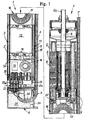
- submersible motor unit comprises, in modular units, an electric drive motor 2, an electrical control device 3 for adjusting the speed and / or torque of the motor 2 and an electrical end plug 4, wherein the motor and the control means in a common, tubular and heat conductive housing 5 are housed.
- the drive motor drives with its shaft 6 to a centrifugal pump (not shown), which is coupled to the protruding end 6a of the shaft 6 in a known manner.
- the Endstecktician 4 is electrically connected to an unshielded cable 7, which extends on the outside of the common housing 5 and is optionally releasably secured thereto by suitable means. Instead of the unit 4, the cable 7 is also electrically connected directly to the device 3.
- the drive motor 2 is, for example, a wet-running motor in the form of a canned motor, so that the rotor of the motor is cooled in a known manner by a liquid.
- the stator 8 of the motor 2 does not flow around the motor liquid directly, but rests against the outer circumference of its sheet metal pact on the common housing 5 and is thus cooled in the usual way by the external liquid into which the submersible motor unit is immersed.
- the drive motor 2 may be an AC motor, in which case the control device 3 is a so-called frequency converter.
- the motor 2 may also be an electronically commutated DC motor, in which case the control device 3 is provided with the appropriate electronic equipment, which is known per se, to control the engine in terms of its speed and / or its torque.
- the control device 3 is provided with the appropriate electronic equipment, which is known per se, to control the engine in terms of its speed and / or its torque.
- Such a motor is in the embodiment according to Fig. 1 shown.
- the control unit 3 used for this motor is designed as a cartridge-shaped unit, which at one end with the drive motor 2, as shown in FIG Fig. 4 , is best seen, and at its other end with the Endsteckiki 4 is electrically plug-connected.
- the cartridge-shaped structural unit has an outer diameter which corresponds to the inner diameter of the common housing 5. After its axial insertion into the common housing, the cartridge-shaped unit comes with its outer peripheral surface 9 on the inner peripheral surface 10 of the common housing 5 to the system, so that the unit can dissipate heat generated in her directly to the common housing.
- the housing of the electrical control device 3 consists of a tubular, heat-conducting, multi-part center unit 11 having in its interior the usual electrical and / or electronic control switching means 12-15, and of two detachably connected to the center unit 11 end units 16 and
- both the motor 2 and the end plug 4 have a plug formation 20 or 21, which are respectively formed to the corresponding plug-in formations 18 and 19 of the device 3, complementary.
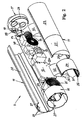
- the center unit 11 consists of several parts 22, 23, 24 and 25, which are predominantly formed as shell parts and have a semicircular cross-section. How out Fig. 2 it can be seen, the shell portion 22 extends over the entire length of the center unit 11, while the other half of the center unit 11 consists of the two shell parts 23 and 24 and at least one metal block 25, which also has a different function in addition to its function as a housing wall , as will become clear.
- the housing parts 22 to 25 are detachably connected to one another via latching means 26, 27 in the form of a groove and a cheek engaging therein.
- end plug-in units 16 and 17 are releasably connected to the center unit 11, for example via rib portions 28, which are frictionally connected to the shell parts 22, 23 and 24, or also via latching means or other types of connection, as will be readily understood by those skilled in the art.
- the center unit 11 is further formed slightly elastic in the radial direction, so that the cartridge-shaped assembly mounted control device 3 is radially flexible and radially inwardly can be slightly compressed. Since the outer diameter of the center unit is slightly larger than the inner diameter of the common housing 5 before inserting the assembly in the common housing, it is ensured that after insertion of the assembly, the outer peripheral surface of the center unit with a certain pressure on the inner peripheral surface of the common housing, to ensure optimum heat transfer.
- the procedure may be such that the shell part 22 has on its circumference a plurality of beads 29 which extend over the length of the shell part 22, as it Fig. 2 below shows.
- the parts 22 to 25 are made of thermally conductive material, such as aluminum.
- the central unit also has a removable in its longitudinal center, removable board 30, which is provided with the usual electrical and / or electronic switching and control means 12 to 15 substantially.
- the parts 23, 24 and 25 may be provided with two diametrically opposed grooves 31 into which the assembled board is inserted. In this way, the entire board is easily interchangeable.
- the heat dissipation means may also comprise at least one metal block whose outer region partially forms the housing of the center unit 11.
- the already mentioned component 25 can take over this function as it is Fig. 2 evident.
- the electronic component 12 of the board generates a lot of heat loss and therefore rests with its entire upper surface 12a on the inner surface 25a of the one- or multi-part metal block 25, so that the loss of heat is discharged directly from the block 25 to the common housing 5.
- the spaced apart position of the heating means 25 and 32 in particular that of approximately disposed in the central region of the central unit 11 metal block 25, protects the drive motor 2 in a particularly effective manner against the heat loss of the electrical and electronic components 12 - 15 and heat effects of sludge in the the submersible unit could be submerged with its lower portion during its operation.
- the end plug unit 4 comprises a housing 33 made of a bottom part 33a and a lid part 33b.
- the bottom part is provided with the plug-in training 21, the electrically conductive sockets are connected to the wires of the external electrical cable 7.
- the housing 33 further includes a side entrance 34 for the outdoor cable.
- the housing is further filled with a potting compound 35 to set the cable 7 positioned kinked in the housing and seal liquid-tight to the outside.
- the bottom part 33a has a support 36 which also ensures a desired deflection radius of the cable 7 entering the housing 33.
- An advantageous embodiment of the unshielded connection cable 7 of the Endstecktician 4 is to form this cable as a flat cable, so that it only slightly increases the outer diameter of the submersible motor unit.
- Fig. 1 shows the common housing 5 is liquid-tightly connected at its motor remote end with a bottom wall 5a, and this bottom wall has a sleeve 5b, in which the plug pins 19a of the plug formation 19 of the electrical control device 3 protrude.
- the Endstecktician 4 is inserted with its Endsteck property 21 in the sleeve 5b and thus establishes the electrical contact with the plug formation 19 of the device 3 ago.
- the bottom part 33a of the unit 4 is provided with a sealing means 37, for example in the form of an elastic plate.
Description
Die Erfindung geht aus von einer Tauchmotoreinheit für eine Kreiselpumpe gemäß dem Oberbegriff des Patentanspruchs 1.The invention relates to a submersible motor unit for a centrifugal pump according to the preamble of
Eine derartige Einheit ist in der
In der
Ein wesentlicher Nachteil dieser vorbekannten Tauchmotoreinheiten besteht darin, daß eine materialgerechte Entsorgung von nicht verwendbaren Tauchmotoreinheiten oder deren Teilen nicht wirtschaftlich durchgeführt werden kann. Es ist ein großer Arbeits- und Zeitaufwand dafür erforderlich, weil die Zerlegung der Einheiten sehr umständlich ist und somit hohe Kosten verursacht. Es findet in verhältnismäßig geringem Umfang nur eine Grobzerlegung, die zu dem mit zahlreichen Trennwerkzeugen durchgeführt werden muß, oder oft auch keine Zerlegung der Einheiten statt. Die anfallenden Grobteile bzw. gesamten Einheiten werden stattdessen in einer Schredderanlage auf das erforderliche Maß zerkleinert. Die zerkleinerte Masse wird nur teilweise wiederverwendet und der Rest zur Entlagerung auf eine Deponie gegeben. Dort können Umweltschäden entstehen, weil die Elektronikteile und die sie umgebenden Feststoffe und Vergußmassen Komponenten enthalten, die mit dem Erdreich oder anderen Stoffen der Deponie umweltschädigende Verbindungen eingehen können. Gesetzliche Vorschriften für die umweltschonende Entsorgung werden aus Kostengründen oft umgangen.A major disadvantage of these known submersible motor units is that a material-appropriate disposal of non-usable submersible motor units or parts thereof can not be carried out economically. It takes a great deal of work and time, because the disassembly of the units is very cumbersome and thus causes high costs. There is a relatively small amount only a coarse separation, which must be done to that with numerous separation tools, or often no disassembly of the units instead. The resulting coarse parts or entire units are instead crushed in a shredder to the required level. The crushed mass is only partially reused and the remainder is given for disposal in a landfill. There environmental damage may occur because the electronic parts and the surrounding solids and potting compounds contain components that can enter into environmentally harmful compounds with the soil or other substances of the landfill. Legal regulations for environmentally friendly disposal are often bypassed for cost reasons.
Der beschriebene Stand der Technik läßt desweiteren auch unter dem Gesichtspunkt der Vermeidung umweltschädigenden Abfalls nur bedingt eine wirtschaftliche Reparatur der Tauchmotoreinheiten zu. Häufig muß für eine Reparatur von Innenteilen der Einheiten das gemeinsame Gehäuse für den Motor und die Steuerungseinrichtung größtenteils und meistens selbst nicht mehr reparabel zerstört werden, so daß hierdurch zusätzliche Kosten durch ein neues gemeinsames Gehäuses entstehen. Abgesehen davon ist auch die Steuerungseinrichtung für den Motor im wesentlichen nicht kostengünstig zu reparieren, weil ihre Elektronikteile aus Stabilitätsgründen für das eigene Gehäuse, das selbst unreparierbar zerstört werden muß, mit Feststoffen und/oder Vergußmassen umgeben sind.Furthermore, the state of the art described only permits limited economic repair of the submersible motor units from the point of view of avoiding environmentally harmful waste. Often, for a repair of internal parts of the units, the common housing for the motor and the control device must be destroyed mostly and not repairable itself, so that thereby additional costs incurred by a new common housing. Apart from that, the control device for the engine is essentially not inexpensive to repair because their electronic parts for stability reasons for their own housing, which itself must be irreparably destroyed, are surrounded by solids and / or potting compounds.
Weiterhin ist auch die Kühlung der elektrischen Steuerungseinrichtung für den Motor nicht zufriedenstellend, weil die von der elektrischen Steuerungseinrichtung und insbesondere von ihren stark wärmerzeugenden Bauteilen anfallende Wärme nur bei hoher Übertemperatur abgeführt werden kann.Furthermore, the cooling of the electrical control device for the engine is not satisfactory, because the costs incurred by the electrical control device and in particular by their highly heat-generating components heat can be dissipated only at high excess temperature.
Die Aufgabe der Erfindung besteht in der Verbesserung einer Tauchmotoreinheit der einleitend angeführten Art dahingehend, daß die Einheit unter dem Gesichtspunkt der Vermeidung einer Umweltbelastung wirtschaftlich entsorgt und repariert werden kann sowie hinsichtlich ihrer Kühlung und Formstabilität verbessert ist.The object of the invention is to improve a submersible motor unit of the kind initially stated in that the unit can be economically disposed of and repaired from the viewpoint of avoiding environmental pollution and improved in terms of cooling and dimensional stability.
Die Lösung dieser Aufgabe ist in dem Patentanspruch 1 angeführt.The solution to this problem is stated in the
Durch die erfindungsgemäße Lösung kann die Tauchmotoreinheit wirtschaftlich entsorgt und repariert werden, denn die Moduleinheiten wie insbesondere der Antriebsmotor und die elektrische Steuerungseinrichtung können schnell mit minimalem Arbeitsaufwand demontiert und ihrerseits auf einfache Weise nach Materialsorten zerlegt und gegebenenfalls nach Auswechseln von schadhaften Bausteinen, Moduleinheiten oder anderen Teilen ebenso zeit- und kostensparend wieder zusammengesetzt werden. Auf diese Weise ist eine verbesserte Reparierbarkeit der Tauchmotoreinheit gewährleistet und bezüglich der Entsorgung brauchen nur diejenigen Teile entsorgt zu werden, die einen nicht behebbaren Schaden aufweisen. Es besteht die Möglichkeit, eine verbesserte Materialtrennung von schadhaften Teilen oder Modulen vorzusehen, so daß aus den ausgewechselten Materialien Alt-Rohmaterial wiedergewonnen werden kann, wodurch primäres Rohmaterial eingespart wird und die Deponie- und Umweltbelastung vermieden oder auf ein Minimum herabgesetzt wird. Im Falle eines schadhaften elektrischen Anschlußkabels entfällt ein zeitraubendes Ab- und Anmontieren des betreffenden Kabels, weil es auf einfache Weise mit der patronenförmigen Baueinheit verbunden ist. Desweiteren ist die Kühlung der elektrischen Steuerungseinrichtung der erfindungsgemäßen Tauchmotoreinheit verbessert, weil deren Verlustwärme von ihrem Gehäuse nun unmittelbar an das gemeinsame Gehäuse und von dort an die zu fördernde, die Einheit umgebende Flüssigkeit abgeführt wird. Schließlich ist durch die Tatsache, daß das Gehäuse der elektrischen Steuerungseinrichtung unmittelbar an dem gemeinsamen Gehäuse anliegt, auch die Stabilität der Tauchmotoreinheit im Bereich der elektrischen Steuerungseinrichtung verbessert, ohne daß das gemeinsame Gehäuse im Abschnitt der elektrischen Steuerungseinrichtung besonders stabil ausgeführt sein muß. Insbesondere ist die Tauchmotoreinheit dadurch biegesteifer und das gemeinsame Gehäuse kann durchgehend für die Moduleinheiten Antriebsmotor und elektrische Steuerungseinrichtung aus einem einzigen Rohrkörper mit relativ dünner Wanddicke bestehen. Außerdem ermöglicht die formstabile patronenförmige Baueinheit ein sicheres Transportieren der in ihr enthaltenen, empfindlichen Elektronikbauteile während der Fertigung der Tauchmotereinheit.The inventive solution, the submersible motor unit can be disposed of and repaired economically, because the modular units such as in particular the drive motor and the electrical control device can be dismantled quickly with minimal effort and in turn easily broken down into types of material and, where appropriate, replaced after replacing defective components, modules or other parts time and cost saving. In this way, an improved repairability of the submersible motor unit is ensured and in terms of disposal, only those parts need to be disposed of that have irreparable damage. It is possible to provide improved material separation of defective parts or modules so that recovered raw materials can be recovered from the replaced materials, thereby saving primary raw material and avoiding or minimizing landfill and environmental impact. In the case of a faulty electrical connection cable eliminates a time-consuming dismantling and Anmontieren the cable in question, because it is connected in a simple way with the cartridge-shaped unit. Furthermore, the cooling of the electrical control device of the submersible motor unit according to the invention is improved, because the heat loss from their housing is now dissipated directly to the common housing and from there to the promotional, surrounding the unit liquid. Finally, by the fact that the housing of the electrical control device rests directly on the common housing, and the stability of the submersible motor unit in the area of the electrical control device improved without the common housing must be made particularly stable in the section of the electrical control device. In particular, the submersible motor unit is thus more rigid and the common housing can consist throughout of the modular units drive motor and electrical control device of a single tubular body with relatively thin wall thickness. In addition, the dimensionally stable cartridge-shaped assembly allows safe transporting in Their contained, sensitive electronic components during the manufacture of the submersible unit.
In vorteilhafter Ausgestaltung der erfindungsgemäßen Tauchmotoreinheit weist diese eine Endsteckeinheit auf, die bereits mit dem Anschlußkabel versehen ist. Dies ermöglicht ein sehr schnelles Auswechseln eines defekten Anschlußkabels.In an advantageous embodiment of the submersible motor unit according to the invention, this has a Endsteckeinheit, which is already provided with the connecting cable. This allows a very quick replacement of a defective connection cable.
In weiterer vorteilhafter Ausgestaltung der erfindungsgemäßen Tauchmotoreinheit umfaßt das Gehäuse der elektrischen Steuerungseinrichtung eine rohrförmige, wärmeleitende Mitteleinheit zur Aufnahme der üblichen elektrischen Steuerschaltmittel und zwei lösbar damit verbundene Endeinheiten mit jeweils einer axialen elektrischen Steckausbildung, wobei die Steckausbildungen beider Endeinheiten in komplementäre elektrische Steckausbildungen des Motors und der Endsteckeinheit eingreifen. Eine derartige Steuerungseinrichtung ist schnell mit angrenzenden Moduleinheiten zu verbinden bzw. davon zu trennen und desweiteren sind die innerhalb des Gehäuses der Steuerungseinrichtung vorgesehenen Steuerschaltmittel zwecks Austausch und/oder Entsorgung schnell zugänglich. Nach dem Austausch von schadhaften Bestandteilen kann das Gehäuse selbst wieder zusammengesetzt werden.In a further advantageous embodiment of the submersible motor unit according to the invention, the housing of the electrical control device comprises a tubular heat-conducting central unit for receiving the usual electrical control switching means and two detachably connected thereto end units each having an axial electrical plug formation, wherein the plug configurations of both end units in complementary electrical plug configurations of the engine and the Engage end plug-in unit. Such a control device is to be quickly connected to adjacent module units or to be separated therefrom and further provided within the housing of the control device control switching means for the purpose of replacement and / or disposal are quickly accessible. After replacement of defective components, the housing itself can be reassembled.
In weiterer Ausbildung umfaßt die eine Gehäuseumfangswand der elektrischen Steuerungseinrichtung bildende Mitteleinheit mindestens ein lösbar befestigtes, im Querschnitt halbkreisförmiges Schalenteil, das sich über die gesamte Länge der Mitteleinheit erstreckt und radial elastisch ausgebildet ist. Die radial elastische Ausbildung des Schalenteiles kann beispielsweise über längsverlaufende Sicken erreicht werden. Auf diese Weise wird eine radial auswärtswirkende Anlagekraft des Gehäuses der Steuerungseinrichtung an das gemeinsame Gehäuse erzielt, wenn die elektrische Steuerungseinrichtung in Form der patronenförmigen Baueinheit in das gemeinsame Gehäuse eingeschoben ist. Hierdurch können bei der Fertigung größere Toleranzen gewählt werden, trotzdem ist sichergestellt, daß das Gehäuse der Steuerungseinrichtung an dem gemeinsamen Gehäuse anliegt, weil das etwas zusammengedrückte Gehäuse der Steuerungseinrichtung nach dem Einschieben in das gemeinsame Gehäuse radial auswärts drückt. So wird auf einfache Weise gewährleistet, daß der Wärmetransport vom Gehäuse der Steuerungseinrichtung auf das gemeinsame Gehäuse optimal stattfindet.In a further embodiment, the housing peripheral wall of the electrical control device forming center unit comprises at least one releasably secured, in cross-section semicircular shell part which extends over the entire length of the center unit and is formed radially elastic. The radially elastic design of the shell part can be achieved for example via longitudinal corrugations. In this way, a radially outwardly acting contact force of the housing of the control device is achieved to the common housing when the electrical control device in the form the cartridge-shaped assembly is inserted into the common housing. As a result, larger tolerances can be selected in the production, but it is ensured that the housing of the control device rests against the common housing, because the slightly compressed housing of the control device presses after insertion into the common housing radially outward. This ensures in a simple manner that the heat transfer from the housing of the control device takes place optimally on the common housing.
In vorteilhafter Weiterbildung der Mitteleinheit umfaßt diese eine sich in ihrer Längsmitte erstreckende, demontierbare Platine, die mit den üblichen elektrischen Schaltmitteln versehen ist, und ferner sind Wärmeableitungsmittel vorgesehen, um die Verlustwärme von den elektronischen Teilen der Platine abzuführen. Die Wärmeableitungsmittel können aus elastisch verformbaren Kissen bestehen, die zwischen der Elektronik und dem Gehäuse der Mitteleinheit eingeklemmt sind. Die Wärmeableitungsmittel können auch aus einem Metallblock bestehen, dessen Außenbereich teilweise das Gehäuse der elektrischen Steuerungseinrichtung mitbildet. Somit können die Wärmeableitungsmittel sparsam eingesetzt werden, weil sie nur dort vorgesehen zu sein brauchen, wo Wärme abgeführt werden muß. Vergußmassen und schüttfähige Feststoffe zum Ausfüllen von Hohlräumen der patronenförmigen Baueinheit sind nicht mehr nötig.In an advantageous embodiment of the center unit, this comprises a extending in its longitudinal center, removable board, which is provided with the usual electrical switching means, and further heat dissipation means are provided to dissipate the heat loss from the electronic parts of the board. The heat dissipation means may consist of elastically deformable pads which are clamped between the electronics and the housing of the center unit. The heat dissipation means can also consist of a metal block whose outer region partially forms the housing of the electrical control device. Thus, the heat dissipation means can be used sparingly because they need only be provided where heat must be dissipated. Casting compounds and free-flowing solids to fill cavities of the cartridge-shaped unit are no longer necessary.
Die Erfindung ist nachstehend anhand eines in der anliegenden Zeichnungen dargestellten Ausführungsbeispieles näher erläutert. Es zeigen
- Fig. 1
- einen axialen Längsschnitt durch das Ausfühungsbeispiel,
- Fig. 2
- eine auseinandergezogene Perspektivansicht auf eine Moduleinheit des Ausführungsbeispiels nach
Fig. 1 , - Fig. 3
- einen Längsschnitt durch eine weitere Moduleinheit des Ausführungsbeispiels nach
Fig. 1 , - Fig. 4
- eine Teildarstellung bei X in
Fig. 1 in vergrößertem Maßstab.
- Fig. 1
- an axial longitudinal section through the Ausfühungsbeispiel,
- Fig. 2
- an exploded perspective view of a modular unit of the embodiment according to
Fig. 1 . - Fig. 3
- a longitudinal section through a further modular unit of the embodiment according to
Fig. 1 . - Fig. 4
- a partial view at X in
Fig. 1 on an enlarged scale.
Die in
Der Antriebsmotor 2 ist beispielsweise ein Naßlaufmotor in Form eines Spaltrohrmotors, so daß der Rotor des Motors in bekannter Weise durch eine Flüssigkeit gekühlt wird. Der Stator 8 des Motors 2 wird dagegen nicht von der Motorflüssigkeit unmittelbar umströmt, sondern liegt mit dem Außenumfang seines Blechpaktes an dem gemeinsamen Gehäuse 5 an und wird somit in üblicher Weise von der Außenflüssigkeit, in welche die Tauchmotoreinheit eingetaucht ist, gekühlt. Weiterhin kann der Antriebsmotor 2 ein Wechselstrommotor sein, wobei dann die Steuerungseinrichtung 3 ein sogenannter Frequenzumrichter ist. Anderseits kann der Motor 2 auch ein elektronisch kommutierter Gleichstrommotor sein, wobei dann die Steuerungseinrichtung 3 mit der entsprechenden elektronischen Ausrüstung, die an sich bekannt ist, versehen ist, um den Motor hinsichtlich seiner Drehzahl und/oder seines Drehmomentes zu steuern. Ein solcher Motor ist in dem Ausführungsbeispiel nach
Die für diesen Motor verwendete Steuerungseinheit 3 ist als patronenförmige Baueinheit ausgebildet, die an ihrem einen Ende mit dem Antriebsmotor 2, wie es in
Gemäß dem gezeigten Ausführungsbeispiel besteht das Gehäuse der elektrischen Steuerungseinrichtung 3 aus einer rohrförmigen, wärmeleitenden, mehrteiligen Mitteleinheit 11, die in ihrem Inneren die üblichen elektrischen und/oder elektronischen Steuerschaltmittel 12 - 15 aufweist, und aus zwei lösbar mit der Mitteleinheit 11 verbundenen Endeinheiten 16 und 17 mit jeweils einer axialen elektrischen Steckausbildung 18 bzw. 19. Um den elektrischen Kontakt der Steuerungseinrichtung 3 mit dem Antriebsmotor 2 und der Endsteckeinheit 4 auf der motorabgewandten Seite der Einrichtung 3 herzustellen, weisen sowohl der Motor 2 als auch die Endsteckeinheit 4 eine Steckausbildung 20 bzw. 21 auf, die jeweils zu den entsprechenden Steckausbildungen 18 bzw. 19 der Einrichtung 3, komplementär ausgebildet sind.According to the embodiment shown, the housing of the
Im einzelnen besteht die Mitteleinheit 11 aus mehreren Teilen 22, 23, 24 und 25, die überwiegend als Schalenteile ausgebildet sind und einen halbkreisförmigen Querschnitt aufweisen. Wie aus
Die Mitteleinheit 11 ist desweiteren in radialer Richtung etwas elastisch ausgebildet, so daß die zur patronenförmigen Baueinheit montierte Steuerungseinrichtung 3 radial flexibel ist und radial einwärts etwas zusammengedrückt werden kann. Da der Außendurchmesser der Mitteleinheit geringfügig größer ist als der Innendurchmesser des gemeinsamen Gehäuses 5 vor dem Einschieben der Baueinheit in das gemeinsame Gehäuse, ist sichergestellt, daß nach dem Einschieben der Baueinheit die Außenumfangsfläche der Mitteleinheit mit einem gewissen Druck an der Innenumfangsfläche des gemeinsamen Gehäuses anliegt, um einen optimalen Wärmeübergang zu gewährleisten.The
Um diese radiale Elastizität der Mitteleinheit 11 zu erreichen, kann so vorgegangen sein, daß das Schalenteil 22 auf seinem Umfang mehrere Sicken 29 aufweist, die sich über die Länge des Schalenteils 22 erstrecken, wie es
Die Teile 22 bis 25 bestehen aus wärmeleitenden Material, beispielsweise aus Aluminium.The
Die Mitteleinheit weist ferner eine sich in ihrer Längsmitte erstrekkende, demontierbare Platine 30 auf, die im wesentlichen mit den üblichen elektrischen und/oder elektronischen Schalt- und Steuermitteln 12 bis 15 versehen ist. Um die Platine 30 in der Mitteleinheit 11 definiert zu halten, können beispielsweise die Teile 23, 24 und 25 mit zwei sich diametral gegenüberliegenden Nuten 31 versehen sein, in welche die bestückte Platine eingeschoben wird. Auf diese Weise ist die gesamte Platine schnell auswechselbar.The central unit also has a removable in its longitudinal center,
Um die von den Schalt- und Steuermitteln 12 bis 15 erzeugte Verlustwärme schnell und gezielt abführen zu können, sind im Inneren der Mitteleinheit 11 bzw. der patronenförmigen Baueinheit z. B. austauchbare Wärmeableitmittel vorgesehen. Diese können beispielsweise aus elastischen Kissen 32 in Segmentform bestehen, die einerseits auf der wärmeerzeugenden Elektronik der Platine oder anderen wärmeerzeugenden Teilen aufliegen und andererseits an der Innenumfangsfläche der Teile 23 und 24 anliegen, derart, daß die Kissen eingeklemmt sind. Zur sicheren Positionierung der elastischen Kissen können diese innenseitig an der Mitteleinheit angeklebt sein.In order to dissipate the heat loss generated by the switching and control means 12 to 15 quickly and selectively, are in the interior of the
Die Wärmeableitmittel können aber auch wenigstens einen Metallblock umfassen, dessen Außenbereich teilweise das Gehäuse der Mitteleinheit 11 mitbildet. Beispielsweise kann das bereits erwähnte Bauteil 25 diese Funktion mitübernehmen, wie es aus
Die voreinander beabstandete Lage der Wärmeheitmittel 25 und 32, insbesondere diejenige des etwa im Mittelbereich der Mitteleinheit 11 angeordneten Metallblocks 25, schützt den Antriebsmotor 2 in besonders wirksamer Weise vor der Verlustwärme der elektrischen und elektronischen Bauteile 12 - 15 und vor Wärmeauswirkungen von Schlamm, in den die Tauchmotoreinheit mit ihrem unteren Bereich während ihres Betriebes eingetaucht sein könnte.The spaced apart position of the heating means 25 and 32, in particular that of approximately disposed in the central region of the
Die Endsteckeinheit 4 umfaßt ein Gehäuse 33 aus einem Bodenteil 33a und einem Deckelteil 33b. Das Bodenteil ist mit der Steckausbildung 21 versehen, deren elektrisch leitende Buchsen mit den Adern des elektrischen Außenkabels 7 verbunden sind. Das Gehäuse 33 weist ferner einen seitlichen Eingang 34 für das Außenkabel auf. Das Gehäuse ist ferner mit einer Vergußmasse 35 ausgegossen, um das Kabel 7 in dem Gehäuse knickfrei positioniert festzulegen und nach außen flüssigkeitsdicht abzudichten.The
Um die knickfreie Lagerung des Anschlußkabels 7 insbesondere während des Ausgießens des Gehäuses 33 mit der Vergußmasse 35 sicherzustellen, weist das Bodenteil 33a eine Stütze 36 auf, die auch einen gewünschten Umlenkradius des in das Gehäuse 33 eintretenden Kabels 7 gewährleistet.In order to ensure the kink-free storage of the connecting
Eine vorteilhafte Ausführungsform des ungeschirmten Anschlußkabels 7 der Endsteckeinheit 4 besteht darin, dieses Kabel als Flachkabel auszubilden, so daß es den Außendurchmesser der Tauchmotoreinheit nur geringfügig vergrößert.An advantageous embodiment of the
Wie es
Claims (12)
- A submersible motor unit for a centrifugal pump, comprising an electrical drive motor (2), electrical control means (3) for setting the rotary speed and/or the torque of the motor, a common heat-conducting housing (5) for the motor and the control means as well as a connection cable (7) electrically connected to the control means, wherein this means (3) is provided on the end-side of the motor, said end-side being away from the pump, characterised in that the electrical control means (3) is formed as a cartridge-like constructional unit which can be inserted into the common housing (5) and which can be electrically plug-connected to the drive motor (2), that the housing (11) of the control means (3) bears with its outer peripheral surface (9) on the inner peripheral surface (10) of the common housing (5) in a manner such that the cartridge-like construction unit may lead away waste heat produced in it, directly to the common housing and that the electrical control means at its end distant to the motor is electrically connected to an unshielded connection cable (7).
- A submersible motor unit according to claim 1, characterised in that the unshielded connection cable (7) is connected to an endplug unit (4) which for its part is plug-connected to the control means (3).
- A submersible motor unit according to claim 1 or 2, characterised in that the housing of the electrical control means comprises a tubular, heat-conducting middle unit (11) for receiving the usual electrical and/or electronic control circuit means (12 - 15), and two end units (16, 17) releasably connected thereto with in each case an axial electrical plug formation (18, 19) and that the plug formations of both end units engage into complementary electrical plug formations (20, 21) of the motor (2) and of the plug unit (3).
- A submersible motor unit according to claim 1, 2 or 3, characterised in that the middle unit (11), forming a housing peripheral wall of the electrical control means (3), comprises at least one releasably fastened shell part (22) which extends over the complete length of the middle unit and is formed radially elastically, in order to achieve a radially outwardly acting bearing force of the middle unit on the common housing (5), given a cartridge-like constructional unit inserted therein.
- A submersible motor unit according to claim 4, characterised in that the radial elastic formation of the shell part (22) consists of beads extending over the length of the shell part (22).
- A submersible motor unit according to claim 3 or 4, characterised in that the middle unit (11) comprises a dismountable circuit board (30) which extends in its longitudinal centre, is provided with the usual electrical and/or electronic control circuit means (12 - 14) and that exchangeable heat dissipating means (32, 25) are provided, in order to lead away the waste heat from the heat producing parts of the circuit board, to the middle unit (11).
- A submersible motor unit according to claim 6, characterised in that the heat dissipating means consist of elastic cushions (32) which lie on the heat producing parts of the circuit board (30) and which are clamped between these parts and the middle unit (11).
- A submersible motor unit according to claim 7, characterised in that the cushion is bonded to the middle unit (11) of the control means (3).
- A submersible motor unit according to claim 6, characterised in that the heat dissipating means comprise at least one metal block (25), whose outer region section partly co-forms the housing of the middle unit (11).
- A submersible motor unit according to one of the claims 2 to 9, characterised in that the end plug unit (4) comprises a housing (33) with a lateral entry (34) for the connection cable (7) and with a cast mass (35) in its inside for the kink-free positioning of the cable therein and for the fluid-tight sealing of the cable in the end plug unit.
- A submersible motor unit according to claim 10, characterised in that a support (36) for the kink-free deflection of the connection cable (7), is provided in the inside of the housing (33) of the end plug unit (4).
- A submersible motor unit according to one of the claims 1 to 11, characterised in that the electrical connection cable (7) is a flat cable.
Applications Claiming Priority (2)
| Application Number | Priority Date | Filing Date | Title |
|---|---|---|---|
| DE19727202 | 1997-06-26 | ||
| DE19727202A DE19727202A1 (en) | 1997-06-26 | 1997-06-26 | Submersible motor unit |
Publications (3)
| Publication Number | Publication Date |
|---|---|
| EP0887907A2 EP0887907A2 (en) | 1998-12-30 |
| EP0887907A3 EP0887907A3 (en) | 2000-04-26 |
| EP0887907B1 true EP0887907B1 (en) | 2011-03-09 |
Family
ID=7833749
Family Applications (1)
| Application Number | Title | Priority Date | Filing Date |
|---|---|---|---|
| EP98110878A Expired - Lifetime EP0887907B1 (en) | 1997-06-26 | 1998-06-15 | Submersible motor unit |
Country Status (3)
| Country | Link |
|---|---|
| US (1) | US6022196A (en) |
| EP (1) | EP0887907B1 (en) |
| DE (2) | DE19727202A1 (en) |
Cited By (1)
| Publication number | Priority date | Publication date | Assignee | Title |
|---|---|---|---|---|
| DE102016009400A1 (en) * | 2016-08-02 | 2018-02-08 | Hydac Fluidtechnik Gmbh | Method for producing a splash-proof electrical cable connection |
Families Citing this family (21)
| Publication number | Priority date | Publication date | Assignee | Title |
|---|---|---|---|---|
| FR2790519B1 (en) * | 1999-03-05 | 2001-05-18 | Ksb Sa | SUBMERSIBLE MOTOR PUMP GROUP WITH INTEGRATED STARTING CIRCUIT |
| DE10010961A1 (en) | 2000-03-06 | 2001-09-20 | Grundfos As | Motor assembly for a submersible pump unit |
| DE10010919A1 (en) * | 2000-03-06 | 2001-09-20 | Grundfos As | Frequency regulator for electric motor has electrical connections for intermediate electronic circuit component and regulating electronic circuit component provided by stamped out sheet metal elements |
| IT1315419B1 (en) * | 2000-04-11 | 2003-02-10 | Coverco Spa | STRUCTURE OF SINGLE-PHASE MOTOR PARTICULARLY FOR SUBMERSIBLE PUMPS. |
| US6398521B1 (en) | 2001-01-30 | 2002-06-04 | Sta-Rite Industries, Inc. | Adapter for motor and fluid pump |
| FR2841702B1 (en) * | 2002-06-27 | 2004-09-10 | Somfy | ELECTRIC ACTUATOR PROVIDED WITH A CONNECTING PART |
| US20060034717A1 (en) * | 2004-08-13 | 2006-02-16 | Joseph Castellone | Wet rotor circulators |
| US7091638B2 (en) * | 2004-10-14 | 2006-08-15 | Pentair Pump Group, Inc. | Modular end bell construction for a submersible motor unit |
| SE529217C2 (en) * | 2005-05-20 | 2007-06-05 | Atlas Copco Tools Ab | Torque dependent release clutch for a screwdriver |
| JP4569428B2 (en) * | 2005-09-12 | 2010-10-27 | 株式会社デンソー | Liquid crystal display |
| FR2891413B1 (en) * | 2005-09-28 | 2008-02-08 | Fp2X Groupement D Interet Econ | TUBULAR ELECTRIC MOTOR DEVICE |
| FR2891415B1 (en) * | 2005-09-28 | 2011-08-12 | Fp2X | ELECTRONIC CONTROL ASSEMBLY FOR A TUBULAR ELECTRIC MOTOR DEVICE |
| DE102006036493A1 (en) * | 2006-08-04 | 2008-02-21 | Oerlikon Leybold Vacuum Gmbh | vacuum pump |
| US20080286134A1 (en) * | 2007-05-16 | 2008-11-20 | Steven Regalado | Submersible pumping systems and methods for deep well applications |
| US8760089B2 (en) * | 2009-11-30 | 2014-06-24 | Franklin Electric Company, Inc. | Variable speed drive system |
| DE102010026231A1 (en) * | 2010-07-06 | 2012-01-12 | Andritz Ritz Gmbh | Underwater propulsion unit for offshore use with high voltage direct current power supply and underwater propulsion system |
| US9780716B2 (en) | 2010-11-19 | 2017-10-03 | General Electric Company | High power-density, high back emf permanent magnet machine and method of making same |
| US8664903B2 (en) | 2011-06-27 | 2014-03-04 | Franklin Electric Company, Inc. | Adaptive flux control drive |
| RU2521532C2 (en) * | 2012-08-21 | 2014-06-27 | Общество с ограниченной ответственностью "Нефтегазовые космические технологии" | Borehole electronic unit for borehole electrically driven pump |
| DE102014116242A1 (en) * | 2014-11-07 | 2016-05-12 | Uts Biogastechnik Gmbh | Stirring device for a fermenter of a biogas plant |
| AU2016318161B2 (en) | 2015-09-03 | 2019-06-06 | Fluid Handling Llc | Submersible pump motor housing for improving the serviceability of submersible pumps |
Family Cites Families (11)
| Publication number | Priority date | Publication date | Assignee | Title |
|---|---|---|---|---|
| DE3642727A1 (en) | 1986-12-13 | 1988-06-23 | Grundfos Int | Underwater motor-driven pump |
| US4930997A (en) * | 1987-08-19 | 1990-06-05 | Bennett Alan N | Portable medical suction device |
| US5025185A (en) * | 1988-06-07 | 1991-06-18 | Aquaria, Inc. | Bubble trap for epoxy sealant in a submersible electric motor |
| DE3820003A1 (en) * | 1988-06-11 | 1989-12-21 | Grundfos Int | SUBMERSIBLE PUMP UNIT |
| DE3828512A1 (en) * | 1988-08-23 | 1990-03-08 | Grundfos Int | SUBMERSIBLE PUMP UNIT |
| JPH078877Y2 (en) * | 1989-03-07 | 1995-03-06 | 株式会社荏原製作所 | Submersible pump controller |
| US5028212A (en) * | 1989-09-26 | 1991-07-02 | Brophey Robert W | Method and apparatus for removal of floating immiscible liquids |
| DE4120665A1 (en) * | 1991-06-22 | 1992-12-24 | Teves Gmbh Alfred | ELECTRICALLY DRIVEN HYDRAULIC PUMP |
| DE4317497A1 (en) * | 1993-05-26 | 1994-12-01 | Kabelmetal Electro Gmbh | Method for the production of longitudinally watertight (waterproof) cables |
| DE19620901C1 (en) * | 1996-05-23 | 1997-08-21 | Grundfos As | Immersion motor for circulation pump |
| US5763973A (en) * | 1996-10-30 | 1998-06-09 | Imo Industries, Inc. | Composite barrier can for a magnetic coupling |
-
1997
- 1997-06-26 DE DE19727202A patent/DE19727202A1/en not_active Withdrawn
-
1998
- 1998-06-15 EP EP98110878A patent/EP0887907B1/en not_active Expired - Lifetime
- 1998-06-15 DE DE59814484T patent/DE59814484D1/en not_active Expired - Lifetime
- 1998-06-23 US US09/102,783 patent/US6022196A/en not_active Expired - Lifetime
Non-Patent Citations (1)
| Title |
|---|
| None * |
Cited By (1)
| Publication number | Priority date | Publication date | Assignee | Title |
|---|---|---|---|---|
| DE102016009400A1 (en) * | 2016-08-02 | 2018-02-08 | Hydac Fluidtechnik Gmbh | Method for producing a splash-proof electrical cable connection |
Also Published As
| Publication number | Publication date |
|---|---|
| EP0887907A3 (en) | 2000-04-26 |
| DE59814484D1 (en) | 2011-04-21 |
| DE19727202A1 (en) | 1999-01-28 |
| EP0887907A2 (en) | 1998-12-30 |
| US6022196A (en) | 2000-02-08 |
Similar Documents
| Publication | Publication Date | Title |
|---|---|---|
| EP0887907B1 (en) | Submersible motor unit | |
| DE3642724C2 (en) | ||
| DE4243044C2 (en) | Inverter-motor combination | |
| EP3631966B1 (en) | Motor vehicle and inverter device for a motor vehicle | |
| EP2607707B1 (en) | Electric motor | |
| EP3615364B1 (en) | Rechargeable battery arrangement | |
| DE10326297A1 (en) | engine | |
| DE4120665A1 (en) | ELECTRICALLY DRIVEN HYDRAULIC PUMP | |
| EP2270961A2 (en) | Electric motor with frequency converter | |
| DE102004013578A1 (en) | Drive system with electrical power devices | |
| EP2072828A1 (en) | Wet-running centrifugal pump | |
| WO2013092534A1 (en) | Electric motor | |
| AT10549U1 (en) | FROM A COMBUSTION ENGINE AND A GENERATOR POWER GENERATOR | |
| WO2018041401A1 (en) | Motor pump device | |
| EP2398132A1 (en) | Pump power unit | |
| DE10223529B4 (en) | Motor with an electronic control unit and method of manufacturing the same | |
| EP2750268B1 (en) | Pump power unit | |
| DE3122655A1 (en) | "ACTUAL VALUE DEVICE" | |
| EP3232546A1 (en) | Centrifugal pump motor | |
| WO2013092317A2 (en) | Electric motor | |
| DE102007057839A1 (en) | Electric motor for motor vehicle, has central motor support module with main plate and preinstalled modules | |
| DE102019109693B4 (en) | Drive unit with an electric machine and with a control unit | |
| DE102004037079A1 (en) | Power converter for use in electrical power unit, has power converter housing with cooling fin, and including axial front wall, where converter is provided for axial attachment in electrical machine | |
| EP1104079A2 (en) | Electric motor, in particular for a centrifugal pump | |
| DE19709778A1 (en) | Electric motor-pump unit for vehicle braking system |
Legal Events
| Date | Code | Title | Description |
|---|---|---|---|
| PUAI | Public reference made under article 153(3) epc to a published international application that has entered the european phase |
Free format text: ORIGINAL CODE: 0009012 |
|
| AK | Designated contracting states |
Kind code of ref document: A2 Designated state(s): DE FR GB IT |
|
| AX | Request for extension of the european patent |
Free format text: AL;LT;LV;MK;RO;SI |
|
| PUAL | Search report despatched |
Free format text: ORIGINAL CODE: 0009013 |
|
| AK | Designated contracting states |
Kind code of ref document: A3 Designated state(s): AT BE CH CY DE DK ES FI FR GB GR IE IT LI LU MC NL PT SE |
|
| AX | Request for extension of the european patent |
Free format text: AL;LT;LV;MK;RO;SI |
|
| RIC1 | Information provided on ipc code assigned before grant |
Free format text: 7H 02K 5/132 A, 7H 02K 11/04 B, 7H 02K 5/22 B |
|
| 17P | Request for examination filed |
Effective date: 20000803 |
|
| AKX | Designation fees paid |
Free format text: DE FR GB IT |
|
| 17Q | First examination report despatched |
Effective date: 20061116 |
|
| GRAP | Despatch of communication of intention to grant a patent |
Free format text: ORIGINAL CODE: EPIDOSNIGR1 |
|
| GRAS | Grant fee paid |
Free format text: ORIGINAL CODE: EPIDOSNIGR3 |
|
| GRAA | (expected) grant |
Free format text: ORIGINAL CODE: 0009210 |
|
| AK | Designated contracting states |
Kind code of ref document: B1 Designated state(s): DE FR GB IT |
|
| REG | Reference to a national code |
Ref country code: GB Ref legal event code: FG4D Free format text: NOT ENGLISH |
|
| REF | Corresponds to: |
Ref document number: 59814484 Country of ref document: DE Date of ref document: 20110421 Kind code of ref document: P |
|
| REG | Reference to a national code |
Ref country code: DE Ref legal event code: R096 Ref document number: 59814484 Country of ref document: DE Effective date: 20110421 |
|
| PLBE | No opposition filed within time limit |
Free format text: ORIGINAL CODE: 0009261 |
|
| STAA | Information on the status of an ep patent application or granted ep patent |
Free format text: STATUS: NO OPPOSITION FILED WITHIN TIME LIMIT |
|
| 26N | No opposition filed |
Effective date: 20111212 |
|
| REG | Reference to a national code |
Ref country code: DE Ref legal event code: R097 Ref document number: 59814484 Country of ref document: DE Effective date: 20111212 |
|
| REG | Reference to a national code |
Ref country code: FR Ref legal event code: PLFP Year of fee payment: 19 |
|
| PGFP | Annual fee paid to national office [announced via postgrant information from national office to epo] |
Ref country code: DE Payment date: 20160622 Year of fee payment: 19 Ref country code: GB Payment date: 20160506 Year of fee payment: 19 |
|
| PGFP | Annual fee paid to national office [announced via postgrant information from national office to epo] |
Ref country code: IT Payment date: 20160504 Year of fee payment: 19 Ref country code: FR Payment date: 20160422 Year of fee payment: 19 |
|
| REG | Reference to a national code |
Ref country code: FR Ref legal event code: PLFP Year of fee payment: 20 |
|
| REG | Reference to a national code |
Ref country code: DE Ref legal event code: R119 Ref document number: 59814484 Country of ref document: DE |
|
| GBPC | Gb: european patent ceased through non-payment of renewal fee |
Effective date: 20170615 |
|
| REG | Reference to a national code |
Ref country code: FR Ref legal event code: ST Effective date: 20180228 |
|
| PG25 | Lapsed in a contracting state [announced via postgrant information from national office to epo] |
Ref country code: GB Free format text: LAPSE BECAUSE OF NON-PAYMENT OF DUE FEES Effective date: 20170615 Ref country code: DE Free format text: LAPSE BECAUSE OF NON-PAYMENT OF DUE FEES Effective date: 20180103 |
|
| PG25 | Lapsed in a contracting state [announced via postgrant information from national office to epo] |
Ref country code: FR Free format text: LAPSE BECAUSE OF NON-PAYMENT OF DUE FEES Effective date: 20170630 Ref country code: IT Free format text: LAPSE BECAUSE OF NON-PAYMENT OF DUE FEES Effective date: 20170615 |