EP0887828A2 - Electromagnetic relay used in a telephone exchange or the like and contact spring assembly for the electromagnetic relay - Google Patents
Electromagnetic relay used in a telephone exchange or the like and contact spring assembly for the electromagnetic relay Download PDFInfo
- Publication number
- EP0887828A2 EP0887828A2 EP98302299A EP98302299A EP0887828A2 EP 0887828 A2 EP0887828 A2 EP 0887828A2 EP 98302299 A EP98302299 A EP 98302299A EP 98302299 A EP98302299 A EP 98302299A EP 0887828 A2 EP0887828 A2 EP 0887828A2
- Authority
- EP
- European Patent Office
- Prior art keywords
- contact spring
- armature
- electromagnetic relay
- movable
- sets
- Prior art date
- Legal status (The legal status is an assumption and is not a legal conclusion. Google has not performed a legal analysis and makes no representation as to the accuracy of the status listed.)
- Granted
Links
Images


Classifications
-
- H—ELECTRICITY
- H01—ELECTRIC ELEMENTS
- H01H—ELECTRIC SWITCHES; RELAYS; SELECTORS; EMERGENCY PROTECTIVE DEVICES
- H01H50/00—Details of electromagnetic relays
- H01H50/54—Contact arrangements
- H01H50/60—Contact arrangements moving contact being rigidly combined with movable part of magnetic circuit
-
- H—ELECTRICITY
- H01—ELECTRIC ELEMENTS
- H01H—ELECTRIC SWITCHES; RELAYS; SELECTORS; EMERGENCY PROTECTIVE DEVICES
- H01H50/00—Details of electromagnetic relays
- H01H50/54—Contact arrangements
- H01H50/548—Contact arrangements for miniaturised relays
-
- H—ELECTRICITY
- H01—ELECTRIC ELEMENTS
- H01H—ELECTRIC SWITCHES; RELAYS; SELECTORS; EMERGENCY PROTECTIVE DEVICES
- H01H50/00—Details of electromagnetic relays
- H01H50/16—Magnetic circuit arrangements
- H01H50/18—Movable parts of magnetic circuits, e.g. armature
- H01H50/24—Parts rotatable or rockable outside coil
- H01H50/28—Parts movable due to bending of a blade spring or reed
Definitions
- the present invention relates to an electromagnetic relay and a contact spring assembly for the electromagnetic relay, and more particularly, to an electromagnetic relay used in a telephone exchange or the like and a contact spring assembly for the electromagnetic relay.
- the telephone exchange for example, three electromagnetic relays are provided for each subscriber circuit in the exchange, of which two electromagnetic relays control a connection operation of a test circuit to switch the mode between normal operation mode and test mode.
- the remaining electromagnetic relay is used for dial pulse transmission.
- all the connections on the three electromagnetic relays are reversed from that of the normal operation mode and testing is performed by the test circuit.
- the testing by the test circuit is, for example, performed once a day or once every few days, to check the impedance, connection, etc. from the exchange to the subscriber.
- An object of the present invention is to provide an electromagnetic relay that can be assembled simply and with high accuracy, and that is suited to size and power consumption reductions. It is also an object of the present invention to provide a contact spring assembly for an electromagnetic relay, suitable for use with a test circuit of a telephone exchange, and to reduce the size, cost, and power consumption of the exchange by reducing the number of electromagnetic relays used.
- a contact spring assembly for an electromagnetic relay comprising an armature centrally placed in the contact spring assembly; a plurality of movable contact springs each formed integrally with a corresponding hinge spring and disposed on both sides of the armature in such a manner as to extend in parallel along a longitudinal direction of the armature; and a plurality of transfer contact spring sets and a plurality of make contact spring sets constructed from the movable contact springs.
- the transfer contact spring sets and the make contact spring sets may be disposed, as two sets, on each side of the armature in such a manner as to be symmetrical about the armature.
- the contact spring assembly may be used to control a connection operation of a test circuit in a telephone exchange.
- an electromagnetic relay comprising a stationary contact spring block provided with a plurality of stationary contacts; a movable contact spring block provided with a plurality of movable contacts corresponding to the plurality of stationary contacts, and comprising an armature centrally placed in the contact spring assembly, a plurality of movable contact springs each formed integrally with a corresponding hinge spring and disposed on both sides of the armature in such a manner as to extend in parallel along a longitudinal direction of the armature, and a plurality of transfer contact spring sets constructed from the movable contact springs; and an electromagnet block for controlling an attraction of the armature and thereby controlling connections between the movable contacts and the stationary contacts corresponding to the movable contacts.
- the transfer contact spring sets may be disposed on each side of the armature in such a manner as to be symmetrical about the armature.
- an electromagnetic relay comprising a stationary contact spring block provided with a plurality of stationary contacts; a movable contact spring block provided with a plurality of movable contacts corresponding to the plurality of stationary contacts, and comprising an armature centrally placed in the contact spring assembly, a plurality of movable contact springs each formed integrally with a corresponding hinge spring and disposed on both sides of the armature in such a manner as to extend in parallel along a longitudinal direction of the armature, and a plurality of make contact spring sets constructed from the movable contact springs; and an electromagnet block for controlling an attraction of the armature and thereby controlling connections between the movable contacts and the stationary contacts corresponding to the movable contacts.
- the make contact spring sets may be disposed on each side of the armature in such a manner as to be symmetrical about the armature.
- an electromagnetic relay comprising a stationary contact spring block provided with a plurality of stationary contacts; a movable contact spring block provided with a plurality of movable contacts corresponding to the plurality of stationary contacts, and comprising an armature centrally placed in the contact spring assembly, a plurality of movable contact springs each formed integrally with a corresponding hinge spring and disposed on both sides of the armature in such a manner as to extend in parallel along a longitudinal direction of the armature, and a plurality of transfer contact spring sets and a plurality of make contact spring sets constructed from the movable contact springs; and an electromagnet block for controlling an attraction of the armature and thereby controlling connections between the movable contacts and the stationary contacts corresponding to the movable contacts.
- the transfer contact spring sets and the make contact spring sets may be disposed, as two sets, on each side of the armature in such a manner as to be symmetrical about the armature.
- each hinge spring on the movable contact spring block may be welded to a corresponding spring terminal on the stationary contact spring block, and the movable contact spring block may be attached to the stationary contact spring block by utilizing the resilience of each of the hinge springs.
- each hinge spring may have an open-end slit portion, and the open-ended slit portion may be welded to the corresponding spring terminal by laser welding.
- the electromagnetic relay may be used to control a connection operation of a test circuit in a telephone exchange, and the connection control of the test circuit may be performed using one electromagnetic relay.
- Lightning surge protection is traditionally required for subscriber circuits in telephone exchanges. Since implementing this lightning surge protection capability with semiconductor devices is extremely costly, electromagnetic relays are used in subscriber circuits in telephone exchanges. This situation is expected to continue into the future.
- Figure 1 is a circuit diagram showing a typical configuration of a subscriber circuit in a telephone exchange.
- reference character J is a subscriber
- B1 is a power supply
- O is an overvoltage protection block for protecting the subscriber circuit from large voltages due to lightning and the like
- R is a ringing circuit (dial pulse output circuit) for sending a ringing tone to the subscriber J
- C is a codec for performing conversion between voice signal and PCM signal
- H is a hybrid for performing two-wire to four-wire conversion
- TST is a test circuit.
- two overvoltage protection blocks O are provided, one each at the primary and secondary sides.
- the power supply B1 is connected to communication lines L1 and L2, and supplies a constant current to the communication lines L1 and L2 when the subscriber J goes off-hook. At this time, the power supply B1 presents a high impedance to the AC signal (voice signal) so that the signal is not attenuated.
- Three electromagnetic relays 101, 102, and 103 are provided for each subscriber circuit in the exchange, of which the two electromagnetic relays 101 and 102 control the connection of the test circuit TST to switch the mode between normal operation mode and test mode.
- the remaining electromagnetic relay 103 is used for dial pulse transmission.
- Figure 1 shows the condition in the normal operation mode (test off); in the test mode (test on), all the connections on the electromagnetic relays 101, 102, and 103 are reversed and testing is performed by the test circuit TST.
- the testing by the test circuit TST is performed once a day or once every few days, to check the impedance, connection, etc. from the exchange to the subscriber J.
- Figures 2A to 2C are diagrams showing one example of a prior art electromagnetic relay construction that uses a single movable contact spring.
- Figures 3A to 3B are diagrams showing one example of a prior art electromagnetic relay construction that uses a plurality of (four) movable contact springs.
- Figure 2A shows a plan view
- Figure 2B a front view
- Figure 2C a side view
- Figure 3A shows a front view and Figure 3B a side view.
- the prior art electromagnetic relays comprise such discrete parts as a movable spring 200, a stationary spring 201, an array of externally extending terminal leads 202, an armature 203, and an electromagnet block (iron core 204, coil bobbin 205, wire 206, and yoke 207), which are individually assembled onto a base 208.
- Such construction has not only hindered the improvement of assembly accuracy but also required increased man-hours for assembly.
- reference numeral 200a indicates a movable contact, 201a a stationary contact, 209 a coil terminal, 210 a cover, 211 a lead wire, 212 a spring, and 213 a movable spring mold.
- the movable spring 200 in the prior art electromagnetic relay for example, of a single pole type is welded directly to the armature 203, etc.
- the movable spring mold 213 is used and, in addition, a return spring for forced restoring, such as the spring 212, is used. This has resulted in increased complexity of assembly.
- test circuit TST test circuit TST
- three electromagnetic relays two for the test circuit
- these electromagnetic relays have to be provided for each subscriber circuit, such a configuration has been a major factor working against the reduction of the size and cost of the exchange.
- cost involved in the provision of these electromagnetic relays such a configuration has impeded the effort to reduce the cost of the telephone exchange.
- Figures 4A and 4B are diagrams showing a test switching circuit in the subscriber circuit of Figure 1 and an equivalent circuit for the same.
- Figure 4A corresponds to the configuration of Figure 1
- Figure 4B concerns the configuration applied to the electromagnetic relay according to the embodiment of the invention hereinafter described.
- three electromagnetic relays 101, 102, and 103 are provided for each subscriber circuit in the conventional exchange, of which the two electromagnetic relays 101 and 102, each with two transfer contact spring sets, are used to control the connection of the test circuit TST, and the remaining electromagnetic relay 103 is used to control dial pulse transmission.
- the equivalent circuit shown in Figure 4B is applied to the electromagnetic relay and the contact spring assembly for the electromagnetic relay according to the present invention. More specifically, in the embodiment hereinafter described, the two electromagnetic relays 101 and 102 are combined into one electromagnetic relay 100, with a pair of make contact spring sets provided in place of the two-transfer electromagnetic relay 101 and a pair of transfer contact spring sets in place of the two-transfer electromagnetic relay 102 to construct the contact spring assembly for the electromagnetic relay.
- Figures 4A and 4B show the condition in the normal operation mode (test off); in the test mode (test on), all the connections on the electromagnetic relays, 101, 102, and 103, and 100 and 103, are reversed and testing is performed by the test circuit TST.
- the make contacts on the electromagnetic relay 100 are set to the break side in the normal operation mode, and are switched to the make side in the test mode.
- the testing by the test circuit TST is performed once a day or once every few days, to check the impedance, connection, etc. from the exchange to the subscriber J.
- the two electromagnetic relays 101 and 102 used for example, in each subscriber circuit in the telephone exchange are combined into one electromagnetic relay 100 wherein the eight contacts on the two electromagnetic relays 101 and 102, each relay having a pair of transfer contact spring sets), are replaced by the six contacts on the electromagnetic relay 100 having a pair of make contact spring sets and a pair of transfer contact spring sets.
- This permits reductions in the size, cost, and power consumption of the electromagnetic relay and the telephone exchange, etc. using the electromagnetic relay.
- by reducing the number of contacts from eight to six it becomes possible to reduce the amount of noble metal used for the contacts, which contributes to further reducing the cost.
- Figure 5 is an exploded perspective view showing one embodiment of the electromagnetic relay according to the present invention
- Figure 6 is an exploded perspective view (a perspective view showing a portion broken away) of an electromagnet block in the electromagnetic relay of the present invention
- Figure 7 is a perspective view showing the condition of the electromagnetic relay of the present invention, as viewed from the terminal lead side, when the electromagnet block is fitted into a stationary contact spring block
- Figure 8 is a perspective view showing the condition of the electromagnetic relay of the present invention, as viewed from the terminal lead side, after an insulating material has been filled into the gap between the stationary contact spring block and the electromagnet block.
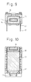
- Figure 9 is a cross-sectional view taken along line A-A in the exploded perspective view of Figure 5
- Figure 10 is a cross-sectional view taken along line B-B in the exploded perspective view of Figure 5.
- Figure 11 is an enlarged perspective view showing the movable contact spring block and stationary contact spring block in the electromagnetic relay of the present invention.
- the electromagnetic relay of the present embodiment comprises the electromagnet block 10, movable contact spring block 20, stationary contact spring block (box-shaped stationary contact spring block) 30, and a case (not shown).
- the electromagnet block 10 is constructed by insert-molding an iron core 17, bent in an L shape, and coil terminals 13 integrally with a bobbin mold 11 having flanges 12 and 12 on both sides thereof, by winding wire 15 around the body 14 of the bobbin mold 11, and by fitting a recessed joint portion 16b formed in an L-shaped magnetic pole piece 16 onto a protruding end portion 17a of the L-shaped iron core 17 inserted in a center hole 14a formed through the body 14, the other portion of the magnetic pole piece 16 being formed as a magnetic pole face 16a.
- the wound wire 15 is connected via the coil terminals 13 to coil terminals 33 on the stationary contact spring block 30.
- the movable contact spring block 20 in the electromagnetic relay of the present embodiment comprises a centrally placed armature 21, and a plurality of movable springs 24, each acting as both a hinge spring 22 and a movable contact spring 23, that are placed on both sides of the armature 21 and extend along the longitudinal direction thereof; the armature 21 and the movable springs 24 are fabricated as a single unit using a molding material 26.
- the hinge springs 22 are positioned on the wider end side of the armature 21 integrally molded with the movable springs 24, and each hinge spring 22 has a dog-legged hinge portion 22b.
- the armature 21 is formed by stamping a plate-like magnetic material; the free end portion 21a of the armature 21 is disposed opposite the pole face 16a of the L-shaped magnetic pole piece 16 and one face at the other end of the armature 21 is contacted with an iron core hinge portion 17a of the L-shaped iron core 17, the portion supported by the iron core hinge portion 17a being the wider end portion 21b.
- the stationary contact spring block (box-shaped stationary contact spring block) 30 is formed in the shape of a rectangular parallelepipedic, hollow box.
- the externally extending movable contact spring terminals 31, stationary contact spring terminals 32, and coil terminals 33 are formed, in an integral fashion, the externally extending movable contact spring terminals 31, stationary contact spring terminals 32, and coil terminals 33.
- the stationary contact springs 34 of the externally extending stationary contact spring terminals 32 are linked integrally with the stationary contact spring terminal 32 side and are positioned opposite the movable contact springs 23; an appropriate bend is provided so as to form transfer contact sets (make and break contact sets) in accordance with the contact spring sets of the stationary contacts 34a.
- a pair of transfer contact spring sets and a pair of make contact spring sets are formed to correspond with those in the equivalent circuit shown in Figure 4B.
- These transfer contact spring sets and make contact spring sets are provided symmetrically about the armature 21.
- the above-described mechanical components are unitized by mold forming to construct the electromagnet block 10, movable contact spring block 20, and stationary contact spring block 30.
- the electromagnet block 10 is inserted into the insertion holes 38 and 39 in the cavity of the stationary contact spring block 30 from the externally extending terminal side (the underside) thereof, as shown in the exploded perspective view of Figure 5, and fixed in position. More specifically, the iron core hinge portion 17a of the iron core 17 is inserted through the insertion hole 38 formed in the cavity of the stationary contact spring block 30, and the pole face 16a of the pole piece 16 is inserted through the insertion hole 39 in such a manner as to protrude upwardly in Figure 5.
- the movable contact spring block 20 is mounted onto the stationary contact spring block 30, and the free end portion 22a of each of the dog-legged hinge springs 22 is fastened rigidly to the corresponding spring terminal 37 provided on the stationary contact spring block 30.
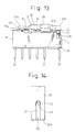
- Figure 12 is a diagram showing how the movable contact spring block is fitted onto the stationary contact spring block in the electromagnetic relay of the present invention
- Figure 13 is a diagram showing the condition of the electromagnetic relay of the present invention in which the movable contact spring block and the stationary contact spring block are fastened together.
- Figure 14 is a diagram for explaining how the hinge spring is welded to the spring terminal in the electromagnetic relay of Figure 13.
- the movable contact spring block 20 is mounted on the stationary contact spring block 30 by placing the free end portions 22a of the hinge springs 22 into intimate contact with the spring terminals 37 linked integrally with the externally extending movable contact spring terminals 31, and by welding them together by a laser or the like.
- each hinge spring 22 (hinge portion 22b) on the movable contact spring block 20 has an open-ended slit portion 22c; by shining a laser beam LB on the upper end portion of the slit portion 22c, the hinge spring 22 and the spring terminal 37 are joined together with a molten portion MP, and by utilizing the resilience of each hinge spring 22 (hinge portion 22b), the movable contact spring block 20 is held to the stationary contact spring block 30.
- the springs on the free end side of the armature 21 opposite from the hinge springs 22 act as the movable springs 24 (movable contact springs 23).
- each hinge spring 22 has a free end portion 22a of each hinge spring 22 .
- the reasons that the open-ended slit portion 22c is formed in the free end portion 22a of each hinge spring 22 are that it is easier to remove chips (pieces separated by cutting) when the spring is stamped by a stamping die, and that the curved end of the slit portion serves to increase the area of the molten portion MP to be welded by the laser beam LB focused into a spot.
- the fastening between the free end portion 22a of the hinge spring 22 and the spring terminal 37 can be accomplished not only by laser welding but also by various other techniques.
- the electromagnetic relay comprises the centrally placed armature, movable contact springs formed integrally with the hinge springs and disposed on both sides of the armature in such a manner as to extend in parallel along the longitudinal direction thereof, and a plurality of transfer contact spring sets and a plurality of make contact spring sets constructed from the movable contact springs; the electromagnetic relay thus constructed can be assembled simply and with high accuracy, and is suited to size and power consumption reductions.
- the present invention provides a contact spring assembly, for the electromagnetic relay, that is suitable for use with a test circuit of a telephone exchange, and that permits a reduction in the number of electromagnetic relays used, thereby achieving reductions in the size, cost, and power consumption of the telephone exchange.
Landscapes
- Physics & Mathematics (AREA)
- Electromagnetism (AREA)
- Electromagnets (AREA)
- Monitoring And Testing Of Exchanges (AREA)
- Interface Circuits In Exchanges (AREA)
- Telephone Set Structure (AREA)
Abstract
Description
Claims (12)
- A contact spring assembly for an electromagnetic relay, comprising:an armature (21) centrally placed in said contact spring assembly;a plurality of movable contact springs (23) each formed integrally with a corresponding hinge spring (22) and disposed on both sides of said armature (21) in such a manner as to extend in parallel along a longitudinal direction of said armature (21); anda plurality of transfer contact spring sets and a plurality of make contact spring sets constructed from said movable contact springs (23).
- A contact spring assembly for an electromagnetic relay as claimed in claim 1, wherein said transfer contact spring sets and said make contact spring sets are disposed, as two sets, on each side of said armature (21) in such a manner as to be symmetrical about said armature (21).
- A contact spring assembly for an electromagnetic relay as claimed in claim 1 or 2, wherein said contact spring assembly is used to control a connection operation of a test circuit in a telephone exchange.
- An electromagnetic relay comprising:a stationary contact spring block (30) provided with a plurality of stationary contacts (34a);a movable contact spring block (20) provided with a plurality of movable contacts (23a) corresponding to said plurality of stationary contacts (34a), and comprising an armature (21) centrally placed in said contact spring assembly, a plurality of movable contact springs (23) each formed integrally with a corresponding hinge spring (22) and disposed on both sides of said armature (21) in such a manner as to extend in parallel along a longitudinal direction of said armature (21), and a plurality of transfer contact spring sets constructed from said movable contact springs (23); andan electromagnet block (10) for controlling an attraction of said armature (21) and thereby controlling connections between said movable contacts (23a) and said stationary contacts (34a) corresponding to said movable contacts (23a).
- An electromagnetic relay as claimed in claim 4, wherein said transfer contact spring sets are disposed on each side of said armature (21) in such a manner as to be symmetrical about said armature (21).
- An electromagnetic relay comprising:a stationary contact spring block (30) provided with a plurality of stationary contacts (34a);a movable contact spring block (20) provided with a plurality of movable contacts (23a) corresponding to said plurality of stationary contacts (34a), and comprising an armature (21) centrally placed in said contact spring assembly, a plurality of movable contact springs (23) each formed integrally with a corresponding hinge spring (22) and disposed on both sides of said armature (21) in such a manner as to extend in parallel along a longitudinal direction of said armature (21), and a plurality of make contact spring sets constructed from said movable contact springs (23); andan electromagnet block (10) for controlling an attraction of said armature (21) and thereby controlling connections between said movable contacts (23a) and said stationary contacts (34a) corresponding to said movable contacts (23a).
- An electromagnetic relay as claimed in claim 6, wherein said make contact spring sets are disposed, as two sets, on each side of said armature (21) in such a manner as to be symmetrical about said armature (21).
- An electromagnetic relay comprising:a stationary contact spring block (30) provided with a plurality of stationary contacts (34a);a movable contact spring block (20) provided with a plurality of movable contacts (23a) corresponding to said plurality of stationary contacts (34a), and comprising an armature (21) centrally placed in said contact spring assembly, a plurality of movable contact springs (23) each formed integrally with a corresponding hinge spring (22) and disposed on both sides of said armature (21) in such a manner as to extend in parallel along a longitudinal direction of said armature (21), and a plurality of transfer contact spring sets and a plurality of make contact spring sets constructed from said movable contact springs (23); andan electromagnet block (10) for controlling an attraction of said armature (21) and thereby controlling connections between said movable contacts (23a) and said stationary contacts (34a) corresponding to said movable contacts (23a).
- An electromagnetic relay as claimed in claim 8, wherein said transfer contact spring sets and said make contact spring sets are disposed, as two sets, on each side of said armature (21) in such a manner as to be symmetrical about said armature (21).
- An electromagnetic relay as claimed in any one of claims 4 to 9, wherein an end portion (22a) of each hinge spring (22) on said movable contact spring block (20) is welded to a corresponding spring terminal (37) on said stationary contact spring block (30), and said movable contact spring block (20) is attached to said stationary contact spring block (30) by utilizing a resilience of each of said hinge springs (22).
- An electromagnetic relay as claimed in claim 10, wherein said end portion (22a) of each hinge spring (22) has an open-end slit portion (22c), and said open-ended slit portion (22c) is welded to said corresponding spring terminal (37) by laser welding.
- An electromagnetic relay as claimed in any one of claims 4 to 9, wherein said electromagnetic relay is used to control a connection operation of a test circuit in a telephone exchange, and the connection control of said test circuit is performed using one electromagnetic relay.
Applications Claiming Priority (3)
| Application Number | Priority Date | Filing Date | Title |
|---|---|---|---|
| JP9142023A JPH10334783A (en) | 1997-05-30 | 1997-05-30 | Electromagnetic relay and contact spring set of the electromagnetic relay |
| JP142023/97 | 1997-05-30 | ||
| JP14202397 | 1997-05-30 |
Publications (3)
| Publication Number | Publication Date |
|---|---|
| EP0887828A2 true EP0887828A2 (en) | 1998-12-30 |
| EP0887828A3 EP0887828A3 (en) | 1999-02-03 |
| EP0887828B1 EP0887828B1 (en) | 2004-07-21 |
Family
ID=15305576
Family Applications (1)
| Application Number | Title | Priority Date | Filing Date |
|---|---|---|---|
| EP98302299A Expired - Lifetime EP0887828B1 (en) | 1997-05-30 | 1998-03-26 | Electromagnetic relay used in a telephone exchange or the like and contact spring assembly for the electromagnetic relay |
Country Status (7)
| Country | Link |
|---|---|
| US (1) | US6181790B1 (en) |
| EP (1) | EP0887828B1 (en) |
| JP (1) | JPH10334783A (en) |
| KR (1) | KR100299952B1 (en) |
| CN (1) | CN1261958C (en) |
| DE (1) | DE69825101T2 (en) |
| TW (1) | TW486705B (en) |
Families Citing this family (2)
| Publication number | Priority date | Publication date | Assignee | Title |
|---|---|---|---|---|
| JP5456454B2 (en) * | 2009-12-10 | 2014-03-26 | 株式会社ショーワ | Electric power steering device |
| JP2015153564A (en) * | 2014-02-13 | 2015-08-24 | Necトーキン株式会社 | electromagnetic relay |
Family Cites Families (13)
| Publication number | Priority date | Publication date | Assignee | Title |
|---|---|---|---|---|
| BE469105A (en) | 1945-11-23 | |||
| FR2177236A5 (en) * | 1972-03-21 | 1973-11-02 | Socotel | |
| US4008447A (en) * | 1975-11-14 | 1977-02-15 | Northern Electric Company Limited | Miniature electrical relay |
| JPS611160A (en) | 1984-06-14 | 1986-01-07 | Fujitsu Ltd | Constant current feeding circuit of subscriber circuit |
| JPH0240828A (en) | 1988-07-29 | 1990-02-09 | Anritsu Corp | Electromagnetic relay |
| US5270674A (en) * | 1990-11-21 | 1993-12-14 | Omron Corporation | Electromagnetic relay |
| DE69219524T2 (en) | 1991-06-18 | 1997-08-14 | Fujitsu Ltd | Microminiature relay and method for its manufacture |
| JPH05159678A (en) | 1991-12-10 | 1993-06-25 | Omron Corp | Electromagnetic relay |
| CA2085967C (en) * | 1991-12-24 | 1997-11-11 | Kazuhiro Nobutoki | Polarized relay |
| JP2552418B2 (en) | 1992-11-25 | 1996-11-13 | 松下電工株式会社 | Polarized relay |
| JP3112945B2 (en) * | 1993-03-24 | 2000-11-27 | シーメンス アクチエンゲゼルシヤフト | Polarized electromagnetic relay |
| JPH09288952A (en) | 1996-04-22 | 1997-11-04 | Takamisawa Denki Seisakusho:Kk | Electromagnetic relay |
| EP0982746B1 (en) * | 1998-08-26 | 2007-05-09 | Matsushita Electric Works, Ltd. | Single-pole relay switch |
-
1997
- 1997-05-30 JP JP9142023A patent/JPH10334783A/en not_active Withdrawn
-
1998
- 1998-03-12 US US09/041,107 patent/US6181790B1/en not_active Expired - Lifetime
- 1998-03-12 TW TW087103656A patent/TW486705B/en not_active IP Right Cessation
- 1998-03-26 EP EP98302299A patent/EP0887828B1/en not_active Expired - Lifetime
- 1998-03-26 DE DE69825101T patent/DE69825101T2/en not_active Expired - Lifetime
- 1998-03-27 KR KR1019980010712A patent/KR100299952B1/en not_active Expired - Fee Related
- 1998-03-27 CN CNB981051634A patent/CN1261958C/en not_active Expired - Lifetime
Also Published As
| Publication number | Publication date |
|---|---|
| CN1201247A (en) | 1998-12-09 |
| JPH10334783A (en) | 1998-12-18 |
| EP0887828A3 (en) | 1999-02-03 |
| DE69825101D1 (en) | 2004-08-26 |
| EP0887828B1 (en) | 2004-07-21 |
| KR19980086549A (en) | 1998-12-05 |
| US6181790B1 (en) | 2001-01-30 |
| TW486705B (en) | 2002-05-11 |
| KR100299952B1 (en) | 2001-09-06 |
| HK1016337A1 (en) | 1999-10-29 |
| DE69825101T2 (en) | 2005-05-12 |
| CN1261958C (en) | 2006-06-28 |
Similar Documents
| Publication | Publication Date | Title |
|---|---|---|
| JP5078947B2 (en) | Polarized relay | |
| US20020036557A1 (en) | Electromagnetic relay | |
| EP1284493A2 (en) | Electromagnetic relay | |
| JPWO2001048778A1 (en) | Polarized Relay | |
| US5600291A (en) | Contactor device | |
| JP2000509547A (en) | Hybrid relay | |
| JPH05314885A (en) | Electromagnetic relay | |
| EP0887828B1 (en) | Electromagnetic relay used in a telephone exchange or the like and contact spring assembly for the electromagnetic relay | |
| US7135946B2 (en) | Electromagnetic relay having at least one relay actuator and a receptacle for relay actuators | |
| EP0627119B1 (en) | Polarized relay | |
| HK1005071B (en) | Polarized relay | |
| HK1016337B (en) | Electromagnetic relay used in a telephone exchange or the like and contact spring assembly for the electromagnetic relay | |
| JP4459259B2 (en) | Electromagnetic relay contact spring set | |
| US3303442A (en) | Reed relay construction | |
| JP2003031096A (en) | Electromagnetic relay | |
| JP2731322B2 (en) | solenoid valve | |
| JP4091012B2 (en) | Circuit breaker | |
| EP1562209A2 (en) | Electromagnetic relay having at least one relay actuator and a receptable for relay actuators | |
| JPH04277429A (en) | Electromagnetic relay | |
| JP3879131B2 (en) | Matrix relay | |
| JPH06111700A (en) | Electromagnetic relay | |
| JPH0527943U (en) | Electromagnetic relay | |
| JPH10208605A (en) | Matrix relay | |
| JPH05274980A (en) | Electromagnetic relay | |
| JPH04357642A (en) | Polar relay |
Legal Events
| Date | Code | Title | Description |
|---|---|---|---|
| PUAI | Public reference made under article 153(3) epc to a published international application that has entered the european phase |
Free format text: ORIGINAL CODE: 0009012 |
|
| PUAL | Search report despatched |
Free format text: ORIGINAL CODE: 0009013 |
|
| 17P | Request for examination filed |
Effective date: 19980417 |
|
| AK | Designated contracting states |
Kind code of ref document: A2 Designated state(s): BE DE FI FR GB IT NL SE |
|
| AX | Request for extension of the european patent |
Free format text: AL;LT;LV;MK;RO;SI |
|
| AK | Designated contracting states |
Kind code of ref document: A3 Designated state(s): AT BE CH DE DK ES FI FR GB GR IE IT LI LU MC NL PT SE |
|
| AX | Request for extension of the european patent |
Free format text: AL;LT;LV;MK;RO;SI |
|
| AKX | Designation fees paid |
Free format text: BE DE FI FR GB IT NL SE |
|
| 17Q | First examination report despatched |
Effective date: 20030711 |
|
| GRAP | Despatch of communication of intention to grant a patent |
Free format text: ORIGINAL CODE: EPIDOSNIGR1 |
|
| GRAS | Grant fee paid |
Free format text: ORIGINAL CODE: EPIDOSNIGR3 |
|
| GRAA | (expected) grant |
Free format text: ORIGINAL CODE: 0009210 |
|
| AK | Designated contracting states |
Kind code of ref document: B1 Designated state(s): BE DE FI FR GB IT NL SE |
|
| PG25 | Lapsed in a contracting state [announced via postgrant information from national office to epo] |
Ref country code: FI Free format text: LAPSE BECAUSE OF FAILURE TO SUBMIT A TRANSLATION OF THE DESCRIPTION OR TO PAY THE FEE WITHIN THE PRESCRIBED TIME-LIMIT Effective date: 20040721 Ref country code: BE Free format text: LAPSE BECAUSE OF FAILURE TO SUBMIT A TRANSLATION OF THE DESCRIPTION OR TO PAY THE FEE WITHIN THE PRESCRIBED TIME-LIMIT Effective date: 20040721 |
|
| REG | Reference to a national code |
Ref country code: GB Ref legal event code: FG4D |
|
| REF | Corresponds to: |
Ref document number: 69825101 Country of ref document: DE Date of ref document: 20040826 Kind code of ref document: P |
|
| PG25 | Lapsed in a contracting state [announced via postgrant information from national office to epo] |
Ref country code: SE Free format text: LAPSE BECAUSE OF FAILURE TO SUBMIT A TRANSLATION OF THE DESCRIPTION OR TO PAY THE FEE WITHIN THE PRESCRIBED TIME-LIMIT Effective date: 20041021 |
|
| REG | Reference to a national code |
Ref country code: HK Ref legal event code: GR Ref document number: 1016337 Country of ref document: HK |
|
| PLBE | No opposition filed within time limit |
Free format text: ORIGINAL CODE: 0009261 |
|
| STAA | Information on the status of an ep patent application or granted ep patent |
Free format text: STATUS: NO OPPOSITION FILED WITHIN TIME LIMIT |
|
| ET | Fr: translation filed | ||
| 26N | No opposition filed |
Effective date: 20050422 |
|
| PGFP | Annual fee paid to national office [announced via postgrant information from national office to epo] |
Ref country code: FR Payment date: 20120319 Year of fee payment: 15 |
|
| PGFP | Annual fee paid to national office [announced via postgrant information from national office to epo] |
Ref country code: GB Payment date: 20120321 Year of fee payment: 15 Ref country code: IT Payment date: 20120320 Year of fee payment: 15 |
|
| PGFP | Annual fee paid to national office [announced via postgrant information from national office to epo] |
Ref country code: NL Payment date: 20120322 Year of fee payment: 15 |
|
| REG | Reference to a national code |
Ref country code: NL Ref legal event code: V1 Effective date: 20131001 |
|
| GBPC | Gb: european patent ceased through non-payment of renewal fee |
Effective date: 20130326 |
|
| REG | Reference to a national code |
Ref country code: FR Ref legal event code: ST Effective date: 20131129 |
|
| PG25 | Lapsed in a contracting state [announced via postgrant information from national office to epo] |
Ref country code: FR Free format text: LAPSE BECAUSE OF NON-PAYMENT OF DUE FEES Effective date: 20130402 Ref country code: GB Free format text: LAPSE BECAUSE OF NON-PAYMENT OF DUE FEES Effective date: 20130326 |
|
| PG25 | Lapsed in a contracting state [announced via postgrant information from national office to epo] |
Ref country code: IT Free format text: LAPSE BECAUSE OF NON-PAYMENT OF DUE FEES Effective date: 20130326 Ref country code: NL Free format text: LAPSE BECAUSE OF NON-PAYMENT OF DUE FEES Effective date: 20131001 |
|
| PGFP | Annual fee paid to national office [announced via postgrant information from national office to epo] |
Ref country code: DE Payment date: 20170321 Year of fee payment: 20 |
|
| REG | Reference to a national code |
Ref country code: DE Ref legal event code: R071 Ref document number: 69825101 Country of ref document: DE |