EP0887435B1 - Free-standing rotating evaporation source - Google Patents
Free-standing rotating evaporation source Download PDFInfo
- Publication number
- EP0887435B1 EP0887435B1 EP98304861A EP98304861A EP0887435B1 EP 0887435 B1 EP0887435 B1 EP 0887435B1 EP 98304861 A EP98304861 A EP 98304861A EP 98304861 A EP98304861 A EP 98304861A EP 0887435 B1 EP0887435 B1 EP 0887435B1
- Authority
- EP
- European Patent Office
- Prior art keywords
- electron
- rod
- ingot
- ingot rod
- tip
- Prior art date
- Legal status (The legal status is an assumption and is not a legal conclusion. Google has not performed a legal analysis and makes no representation as to the accuracy of the status listed.)
- Expired - Lifetime
Links
- 238000001704 evaporation Methods 0.000 title claims description 20
- 230000008020 evaporation Effects 0.000 title description 16
- 238000010894 electron beam technology Methods 0.000 claims description 65
- 238000005566 electron beam evaporation Methods 0.000 claims description 38
- 239000000463 material Substances 0.000 claims description 29
- 230000007246 mechanism Effects 0.000 claims description 10
- 238000010408 sweeping Methods 0.000 claims description 8
- 238000001816 cooling Methods 0.000 claims description 5
- VYZAMTAEIAYCRO-UHFFFAOYSA-N Chromium Chemical compound [Cr] VYZAMTAEIAYCRO-UHFFFAOYSA-N 0.000 description 20
- 229910052804 chromium Inorganic materials 0.000 description 20
- 239000011651 chromium Substances 0.000 description 20
- 238000010586 diagram Methods 0.000 description 16
- 239000000758 substrate Substances 0.000 description 4
- 239000013078 crystal Substances 0.000 description 3
- 238000000151 deposition Methods 0.000 description 3
- 230000008021 deposition Effects 0.000 description 3
- 230000003628 erosive effect Effects 0.000 description 3
- 239000007788 liquid Substances 0.000 description 3
- 238000000034 method Methods 0.000 description 3
- VYPSYNLAJGMNEJ-UHFFFAOYSA-N Silicium dioxide Chemical compound O=[Si]=O VYPSYNLAJGMNEJ-UHFFFAOYSA-N 0.000 description 2
- GWEVSGVZZGPLCZ-UHFFFAOYSA-N Titan oxide Chemical compound O=[Ti]=O GWEVSGVZZGPLCZ-UHFFFAOYSA-N 0.000 description 2
- MCMNRKCIXSYSNV-UHFFFAOYSA-N Zirconium dioxide Chemical compound O=[Zr]=O MCMNRKCIXSYSNV-UHFFFAOYSA-N 0.000 description 2
- 239000011248 coating agent Substances 0.000 description 2
- 238000000576 coating method Methods 0.000 description 2
- 238000012806 monitoring device Methods 0.000 description 2
- 241001632427 Radiola Species 0.000 description 1
- 239000002826 coolant Substances 0.000 description 1
- 238000005516 engineering process Methods 0.000 description 1
- 238000011010 flushing procedure Methods 0.000 description 1
- 239000007789 gas Substances 0.000 description 1
- CJNBYAVZURUTKZ-UHFFFAOYSA-N hafnium(IV) oxide Inorganic materials O=[Hf]=O CJNBYAVZURUTKZ-UHFFFAOYSA-N 0.000 description 1
- PLDDOISOJJCEMH-UHFFFAOYSA-N neodymium oxide Inorganic materials [O-2].[O-2].[O-2].[Nd+3].[Nd+3] PLDDOISOJJCEMH-UHFFFAOYSA-N 0.000 description 1
- 238000005240 physical vapour deposition Methods 0.000 description 1
- 235000012239 silicon dioxide Nutrition 0.000 description 1
- 239000000377 silicon dioxide Substances 0.000 description 1
- 239000004408 titanium dioxide Substances 0.000 description 1
Images


Classifications
-
- C—CHEMISTRY; METALLURGY
- C23—COATING METALLIC MATERIAL; COATING MATERIAL WITH METALLIC MATERIAL; CHEMICAL SURFACE TREATMENT; DIFFUSION TREATMENT OF METALLIC MATERIAL; COATING BY VACUUM EVAPORATION, BY SPUTTERING, BY ION IMPLANTATION OR BY CHEMICAL VAPOUR DEPOSITION, IN GENERAL; INHIBITING CORROSION OF METALLIC MATERIAL OR INCRUSTATION IN GENERAL
- C23C—COATING METALLIC MATERIAL; COATING MATERIAL WITH METALLIC MATERIAL; SURFACE TREATMENT OF METALLIC MATERIAL BY DIFFUSION INTO THE SURFACE, BY CHEMICAL CONVERSION OR SUBSTITUTION; COATING BY VACUUM EVAPORATION, BY SPUTTERING, BY ION IMPLANTATION OR BY CHEMICAL VAPOUR DEPOSITION, IN GENERAL
- C23C14/00—Coating by vacuum evaporation, by sputtering or by ion implantation of the coating forming material
- C23C14/22—Coating by vacuum evaporation, by sputtering or by ion implantation of the coating forming material characterised by the process of coating
- C23C14/24—Vacuum evaporation
- C23C14/28—Vacuum evaporation by wave energy or particle radiation
- C23C14/30—Vacuum evaporation by wave energy or particle radiation by electron bombardment
-
- C—CHEMISTRY; METALLURGY
- C23—COATING METALLIC MATERIAL; COATING MATERIAL WITH METALLIC MATERIAL; CHEMICAL SURFACE TREATMENT; DIFFUSION TREATMENT OF METALLIC MATERIAL; COATING BY VACUUM EVAPORATION, BY SPUTTERING, BY ION IMPLANTATION OR BY CHEMICAL VAPOUR DEPOSITION, IN GENERAL; INHIBITING CORROSION OF METALLIC MATERIAL OR INCRUSTATION IN GENERAL
- C23C—COATING METALLIC MATERIAL; COATING MATERIAL WITH METALLIC MATERIAL; SURFACE TREATMENT OF METALLIC MATERIAL BY DIFFUSION INTO THE SURFACE, BY CHEMICAL CONVERSION OR SUBSTITUTION; COATING BY VACUUM EVAPORATION, BY SPUTTERING, BY ION IMPLANTATION OR BY CHEMICAL VAPOUR DEPOSITION, IN GENERAL
- C23C14/00—Coating by vacuum evaporation, by sputtering or by ion implantation of the coating forming material
- C23C14/22—Coating by vacuum evaporation, by sputtering or by ion implantation of the coating forming material characterised by the process of coating
- C23C14/24—Vacuum evaporation
- C23C14/246—Replenishment of source material
Definitions
- This invention relates to electron-beam evaporation systems, especially electron-beam evaporation systems for use with rod materials which sublimate when heated with an electron-beam at low pressures.
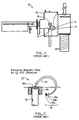
- FIG. 2 is a diagram of a prior art system adapted from page 39 of the book using a feed stock 24 contacting a water-cooled crucible 26.
- the feed stock As the material of the feed stock evaporates, the feed stock itself can be pushed upward to provide a continuous supply of the feed stock.
- the feed stock is not a subliming material, so a liquid inventory 24a is formed.
- the electron-beam source 28 includes a cathode block 28a, a filament 28b, and anodes 28c. Permanent magnets cause the 270° deflection of the electron-beam 30 so that the electron-beam 30 contacts the material of the rod 24.
- Subliming materials that do not produce a liquid inventory 24a.
- Subliming materials have the problem that, since no liquid inventory is formed, hot spots on the ingot surface can occur.
- the electron-beam may drill into the ingot material at the hot spot so that the erosion from the ingot surface is not even. This can require the ingot to be replaced when only a small percentage of the ingot was used.
- sweep mechanisms are used.
- One type of sweep mechanism is called X-Y sweep, because it varies the longitudinal and lateral positioning of the beam with a variable amplitude and frequency for each axis. This enables the electron-beam spot to be swept more uniformly over a wide range of source sizes.
- the X-Y sweep is used in conjunction with a continuous rod rotation and feed.
- a "Temescal" Model SRIHS-270-2 rod-fed electron gun uses such a rod feed and rotation mechanism, as well as an X-Y sweep mechanism.
- GB-A-1 151 818 discloses an apparatus providing an electron beam having a focus so adjusted that its diameter is equal to the radius of the body being vaporized and extending from the center of the end surface to the edge of the surface.
- the body is rotatable.
- a disadvantage of prior art rotational rod-fed systems is that it is difficult to maintain a uniform power density and thus evaporation rate from the rod tip.
- the invention generally contemplates using the ingot rod in a free-standing position so that the ingot rod does not contact the crucible near the tip of the rod. Preferably, the ingot rod does not contact the cooling crucible at all. It has been found that there are advantages of not contacting the crucible when the ingot rod material sublimes. Having the rod in the free-standing position generally allows the operation of the electron-beam evaporating system in a defocused position.
- an electron-beam An electron-beam evaporation system comprising an ingot rod, the ingot rod having a bottom end, a tip end and a side; an electron-beam evaporation source for evaporating the ingot rod; and a rotation mechanism connected to the bottom end of the ingot rod adapted to rotate the ingot rod while the electron-beam evaporation source acts on the tip of the ingot rod, wherein the ingot rod is free-standing so that the ingot rod does not contact a cooling crucible at the side of the ingot rod near the tip of the ingot rod.
- the electron-beam from the electron-beam source is roughly focused due to the 270° magnetic deflection.
- the prior art systems are set up so that the focal point of the electron-beam is near the tip of the rod. This allows for relatively high energy density.
- the ingot rod can be positioned so that the focal point of the electron-beam would be below the tip of the ingot rod.
- the ability to sweep the electron-beam energy over the edge of the tip of the rod is another advantage allowed by the free-standing position of the ingot rod. This happens and since the ingot rod is free-standing, the electron-beam does not contact the crucible.
- the defocused position of the ingot rod allowed in the invention helps to ensure that the electron-beam, when it sweeps over the edge, does not contact the crucible. This is because the electron-beam focuses to a point within the rod below the tip of the ingot rod. Thus, none of the electron-beam energy misses the rod and impinges on the crucible.
- the power density at the edges can be increased. This is an advantage because a radial sweep of the ingot tip can then be effected. Sweeping the electron-beam along the radius of the tip of the ingot rod has the advantage that it reduces the area of the sweep.
- a potential disadvantage of sweeping along the radius is that the power density near the edges can be relatively low. This may cause more material to be evaporated from the centre than the edges of the tip so that a ridge may be produced at the edge of the tip.
- Ingot rods are relatively expensive, for example, chromium rods currently cost about US$500.00. It is therefore important to get as much use of each ingot rod as possible.
- inventive concepts of the invention further include the operation of the device in the defocused position, the sweeping of the electron-beam energy over the edge of the tip of the ingot rod, and the sweeping of the electron-beam energy substantially along a radius of the ingot rod.
- Figure 1 is a diagram of a prior art electron-beam evaporation system in a vacuum process chamber as discussed above.
- Figure 2 is a diagram of a prior art electron-beam evaporation system again as discussed above.
- Figure 3 is a diagram of an electron-beam evaporation system of the invention illustrating two electron-beam scan positions.
- Figure 5 is a diagram illustrating the wear pattern of a prior art chromium ingot.
- Figure 6A is a diagram illustrating the wear of a chromium rod in the electron-beam evaporation system of the invention.
- Figure 6B is a diagram illustrating an unworn chromium rod for use with the electron-beam evaporation system of the invention.
- Figure 7 is a diagram illustrating some of the parts of the electron-beam evaporation system of the invention.
- Figure 8A is a cross-sectional view of a crucible for use with the electron-beam evaporation system of the invention.
- Figure 9 is a diagram illustrating some of the elements of the electron-beam evaporation system of the invention.
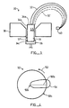
- Figure 3 is a diagram of an electron-beam evaporation system 30 of the invention illustrating an electron-beam 32 in two electron-beam sweep positions 32 and 32'.
- the system 30 shows a rod 34 having a tip portion 34a, a side portion 34b, and a bottom portion 34c.
- the bottom portion of the rod 34 is positioned in a rotating mechanism 36 and also connected to a feed mechanism (not shown).
- the rod material is a subliming material.
- this rod is made of chromium.
- Other subliming materials such as silicon dioxide, titanium dioxide, yttria-stabilised zirconia, HfO 2 , and Nd 2 O 3 can also be used with the invention.
- the rod 34 is free-standing, which means that the side of the rod near the tip does not contact the crucible 38. In a preferred embodiment, the entire rod does not contact the cooling crucible 38. It is against conventional wisdom for the rod to not contact the cooling crucible.
- the electron-beam source 40 is preferably of the type that provides a deflection of 270° caused by permanent magnets (not shown) and allows for an X-Y scan deflection caused by an electric current passing through a deflector coil (not shown).
- the electron-beam emitter is a "Temescal" high-performance emitter Type SFIH-270-2 available from BOC Coating Technology of Fairfield, California.
- the electron-beam 32 is shown in two positions 32 and 32'. In position 32', the electron-beam sweeps over the edge of the ingot tip to the ingot rod side. This allows for evaporation of material from the side of the rod. If the side of the rod near the tip were in contact with the crucible, the electron-beam would not be able to sweep the side of the ingot rod and would instead impinge upon the crucible.
- the sweep pattern 54 can be set so that only a part of the electron-beam will sweep the centre 50c of the tip 50. This can help reduce the amount that evaporates from the centre 50c as compared with the edge 50b.
- Preferred embodiments of the invention can produce a chromium evaporation rate of 30 Angstroms per second, 58 inches above the source, at 3 kilowatts of power. This is much better than the prior art deposition rate described below.
- the supplied power from the electron-beam is set at about two to three kilowatts.
- the tip of the rod is evenly eroded, almost the entire chromium rod can be used.
- Other subliming materials will also evaporate more evenly with the electron-beam evaporation system of the invention.
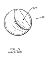
- FIG. 5 is a diagram illustrating the wear pattern of a chromium ingot used in a prior art electron-beam evaporation system.
- the ingot 60 is made of a chromium material.
- the chromium sublimes when heated by the electron-beam. Since the electron-beam evaporation is done in a high vacuum, the chromium does not reach the molten stage, and the erosion is very localised. To prevent the evaporation from being too localised, the electron-beam has to be swept at a high frequency, and with a large amplitude, to cover the entire chromium surface.
- Figure 6A is a diagram illustrating the wear of a chromium rod used with one embodiment of the invention.
- the rod 70 is substantially flat at the tip 70a but does have some small ridges at the tip. This flat shape remains after evaporating the chromium rod a distance d. Note that substantially all of the chromium rod 70 can be used. Also note that in location 70b, the evaporant system of the invention wears around the sides of the ingot rod 70 to help in providing the relatively uniform evaporation from the tip 70a.
- a motor 92 controls the vertical position of the unit 94, including the rod clamp 90. In this way, the rod can be fed up to the crucible (not shown) and positioned using motor 92 and rotated using motor 86. Rotational speed and the rod feeding is controlled by the power supplied to the motors 80 and 92 respectively.
- the crucible (not shown in Figure 7) is connected at position 96.
- the crucible itself is shown in Figures 8A and 8B below. Additional elements shown in Figure 9 are placed on the drive base top 98.
- the motor 80 is a "Globe Motor” Part No. M319M118 available from Globe Motor of Dayton, Ohio.
- the rod is rotated at around 30 revolutions per minute (RPM) during the evaporation process. Other rotational speeds can be used.
- FIG 8A is a cross-sectional drawing illustrating a crucible 100 for use with the invention.
- the crucible has an opening 100a through which the rod is fed. Note that, in a preferred embodiment, the crucible widens out into a V-shape at area 100b.
- the crucible 100 is water-cooled through pipes 102 and 104.
- the rod placed into the crucible does not contact the crucible, so that the diameter of the hole 100a is wider than the ingot rod.
- the ingot rod in a preferred embodiment, is about 1.25 inches in diameter.
- Figure 9 is a diagram illustrating additional elements of one embodiment of the electron-beam evaporation system of the invention.
- the elements shown in Figure 9 are placed on the drive base top 98 of Figure 7.
- the electron-beam gun 100 is preferably a "Temescal" high-performance emitter SFIH-270-2.
- the high-voltage filament lead 112 is connected to the emitter of the electron gun 110.
- a crucible 114 includes a through-hole 114a for a rod 116 to be fed therein.
- the electron-beam gun 110 has an associated deflection coil 118 that allows for the X and Y positioning of the electron-beam sweep onto the rod 116.
- the longitudinal sweep is driven by a signal having an amplitude of 0.5 to 0.7 amperes, with a sweep frequency of 4 Hertz, where the lateral sweep has a sweep frequency of 4 Hertz over an amplitude of -0.2 to +0.1 amperes.
- the electron-beam evaporation system of the invention can be used in conjunction with a monitoring device.
- a conventional monitoring device can be used where the monitor is positioned at about the same location as the substrate to give an indication of the amount of deposition material produced.
- a closed-loop control of the evaporation rate can be done by feeding back the detector signal to control a system parameter, preferably the power supply to the electron-beam gun, to maintain a constant deposition rate.
- the detector is a surface wave crystal detector whose frequency changes with the addition of deposited material.
- the pool-height monitor 120 includes a crystal holder 122, a shutter 124, a shutter actuator 126, and a collimating tube 128. These elements are mounted on a bracket 130.
- the detector points at a position about level with the crucible surface so that the detector determines when the rod is positioned slightly above the crucible surface.
- the system knows that the tip of the rod 116 is positioned slightly above the surface of the crucible 114. In this way, the rod 116 can be positioned before a substrate is coated. No windows that can become coated or flushing gases are required.
- the shutter 124 can close once the position of the rod 116 is determined. In this way, excessive coating of the crystal in the detector 122 can be prevented.
- Coolant and electrical lines 132 and the shielding 134 are also shown in Figure 9.
Landscapes
- Chemical & Material Sciences (AREA)
- Chemical Kinetics & Catalysis (AREA)
- Engineering & Computer Science (AREA)
- Materials Engineering (AREA)
- Mechanical Engineering (AREA)
- Metallurgy (AREA)
- Organic Chemistry (AREA)
- Health & Medical Sciences (AREA)
- Toxicology (AREA)
- Physical Vapour Deposition (AREA)
Description
- This invention relates to electron-beam evaporation systems, especially electron-beam evaporation systems for use with rod materials which sublimate when heated with an electron-beam at low pressures.
- Electron-beam evaporation systems direct an electron-beam to an ingot material to evaporate this material and coat a substrate. A discussion of electron-beam technology is given in the book "Physical Vapor Deposition", by R. Hill, 1986, Second Edition, at pages 17-106. Figure 1 is a diagram illustrating a prior art electron-beam evaporation system adapted from page 64 of the book. The system 10 includes an electron-
beam source 12 which supplies an electron-beam 14 to contact an ingot material positioned in acrucible 16. The evaporated ingot material is deposited on a substrate 18 in aprocess chamber 20. - Figure 2 is a diagram of a prior art system adapted from page 39 of the book using a
feed stock 24 contacting a water-cooledcrucible 26. As the material of the feed stock evaporates, the feed stock itself can be pushed upward to provide a continuous supply of the feed stock. In this diagram, the feed stock is not a subliming material, so aliquid inventory 24a is formed. The electron-beam source 28 includes acathode block 28a, afilament 28b, andanodes 28c. Permanent magnets cause the 270° deflection of the electron-beam 30 so that the electron-beam 30 contacts the material of therod 24. - It is also possible to use subliming materials that do not produce a
liquid inventory 24a. Subliming materials have the problem that, since no liquid inventory is formed, hot spots on the ingot surface can occur. The electron-beam may drill into the ingot material at the hot spot so that the erosion from the ingot surface is not even. This can require the ingot to be replaced when only a small percentage of the ingot was used. In order to avoid some of these problems, sweep mechanisms are used. One type of sweep mechanism is called X-Y sweep, because it varies the longitudinal and lateral positioning of the beam with a variable amplitude and frequency for each axis. This enables the electron-beam spot to be swept more uniformly over a wide range of source sizes. The X-Y sweep is used in conjunction with a continuous rod rotation and feed. A "Temescal" Model SRIHS-270-2 rod-fed electron gun uses such a rod feed and rotation mechanism, as well as an X-Y sweep mechanism. - GB-A-1 151 818 discloses an apparatus providing an electron beam having a focus so adjusted that its diameter is equal to the radius of the body being vaporized and extending from the center of the end surface to the edge of the surface. The body is rotatable.
- A disadvantage of prior art rotational rod-fed systems is that it is difficult to maintain a uniform power density and thus evaporation rate from the rod tip.
- The invention is concerned with an improved electron-beam evaporation system which can generally overcome such disadvantages.
- The essential features of the invention are defined in claim 1. Preferred embodiments are defined in claims 2 to 8.
- The invention generally contemplates using the ingot rod in a free-standing position so that the ingot rod does not contact the crucible near the tip of the rod. Preferably, the ingot rod does not contact the cooling crucible at all. It has been found that there are advantages of not contacting the crucible when the ingot rod material sublimes. Having the rod in the free-standing position generally allows the operation of the electron-beam evaporating system in a defocused position.
- In accordance with the invention, there is provided an electron-beam An electron-beam evaporation system comprising an ingot rod, the ingot rod having a bottom end, a tip end and a side; an electron-beam evaporation source for evaporating the ingot rod; and a rotation mechanism connected to the bottom end of the ingot rod adapted to rotate the ingot rod while the electron-beam evaporation source acts on the tip of the ingot rod, wherein the ingot rod is free-standing so that the ingot rod does not contact a cooling crucible at the side of the ingot rod near the tip of the ingot rod.
- The electron-beam from the electron-beam source is roughly focused due to the 270° magnetic deflection. Typically, the prior art systems are set up so that the focal point of the electron-beam is near the tip of the rod. This allows for relatively high energy density. When the ingot rod is in the free-standing position, the ingot rod can be positioned so that the focal point of the electron-beam would be below the tip of the ingot rod.
- In prior art systems, since the tip of the ingot rod is near the crucible, in order to sweep the edges of the ingot tip without hitting the crucible with the electron-beam, the electron-beam needs to be at least somewhat in focus. Since the tip is free-standing in the invention, a defocused beam can sweep somewhat over the edge of the ingot rod tip. The defocused position has the advantage of allowing a more even application of the electron-beam energy, and may help avoid hot spots.
- The ability to sweep the electron-beam energy over the edge of the tip of the rod is another advantage allowed by the free-standing position of the ingot rod. This happens and since the ingot rod is free-standing, the electron-beam does not contact the crucible.
- The defocused position of the ingot rod allowed in the invention helps to ensure that the electron-beam, when it sweeps over the edge, does not contact the crucible. This is because the electron-beam focuses to a point within the rod below the tip of the ingot rod. Thus, none of the electron-beam energy misses the rod and impinges on the crucible.
- Since the electron-beam energy can be swept over the edge of the ingot rod, the power density at the edges can be increased. This is an advantage because a radial sweep of the ingot tip can then be effected. Sweeping the electron-beam along the radius of the tip of the ingot rod has the advantage that it reduces the area of the sweep. A potential disadvantage of sweeping along the radius is that the power density near the edges can be relatively low. This may cause more material to be evaporated from the centre than the edges of the tip so that a ridge may be produced at the edge of the tip.
- By sweeping over the edge of the rod tip, additional material from the edge portion can be evaporated, thus producing a relatively flat evaporation pattern.
- It is important to have a relatively flat evaporation pattern because this allows for a good utilisation of the ingot rod. If the electron-beam bores down in one location, the electron-beam can contact the pusher material, and the ingot rod will need to be replaced. Ingot rods are relatively expensive, for example, chromium rods currently cost about US$500.00. It is therefore important to get as much use of each ingot rod as possible.
- The inventive concepts of the invention further include the operation of the device in the defocused position, the sweeping of the electron-beam energy over the edge of the tip of the ingot rod, and the sweeping of the electron-beam energy substantially along a radius of the ingot rod.
- For a better understanding of the invention, reference will now be made, by way of exemplification only, to the accompanying drawings, in which:
- Figure 1 is a diagram of a prior art electron-beam evaporation system in a vacuum process chamber as discussed above.
- Figure 2 is a diagram of a prior art electron-beam evaporation system again as discussed above.
- Figure 3 is a diagram of an electron-beam evaporation system of the invention illustrating two electron-beam scan positions.
- Figure 4 is a diagram of the tip of the ingot rod illustrating the ingot rod rotation and showing an illustrative sweep pattern.
- Figure 5 is a diagram illustrating the wear pattern of a prior art chromium ingot.
- Figure 6A is a diagram illustrating the wear of a chromium rod in the electron-beam evaporation system of the invention.
- Figure 6B is a diagram illustrating an unworn chromium rod for use with the electron-beam evaporation system of the invention.
- Figure 7 is a diagram illustrating some of the parts of the electron-beam evaporation system of the invention.
- Figure 8A is a cross-sectional view of a crucible for use with the electron-beam evaporation system of the invention.
- Figure 8B is a top view of the crucible of Figure 8A.
- Figure 9 is a diagram illustrating some of the elements of the electron-beam evaporation system of the invention.
- With reference to the drawings, Figure 3 is a diagram of an electron-
beam evaporation system 30 of the invention illustrating an electron-beam 32 in two electron-beam sweep positions 32 and 32'. Thesystem 30 shows arod 34 having atip portion 34a, aside portion 34b, and a bottom portion 34c. The bottom portion of therod 34 is positioned in arotating mechanism 36 and also connected to a feed mechanism (not shown). In a preferred embodiment, the rod material is a subliming material. In a preferred embodiment, this rod is made of chromium. Other subliming materials such as silicon dioxide, titanium dioxide, yttria-stabilised zirconia, HfO2, and Nd2O3 can also be used with the invention. - As shown, the
rod 34 is free-standing, which means that the side of the rod near the tip does not contact thecrucible 38. In a preferred embodiment, the entire rod does not contact the coolingcrucible 38. It is against conventional wisdom for the rod to not contact the cooling crucible. - As described below, the free-standing rod produces a number of advantages. The electron-
beam source 40 is preferably of the type that provides a deflection of 270° caused by permanent magnets (not shown) and allows for an X-Y scan deflection caused by an electric current passing through a deflector coil (not shown). In the preferred embodiment, the electron-beam emitter is a "Temescal" high-performance emitter Type SFIH-270-2 available from BOC Coating Technology of Fairfield, California. - The electron-
beam 32 is shown in twopositions 32 and 32'. In position 32', the electron-beam sweeps over the edge of the ingot tip to the ingot rod side. This allows for evaporation of material from the side of the rod. If the side of the rod near the tip were in contact with the crucible, the electron-beam would not be able to sweep the side of the ingot rod and would instead impinge upon the crucible. - The free-standing
ingot rod 34 allows for the system to be used in a defocused position which helps ensure that the electron-beam can sweep the side of the rod but without impinging on the crucible. Additionally, the defocused position allows for a more uniform sweep of the ingot rod. In a preferred embodiment, the tip of theingot rod 34 is positioned above the focal point of the electron-beam 32. The tip of theingot rod 34 is preferably about 1.5 inches higher than was used before. As shown in Figure 3, electron-beam 32 would have a focal point at point A whereas electron-beam 32' would have a focal point at point B. - The importance of sweeping the sides of the ingot rod with the electron-beam can be best seen with respect to Figure 4 illustrating an
ingot rod tip 50. Theingot rod tip 50 is rotated as shown byarrow 52. - In a preferred embodiment, the electron-beam sweeps substantially about the
radius 50a of thetip 50. A sweep about a radius of the tip is easier to control than a full sweep of the entire tip of the ingot rod. A smaller area needs be swept, so that the power density can be maintained relatively uniform. However, if the supplied electron-beam power were completely uniform along thelinear radius 50a, the power density at theedge 50b of thetip 50 would be less than the power density at thecentre 50c of thetip 50. This would result in a ridge forming around theedge 50b because the material of theedge 50b would not evaporate as quickly as the material at thecentre 50c. By sweeping over the edge, as shown insweep pattern 54, the material at theedge 50b is evaporated more quickly, and a more even evaporation pattern is produced at thetip 50. - Operating in the defocused position can help reduce the power density at the centre and thus produce a more even erosion pattern. The
sweep pattern 54 can be set so that only a part of the electron-beam will sweep thecentre 50c of thetip 50. This can help reduce the amount that evaporates from thecentre 50c as compared with theedge 50b. - Preferred embodiments of the invention can produce a chromium evaporation rate of 30 Angstroms per second, 58 inches above the source, at 3 kilowatts of power. This is much better than the prior art deposition rate described below. In preferred embodiments, the supplied power from the electron-beam is set at about two to three kilowatts. In the invention, since the tip of the rod is evenly eroded, almost the entire chromium rod can be used. Other subliming materials will also evaporate more evenly with the electron-beam evaporation system of the invention.
- Figure 5 is a diagram illustrating the wear pattern of a chromium ingot used in a prior art electron-beam evaporation system. The
ingot 60 is made of a chromium material. As discussed above, the chromium sublimes when heated by the electron-beam. Since the electron-beam evaporation is done in a high vacuum, the chromium does not reach the molten stage, and the erosion is very localised. To prevent the evaporation from being too localised, the electron-beam has to be swept at a high frequency, and with a large amplitude, to cover the entire chromium surface. The chromium evaporation rate, from a 67 cc crucible source, has been found to be three to four Angstroms per second, 42 inches above the source, at 5.5 kilowatts. Since the electron-beam has to be swept over almost four square inches in the case of a 67 cc ingot, the power density of the electron-beam inevitably varies over such a large area and the evaporation rate differs from spot to spot. Eventually, the evaporation will be more severe at a certain spot and the electron-beam will tunnel into the chromium. Plasma focusing will make the evaporation more and more localised. This is illustrated byarea 60a of theingot 60. The evaporation rate diminishes because a smaller area is being evaporated, and soon the chromium rod has to be replaced. For the non-rod-fed ingot source used with the Figure 5, only about fifteen percent of the initial volume will be consumed before the rest of the ingot rod needs to be discarded. - Figure 6A is a diagram illustrating the wear of a chromium rod used with one embodiment of the invention. Note that the
rod 70 is substantially flat at the tip 70a but does have some small ridges at the tip. This flat shape remains after evaporating the chromium rod a distance d. Note that substantially all of thechromium rod 70 can be used. Also note that inlocation 70b, the evaporant system of the invention wears around the sides of theingot rod 70 to help in providing the relatively uniform evaporation from the tip 70a. - Figure 6B illustrates an
unworn chromium rod 72 for use with the electron-beam evaporation system of the invention. Note that, in a preferred embodiment, thechromium rod 72 is about 1.25 inches in diameter. - Figure 7 illustrates some of the parts used in a preferred embodiment of the electron-beam evaporation system of the invention; the crucible and the electron-beam source are not shown in this figure. A
motor 80 connected to amotor mount 82 drives gears 84 to cause rotation in thehexagonal drive rod 86. This rotation is translated from thehexagonal sleeve 88 to theclamps 90 and thus the ingot rod. Themotor 80 controls the speed of the rotation of the rod (not shown) clamped into aclamp 90. The rotation is translated to thehexagonal drive rod 86 whatever the vertical position of thehexagonal sleeve 88, because thehexagonal sleeve 88 slideably fits into thehexagonal drive shaft 86. Amotor 92 controls the vertical position of theunit 94, including therod clamp 90. In this way, the rod can be fed up to the crucible (not shown) and positioned usingmotor 92 and rotated usingmotor 86. Rotational speed and the rod feeding is controlled by the power supplied to themotors position 96. The crucible itself is shown in Figures 8A and 8B below. Additional elements shown in Figure 9 are placed on thedrive base top 98. - In a preferred embodiment, the
motor 80 is a "Globe Motor" Part No. M319M118 available from Globe Motor of Dayton, Ohio. In a preferred embodiment, the rod is rotated at around 30 revolutions per minute (RPM) during the evaporation process. Other rotational speeds can be used. - Figure 8A is a cross-sectional drawing illustrating a
crucible 100 for use with the invention. The crucible has an opening 100a through which the rod is fed. Note that, in a preferred embodiment, the crucible widens out into a V-shape atarea 100b. As shown in Figure 8B, thecrucible 100 is water-cooled throughpipes - Figure 9 is a diagram illustrating additional elements of one embodiment of the electron-beam evaporation system of the invention. The elements shown in Figure 9 are placed on the
drive base top 98 of Figure 7. The electron-beam gun 100 is preferably a "Temescal" high-performance emitter SFIH-270-2. The high-voltage filament lead 112 is connected to the emitter of theelectron gun 110. Acrucible 114 includes a through-hole 114a for arod 116 to be fed therein. The electron-beam gun 110 has an associateddeflection coil 118 that allows for the X and Y positioning of the electron-beam sweep onto therod 116. In a preferred embodiment, the longitudinal sweep is driven by a signal having an amplitude of 0.5 to 0.7 amperes, with a sweep frequency of 4 Hertz, where the lateral sweep has a sweep frequency of 4 Hertz over an amplitude of -0.2 to +0.1 amperes. - The electron-beam evaporation system of the invention can be used in conjunction with a monitoring device. A conventional monitoring device can be used where the monitor is positioned at about the same location as the substrate to give an indication of the amount of deposition material produced. In this way, a closed-loop control of the evaporation rate can be done by feeding back the detector signal to control a system parameter, preferably the power supply to the electron-beam gun, to maintain a constant deposition rate. In one embodiment, the detector is a surface wave crystal detector whose frequency changes with the addition of deposited material.
- Additionally, as shown in Figure 9, an inventive pool-height monitor can be used in conjunction with the invention. The pool-height monitor is described in our co-pending patent application of even date and same title (inventors P.A. Joel Smith and Ping Chang), the contents of which are incorporated herein by reference. Briefly, as shown in Figure 9, the pool-
height monitor 120 includes acrystal holder 122, ashutter 124, ashutter actuator 126, and acollimating tube 128. These elements are mounted on abracket 130. The detector points at a position about level with the crucible surface so that the detector determines when the rod is positioned slightly above the crucible surface. When this occurs, some of the evaporated material will move in a straight line throughcollimating tube 128 to thedetector 122. Once a signal is detected, the system knows that the tip of therod 116 is positioned slightly above the surface of thecrucible 114. In this way, therod 116 can be positioned before a substrate is coated. No windows that can become coated or flushing gases are required. Theshutter 124 can close once the position of therod 116 is determined. In this way, excessive coating of the crystal in thedetector 122 can be prevented. - Also shown in Figure 9 is the coolant and
electrical lines 132 and the shielding 134.
Claims (8)
- An electron-beam evaporation system comprising:characterised in that the electron-beam evaporation source (40) is adapted to sweep an electron-beam substantially along a radius (50a) of the tip (50,34a) of ingot rod, the sweep going beyond an edge (50b) of the tip to evaporate material from the side (34b) of the ingot rod.an ingot rod (34), the ingot rod (34,50) having a bottom end (34c), a tip end (34a,50), and a side (34b);an electron-beam evaporation source (40) for evaporating the ingot rod (34);a rotation mechanism (36) connected to the bottom end (34c)of the ingot rod (34) adapted to rotate the ingot rod (34) while the electron-beam evaporation source (40) acts on the tip (34a,50) of the ingot rod(34), wherein the ingot rod (34) is free-standing so that the ingot rod (34) does not contact a cooling crucible (38,100) at the side (34b) of the ingot rod (34) near the tip (34) of the ingot rod;
- An electron-beam evaporation system according to Claim 1 in which the electron-beam evaporation source (40) defines a focal point for the electron-beam and wherein the tip (34a,50) of the ingot rod is positioned above the focal point.
- An electron-beam evaporation system according to Claim 1 or Claim 2 in which the ingot rod (34) comprises a material that sublimes when heated by an electron-beam in a low-pressure environment.
- An electron-beam evaporation system according to any preceding claim in which the ingot rod (34) includes a cylindrical portion defining a central longitudinal axis and wherein the rotating means (36) rotates the ingot rod about the central longitudinal axis.
- An electron-beam evaporation system according to any preceding claim in which the electron-beam evaporation source (40) comprises an electron-beam gun (40,110) to produce an electron-beam and a magnet to deflect the electron-beam through an arc of about 270 degrees.
- An electron-beam evaporation system according to any preceding claim in which the electron-beam evaporation source (40) further comprises magnetic coils (118) that can deflect the electron-beam to form a sweeping pattern on the ingot rod.
- An electron-beam evaporation system according to any preceding claim in which the rotation mechanism (36) comprises a motor (92).
- An electron-beam evaporation system according to any preceding claim further comprising a rod feeding mechanism (80-88).
Applications Claiming Priority (2)
| Application Number | Priority Date | Filing Date | Title |
|---|---|---|---|
| US08/880,246 US5905753A (en) | 1997-06-23 | 1997-06-23 | Free-standing rotational rod-fed source |
| US880246 | 1997-06-23 |
Publications (2)
| Publication Number | Publication Date |
|---|---|
| EP0887435A1 EP0887435A1 (en) | 1998-12-30 |
| EP0887435B1 true EP0887435B1 (en) | 2003-01-15 |
Family
ID=25375834
Family Applications (1)
| Application Number | Title | Priority Date | Filing Date |
|---|---|---|---|
| EP98304861A Expired - Lifetime EP0887435B1 (en) | 1997-06-23 | 1998-06-19 | Free-standing rotating evaporation source |
Country Status (6)
| Country | Link |
|---|---|
| US (1) | US5905753A (en) |
| EP (1) | EP0887435B1 (en) |
| JP (1) | JP4397979B2 (en) |
| KR (1) | KR100495647B1 (en) |
| CA (1) | CA2237280C (en) |
| DE (1) | DE69810704T2 (en) |
Cited By (1)
| Publication number | Priority date | Publication date | Assignee | Title |
|---|---|---|---|---|
| DE102009037326A1 (en) | 2009-08-14 | 2011-02-17 | Von Ardenne Anlagentechnik Gmbh | Method for the vacuum deposition of substrates comprises forming an active electrode surface of an electrode of an electrode arrangement in the process chamber whilst the electrode surface is added and removed |
Families Citing this family (5)
| Publication number | Priority date | Publication date | Assignee | Title |
|---|---|---|---|---|
| DE102007008674B4 (en) * | 2006-02-20 | 2010-03-25 | Von Ardenne Anlagentechnik Gmbh | Method and device for long-term stable coating of flat substrates |
| US8748773B2 (en) * | 2007-03-30 | 2014-06-10 | Ati Properties, Inc. | Ion plasma electron emitters for a melting furnace |
| DE102009005513B4 (en) | 2009-01-20 | 2015-12-10 | Von Ardenne Gmbh | Method and device for long-term stable coating of substrates by electron beam evaporation |
| DE102010041150A1 (en) * | 2010-05-26 | 2011-12-01 | Von Ardenne Anlagentechnik Gmbh | Vacuum coating the substrates, comprises impinging an evaporation source on surface part of evaporation product in vacuum by energy source directed on the surface parts of the evaporation product at a point of impingement location |
| EP3725911A1 (en) * | 2019-04-16 | 2020-10-21 | Max-Planck-Gesellschaft zur Förderung der Wissenschaften e.V. | Source arrangement, deposition apparatus and method for depositing source material |
Family Cites Families (13)
| Publication number | Priority date | Publication date | Assignee | Title |
|---|---|---|---|---|
| GB1037675A (en) * | 1962-05-08 | 1966-08-03 | Lucas Industries Ltd | Vacuum deposition of metals |
| DE1521251B2 (en) * | 1966-05-03 | 1970-03-26 | Farbenfabriken Bayer Aktiengesellschaft, 5090 Leverkusen | Device and method for uniform evaporation and application of refractory materials, in particular quartz |
| US3377419A (en) * | 1966-06-29 | 1968-04-09 | Lokomotivbau Elektrotech | Electron beam multichamber high vacuum furnace |
| US3454814A (en) * | 1966-07-29 | 1969-07-08 | Atomic Energy Commission | Tubular vapor source |
| US3730962A (en) * | 1971-08-24 | 1973-05-01 | Airco Inc | Electron beam furance with material-evaporant equilibrium control |
| US3756193A (en) * | 1972-05-01 | 1973-09-04 | Battelle Memorial Institute | Coating apparatus |
| US4130416A (en) * | 1973-04-19 | 1978-12-19 | Zaboronok Georgy F | Method of preparing a furnace charge when smelting refractory metals and alloys |
| US4027093A (en) * | 1976-03-01 | 1977-05-31 | Optical Coating Laboratory, Inc. | Ingot gripper assembly |
| DE2650215A1 (en) * | 1976-11-02 | 1978-05-11 | G F Paul Dipl Phys Dr Mueller | Vacuum vapour deposition appts. - in which material being evaporated can be rotated and moved axially for uniform evapn. by electron beam |
| DE3420246A1 (en) * | 1984-05-30 | 1985-12-05 | Leybold-Heraeus GmbH, 5000 Köln | EVAPORATOR FOR VACUUM VACUUM DEVICES |
| EP0381912B1 (en) * | 1989-02-09 | 1994-03-09 | Balzers Aktiengesellschaft | Method to centre an electron beam |
| DE4305721C1 (en) * | 1993-02-25 | 1994-07-21 | Dresden Vakuumtech Gmbh | Low-voltage arc evaporator with refill device and method for its use |
| JPH07220273A (en) * | 1994-01-26 | 1995-08-18 | Sony Corp | Method of manufacturing magnetic recording medium |
-
1997
- 1997-06-23 US US08/880,246 patent/US5905753A/en not_active Expired - Lifetime
-
1998
- 1998-05-11 CA CA002237280A patent/CA2237280C/en not_active Expired - Lifetime
- 1998-06-19 EP EP98304861A patent/EP0887435B1/en not_active Expired - Lifetime
- 1998-06-19 DE DE69810704T patent/DE69810704T2/en not_active Expired - Lifetime
- 1998-06-23 KR KR10-1998-0023665A patent/KR100495647B1/en not_active Expired - Fee Related
- 1998-06-23 JP JP17630798A patent/JP4397979B2/en not_active Expired - Lifetime
Cited By (1)
| Publication number | Priority date | Publication date | Assignee | Title |
|---|---|---|---|---|
| DE102009037326A1 (en) | 2009-08-14 | 2011-02-17 | Von Ardenne Anlagentechnik Gmbh | Method for the vacuum deposition of substrates comprises forming an active electrode surface of an electrode of an electrode arrangement in the process chamber whilst the electrode surface is added and removed |
Also Published As
| Publication number | Publication date |
|---|---|
| EP0887435A1 (en) | 1998-12-30 |
| US5905753A (en) | 1999-05-18 |
| KR100495647B1 (en) | 2005-09-30 |
| JPH1161390A (en) | 1999-03-05 |
| JP4397979B2 (en) | 2010-01-13 |
| CA2237280A1 (en) | 1998-12-23 |
| KR19990007237A (en) | 1999-01-25 |
| CA2237280C (en) | 2007-01-02 |
| DE69810704D1 (en) | 2003-02-20 |
| DE69810704T2 (en) | 2003-10-16 |
Similar Documents
| Publication | Publication Date | Title |
|---|---|---|
| US4673477A (en) | Controlled vacuum arc material deposition, method and apparatus | |
| JP2571948B2 (en) | Arc coating of refractory metal compounds | |
| EP2788522B1 (en) | Filtered cathodic arc deposition apparatus and method | |
| US5084300A (en) | Apparatus for the ablation of material from a target and coating method and apparatus | |
| US4310614A (en) | Method and apparatus for pretreating and depositing thin films on substrates | |
| US4951604A (en) | System and method for vacuum deposition of thin films | |
| JP4066044B2 (en) | Film forming method and sputtering apparatus | |
| JPS63213662A (en) | Apparatus and method for vacuum vapor deposition of membrane | |
| JPH11140630A (en) | Cathode arc vapor deposition device | |
| US3329524A (en) | Centrifugal-type vapor source | |
| CA1130476A (en) | Pretreatment of substrates prior to thin film deposition | |
| EP1356496B1 (en) | Apparatus for evaporation of materials for coating objects | |
| US5905753A (en) | Free-standing rotational rod-fed source | |
| US5238546A (en) | Method and apparatus for vaporizing materials by plasma arc discharge | |
| EP0174977A4 (en) | REGULATED DEPOSITION OF MATERIAL BY VACUUM ARC, METHOD AND APPARATUS. | |
| JPH0219459A (en) | Evaporation source assembly having cruucible | |
| JP3338467B2 (en) | Method and apparatus for guiding and centering an electron beam | |
| EP0444538B1 (en) | Device and procedure for vacuum evaporation of a material and utilisation of the procedure | |
| US3883679A (en) | Vapor source assembly | |
| CN215440663U (en) | Combined film plating machine for thermal evaporation and deposition of plating material on vertical workpiece from side vertical surface | |
| JP2859344B2 (en) | Electron beam position adjusting method and electron beam position adjusting device | |
| DE4006456C1 (en) | Appts. for vaporising material in vacuum - has electron beam gun or laser guided by electromagnet to form cloud or pre-melted spot on the target surface | |
| JPH02182876A (en) | ion plating equipment | |
| JP3554030B2 (en) | Small thermoelectron vacuum arc evaporation source | |
| JPH02125868A (en) | Electron-beam vapor deposition device |
Legal Events
| Date | Code | Title | Description |
|---|---|---|---|
| PUAI | Public reference made under article 153(3) epc to a published international application that has entered the european phase |
Free format text: ORIGINAL CODE: 0009012 |
|
| AK | Designated contracting states |
Kind code of ref document: A1 Designated state(s): BE CH DE FR GB IT LI LU NL |
|
| AX | Request for extension of the european patent |
Free format text: AL;LT;LV;MK;RO;SI |
|
| 17P | Request for examination filed |
Effective date: 19990607 |
|
| AKX | Designation fees paid |
Free format text: BE CH DE FR GB IT LI LU NL |
|
| 17Q | First examination report despatched |
Effective date: 20010314 |
|
| GRAH | Despatch of communication of intention to grant a patent |
Free format text: ORIGINAL CODE: EPIDOS IGRA |
|
| GRAH | Despatch of communication of intention to grant a patent |
Free format text: ORIGINAL CODE: EPIDOS IGRA |
|
| GRAA | (expected) grant |
Free format text: ORIGINAL CODE: 0009210 |
|
| AK | Designated contracting states |
Kind code of ref document: B1 Designated state(s): BE CH DE FR GB IT LI LU NL |
|
| REG | Reference to a national code |
Ref country code: GB Ref legal event code: FG4D Ref country code: CH Ref legal event code: EP |
|
| REF | Corresponds to: |
Ref document number: 69810704 Country of ref document: DE Date of ref document: 20030220 Kind code of ref document: P |
|
| REG | Reference to a national code |
Ref country code: CH Ref legal event code: NV Representative=s name: RIEDERER HASLER & PARTNER PATENTANWAELTE AG |
|
| PG25 | Lapsed in a contracting state [announced via postgrant information from national office to epo] |
Ref country code: LU Free format text: LAPSE BECAUSE OF NON-PAYMENT OF DUE FEES Effective date: 20030619 |
|
| ET | Fr: translation filed | ||
| PLBE | No opposition filed within time limit |
Free format text: ORIGINAL CODE: 0009261 |
|
| STAA | Information on the status of an ep patent application or granted ep patent |
Free format text: STATUS: NO OPPOSITION FILED WITHIN TIME LIMIT |
|
| 26N | No opposition filed |
Effective date: 20031016 |
|
| REG | Reference to a national code |
Ref country code: CH Ref legal event code: PUE Owner name: EDWARDS VACUUM, INC. Free format text: THE BOC GROUP, INC.#575 MOUNTAIN AVENUE#MURRAY HILL, NEW PROVIDENCE, NEW JERSEY 07974-2082 (US) -TRANSFER TO- EDWARDS VACUUM, INC.#301 BALLARDVALE STREET#WILMINGTON, MA 01844 (US) Ref country code: CH Ref legal event code: NV Representative=s name: RIEDERER HASLER & PARTNER PATENTANWAELTE AG |
|
| BECA | Be: change of holder's address |
Owner name: EDWARDS VACUUM INC.301 BALLARDVALE STREET, WILMING Effective date: 20071212 |
|
| BECN | Be: change of holder's name |
Owner name: EDWARDS VACUUM INC. Effective date: 20071212 |
|
| REG | Reference to a national code |
Ref country code: GB Ref legal event code: 732E |
|
| NLS | Nl: assignments of ep-patents |
Owner name: BOC EDWARDS, INC. Effective date: 20071122 |
|
| NLT1 | Nl: modifications of names registered in virtue of documents presented to the patent office pursuant to art. 16 a, paragraph 1 |
Owner name: EDWARDS VACUUM, INC. |
|
| REG | Reference to a national code |
Ref country code: FR Ref legal event code: TP Ref country code: FR Ref legal event code: CD |
|
| REG | Reference to a national code |
Ref country code: FR Ref legal event code: CA |
|
| REG | Reference to a national code |
Ref country code: CH Ref legal event code: PUE Owner name: FERROTEC (USA) CORPORATION Free format text: EDWARDS VACUUM, INC.#301 BALLARDVALE STREET#WILMINGTON, MA 01844 (US) -TRANSFER TO- FERROTEC (USA) CORPORATION#33 CONSTITUTION DRIVE#BEDFORD, NH 03110 (US) |
|
| REG | Reference to a national code |
Ref country code: GB Ref legal event code: 732E Free format text: REGISTERED BETWEEN 20100722 AND 20100728 |
|
| REG | Reference to a national code |
Ref country code: FR Ref legal event code: TP Ref country code: FR Ref legal event code: CA |
|
| REG | Reference to a national code |
Ref country code: CH Ref legal event code: NV Representative=s name: RIEDERER HASLER & PARTNER PATENTANWAELTE AG |
|
| REG | Reference to a national code |
Ref country code: NL Ref legal event code: SD Effective date: 20101202 |
|
| BECA | Be: change of holder's address |
Owner name: FERROTEC USA CORP.33 CONSTITUTION DRIVE, BEDFORD, Effective date: 20101206 |
|
| PGFP | Annual fee paid to national office [announced via postgrant information from national office to epo] |
Ref country code: GB Payment date: 20130626 Year of fee payment: 16 Ref country code: CH Payment date: 20130521 Year of fee payment: 16 Ref country code: DE Payment date: 20130627 Year of fee payment: 16 |
|
| PGFP | Annual fee paid to national office [announced via postgrant information from national office to epo] |
Ref country code: IT Payment date: 20130624 Year of fee payment: 16 Ref country code: NL Payment date: 20130620 Year of fee payment: 16 |
|
| PGFP | Annual fee paid to national office [announced via postgrant information from national office to epo] |
Ref country code: BE Payment date: 20130619 Year of fee payment: 16 |
|
| PGFP | Annual fee paid to national office [announced via postgrant information from national office to epo] |
Ref country code: FR Payment date: 20130716 Year of fee payment: 16 |
|
| REG | Reference to a national code |
Ref country code: DE Ref legal event code: R119 Ref document number: 69810704 Country of ref document: DE |
|
| REG | Reference to a national code |
Ref country code: NL Ref legal event code: V1 Effective date: 20150101 |
|
| REG | Reference to a national code |
Ref country code: CH Ref legal event code: PL |
|
| GBPC | Gb: european patent ceased through non-payment of renewal fee |
Effective date: 20140619 |
|
| REG | Reference to a national code |
Ref country code: FR Ref legal event code: ST Effective date: 20150227 |
|
| PG25 | Lapsed in a contracting state [announced via postgrant information from national office to epo] |
Ref country code: NL Free format text: LAPSE BECAUSE OF NON-PAYMENT OF DUE FEES Effective date: 20150101 |
|
| REG | Reference to a national code |
Ref country code: DE Ref legal event code: R119 Ref document number: 69810704 Country of ref document: DE Effective date: 20150101 |
|
| PG25 | Lapsed in a contracting state [announced via postgrant information from national office to epo] |
Ref country code: LI Free format text: LAPSE BECAUSE OF NON-PAYMENT OF DUE FEES Effective date: 20140630 Ref country code: DE Free format text: LAPSE BECAUSE OF NON-PAYMENT OF DUE FEES Effective date: 20150101 Ref country code: CH Free format text: LAPSE BECAUSE OF NON-PAYMENT OF DUE FEES Effective date: 20140630 Ref country code: IT Free format text: LAPSE BECAUSE OF NON-PAYMENT OF DUE FEES Effective date: 20140619 |
|
| PG25 | Lapsed in a contracting state [announced via postgrant information from national office to epo] |
Ref country code: GB Free format text: LAPSE BECAUSE OF NON-PAYMENT OF DUE FEES Effective date: 20140619 Ref country code: FR Free format text: LAPSE BECAUSE OF NON-PAYMENT OF DUE FEES Effective date: 20140630 |
|
| PG25 | Lapsed in a contracting state [announced via postgrant information from national office to epo] |
Ref country code: BE Free format text: LAPSE BECAUSE OF NON-PAYMENT OF DUE FEES Effective date: 20140630 |