EP0886726B1 - Method and system for distributing vapors or gases to each cylinder of a multicylinder engine - Google Patents
Method and system for distributing vapors or gases to each cylinder of a multicylinder engine Download PDFInfo
- Publication number
- EP0886726B1 EP0886726B1 EP97903178A EP97903178A EP0886726B1 EP 0886726 B1 EP0886726 B1 EP 0886726B1 EP 97903178 A EP97903178 A EP 97903178A EP 97903178 A EP97903178 A EP 97903178A EP 0886726 B1 EP0886726 B1 EP 0886726B1
- Authority
- EP
- European Patent Office
- Prior art keywords
- flow
- network
- engine
- intake manifold
- grooves
- Prior art date
- Legal status (The legal status is an assumption and is not a legal conclusion. Google has not performed a legal analysis and makes no representation as to the accuracy of the status listed.)
- Expired - Lifetime
Links
Images

Classifications
-
- F—MECHANICAL ENGINEERING; LIGHTING; HEATING; WEAPONS; BLASTING
- F02—COMBUSTION ENGINES; HOT-GAS OR COMBUSTION-PRODUCT ENGINE PLANTS
- F02M—SUPPLYING COMBUSTION ENGINES IN GENERAL WITH COMBUSTIBLE MIXTURES OR CONSTITUENTS THEREOF
- F02M35/00—Combustion-air cleaners, air intakes, intake silencers, or induction systems specially adapted for, or arranged on, internal-combustion engines
- F02M35/10—Air intakes; Induction systems
- F02M35/104—Intake manifolds
- F02M35/112—Intake manifolds for engines with cylinders all in one line
-
- F—MECHANICAL ENGINEERING; LIGHTING; HEATING; WEAPONS; BLASTING
- F02—COMBUSTION ENGINES; HOT-GAS OR COMBUSTION-PRODUCT ENGINE PLANTS
- F02M—SUPPLYING COMBUSTION ENGINES IN GENERAL WITH COMBUSTIBLE MIXTURES OR CONSTITUENTS THEREOF
- F02M35/00—Combustion-air cleaners, air intakes, intake silencers, or induction systems specially adapted for, or arranged on, internal-combustion engines
- F02M35/10—Air intakes; Induction systems
-
- F—MECHANICAL ENGINEERING; LIGHTING; HEATING; WEAPONS; BLASTING
- F02—COMBUSTION ENGINES; HOT-GAS OR COMBUSTION-PRODUCT ENGINE PLANTS
- F02M—SUPPLYING COMBUSTION ENGINES IN GENERAL WITH COMBUSTIBLE MIXTURES OR CONSTITUENTS THEREOF
- F02M35/00—Combustion-air cleaners, air intakes, intake silencers, or induction systems specially adapted for, or arranged on, internal-combustion engines
- F02M35/10—Air intakes; Induction systems
- F02M35/10006—Air intakes; Induction systems characterised by the position of elements of the air intake system in direction of the air intake flow, i.e. between ambient air inlet and supply to the combustion chamber
- F02M35/10078—Connections of intake systems to the engine
-
- F—MECHANICAL ENGINEERING; LIGHTING; HEATING; WEAPONS; BLASTING
- F02—COMBUSTION ENGINES; HOT-GAS OR COMBUSTION-PRODUCT ENGINE PLANTS
- F02M—SUPPLYING COMBUSTION ENGINES IN GENERAL WITH COMBUSTIBLE MIXTURES OR CONSTITUENTS THEREOF
- F02M35/00—Combustion-air cleaners, air intakes, intake silencers, or induction systems specially adapted for, or arranged on, internal-combustion engines
- F02M35/10—Air intakes; Induction systems
- F02M35/10209—Fluid connections to the air intake system; their arrangement of pipes, valves or the like
- F02M35/10222—Exhaust gas recirculation [EGR]; Positive crankcase ventilation [PCV]; Additional air admission, lubricant or fuel vapour admission
-
- F—MECHANICAL ENGINEERING; LIGHTING; HEATING; WEAPONS; BLASTING
- F02—COMBUSTION ENGINES; HOT-GAS OR COMBUSTION-PRODUCT ENGINE PLANTS
- F02M—SUPPLYING COMBUSTION ENGINES IN GENERAL WITH COMBUSTIBLE MIXTURES OR CONSTITUENTS THEREOF
- F02M35/00—Combustion-air cleaners, air intakes, intake silencers, or induction systems specially adapted for, or arranged on, internal-combustion engines
- F02M35/10—Air intakes; Induction systems
- F02M35/104—Intake manifolds
- F02M35/1045—Intake manifolds characterised by the charge distribution between the cylinders/combustion chambers or its homogenisation
-
- F—MECHANICAL ENGINEERING; LIGHTING; HEATING; WEAPONS; BLASTING
- F02—COMBUSTION ENGINES; HOT-GAS OR COMBUSTION-PRODUCT ENGINE PLANTS
- F02M—SUPPLYING COMBUSTION ENGINES IN GENERAL WITH COMBUSTIBLE MIXTURES OR CONSTITUENTS THEREOF
- F02M35/00—Combustion-air cleaners, air intakes, intake silencers, or induction systems specially adapted for, or arranged on, internal-combustion engines
- F02M35/10—Air intakes; Induction systems
- F02M35/10314—Materials for intake systems
- F02M35/10321—Plastics; Composites; Rubbers
-
- F—MECHANICAL ENGINEERING; LIGHTING; HEATING; WEAPONS; BLASTING
- F02—COMBUSTION ENGINES; HOT-GAS OR COMBUSTION-PRODUCT ENGINE PLANTS
- F02M—SUPPLYING COMBUSTION ENGINES IN GENERAL WITH COMBUSTIBLE MIXTURES OR CONSTITUENTS THEREOF
- F02M35/00—Combustion-air cleaners, air intakes, intake silencers, or induction systems specially adapted for, or arranged on, internal-combustion engines
- F02M35/10—Air intakes; Induction systems
- F02M35/1034—Manufacturing and assembling intake systems
- F02M35/10347—Moulding, casting or the like
-
- F—MECHANICAL ENGINEERING; LIGHTING; HEATING; WEAPONS; BLASTING
- F05—INDEXING SCHEMES RELATING TO ENGINES OR PUMPS IN VARIOUS SUBCLASSES OF CLASSES F01-F04
- F05C—INDEXING SCHEME RELATING TO MATERIALS, MATERIAL PROPERTIES OR MATERIAL CHARACTERISTICS FOR MACHINES, ENGINES OR PUMPS OTHER THAN NON-POSITIVE-DISPLACEMENT MACHINES OR ENGINES
- F05C2225/00—Synthetic polymers, e.g. plastics; Rubber
- F05C2225/08—Thermoplastics
Definitions
- Modern automotive engines are often designed so that various vapors and/or gases generated as a byproduct of engine operation are drawn back into the air flow in the intake manifold, so that the byproduct vapors and/or gases are mixed into the intake air flow to be burned in the engine. This is done in order to reduce polluting emissions otherwise occurring during operation of the automobile.
- crankcase vapors are caused to flow through an external hose and PCV valve into the intake manifold at a point just below the throttle plate, where the vapors are mixed with air flow drawn into the engine cylinders.
- Fuel vapor emissions from the fuel tank during fueling and also during engine operation are currently contained by use of a fuel vapor adsorbing canister, which is connected to the fuel tank to receive displaced fuel vapors.
- the adsorbed fuel vapor in the canister is periodically purged from the canister by being drawn into the intake manifold via an external hose and purge control solenoid.
- Exhaust gas recirculation is another measure used to reduce the emission of oxides of nitrogen, a portion of the exhaust gas is recirculated back into the intake manifold in order to be mixed into the combustible mixture for induction into the engine cylinders.
- Air assist fuel injection is a recent innovation which directs an auxiliary air flow to the fuel injectors which is directed into the fuel spray from each injector to improve the atomization of the injected fuel.
- the auxiliary air is currently supplied via an external air rail which receives air flow from an air pump, or which is induced by a vacuum from the intake manifold.
- the prior art distribution method for recirculating byproduct fluids such as crankcase vapors, canister purge fuel vapor, and exhaust gas does not produce an exact uniformity of the air-fluid mixture drawn into each individual cylinder of a multicylinder engine. This is because these fluids are introduced into the intake manifold upstream of the manifold runners, and disproportionate flow of the added fluid in the individual runners may occur due to a variety of local flow conditions in each runner.
- Sophisticated engine controls rely on an O 2 sensor detecting the oxygen content of the exhaust to produce a constant optimal air-to-fuel ratio by varying the volume of fuel injected by the fuel injectors as the O 2 sensor signals indicate a shift in the air-to-fuel ratio.
- This control thereby minimizes engine emissions by operating as closely as possible to the desired air-to-fuel ratio at all times.
- the O 2 sensor detects the average level of oxygen in the exhaust gases. Increasingly stringent emission standards make it desirable that an exact air-to-fuel ratio be maintained as much as possible.
- An object of the present invention is to provide an auxiliary flow distribution system providing improved cylinder-to-cylinder distribution of the volume of the byproduct fluids drawn into the cylinders of a multicylinder engine.
- EP-A-0576 729 describes an intake manifold which includes at least one intake pipe with an intake flange for attachment to the cylinder head; and a bypass line for feeding a secondary gas into the intake opening.
- an intake manifold for an internal combustion engine comprises a plenum chamber for receiving a flow of air; a plurality of runners extending from said plenum chamber, each runner having an end terminating in a runner port communicating with an associated runner passage aligned with a respective one of a series of intake ports in an engine cylinder head, with said intake manifold mounted to said cylinder head; a mounting flange integral with said runner ports having a mounting face adapted to be abutted against said cylinder head with said intake manifold mounted thereto: an auxiliary fluid distribution system comprised of a secondary fluid inlet opening in said flange and a network of flow grooves recessed into said flange mounting face extending from said inlet opening to each runner port, whereby a fluid introduced into said flange inlet opening is distributed to each cylinder head intake port via said flow grooves, wherein said flow grooves in said network are configured to produce substantially equal flow resistance to fluid flowing in said flow grooves, where
- a method of introducing a by-product fluid generated as a by-product of operation of a multicylinder engine into said engine for burning in combustion chambers defined by the cylinders of said engine comprises the steps of: directing a flow of said by-product fluid through a network of individual flow passages, each leading to a location adjacent a respective engine cylinder, and comprising grooves recessed into a mounting face of a manifold mounting flange, and balancing flow in each passage so that an equal volume of by-product fluid flow is directed to each cylinder, characterised in that said method further includes the step of directing a flow of assist air flow to each of a series of fuel injectors via a further network of flow passages recessed into said flange mounting face separate from said other networks.
- the intake manifold itself is preferably of a molded composite plastic construction, in which case the grooves are molded into the flange face at the time the manifold is formed.
- Each of the networks are supplied with a respective inlet opening for receiving the gas or vapor flows.
- These may include one or more fluids generated as a by-product of engine operation, such as recirculated exhaust gas, crankcase vapors, and evaporative purge vapors from an adsorption canister.
- the grooves in the respective networks may be sealed from each other by means of seals disposed in grooves in the manifold flange face extending alongside either side of the respective flow passage grooves.
- the various grooves leading to particular engine cylinders are variously sized in cross sectional area increasingly proportionate to their relative length to produce balanced flow to each cylinder.
- the resultant flow distribution pattern insures uniform volumes of each gas or vapor to each engine cylinder and eliminates the cost and complexity of much of the plumbing which otherwise would be required.
- crankcase vapors and evaporative canister purge vapors are advantageously combined into a single flow network since they are compatible and have a complementary effect in keeping the grooves clear of lubricating oil sludge, since the fuel vapors tend to flush out the heavier oil deposits in the grooves.
- the present invention provides a distribution system comprised of one or more auxiliary flow passage networks integrated into the mounting flange of an intake manifold 12. These networks are provided for distributing one or more of fluids generated as a byproduct of engine operation, such as crankcase vapors, fuel vapor contained in the absorption canister, or exhaust gas. A network can also be provided for distributing air assist flow to the fuel injectors as described in further detail below.
- the intake manifold 12 is preferably of a molded composite plastic, having a series of individual runners 14 exiting from a plenum 16.
- the plenum 16 receives an air flow induced to flow into a throttle body 18 (Figure 3B) mounted to flange 20 having an opening 22 entering into the interior of the plenum 16.
- a duct 19 connects to a remotely located air cleaner 17.
- Each runner 14 has an internal passage which terminates in an individual manifold port 24 recessed into a manifold mounting flange 10, each manifold port 24 aligned with a respective one of a series of cylinder intake ports 26 formed along the cylinder head 28, each cylinder head port 26 in turn aligned with an engine cylinder 30 (Figure 3B).
- a fuel injector pocket 25 is adjacent each port 24, allowing a fuel injector (not shown) to spray a fuel charge into the air flow at timed intervals. It is noted that the fuel injector pockets could also be formed in the cylinder head in alternative designs.
- the intake manifold mounting flange 10 has a mounting face 32 defined by a series of raised ribs adapted to be abutted against a cylinder head mounting surface 34.
- a series of mounting holes 36 with metal inserts receive studs (not shown), to allow the manifold to be mounted to the cylinder head surface 34.
- the manifold plenum 16, runners 14, and ports 24 define the primary air distribution system for supplying a combustible mixture to the engine cylinders in conventional fashion.
- the intake manifold is provided with one or more auxiliary distribution systems, which in the embodiment shown in Figure 2, consists of a network of flow passages 40A, 40B, 40C, 40D, each passage terminating in a respective manifold intake port 24.
- the flow passages 40A-40D are comprised of grooves recessed into the mounting face 32 of the manifold mounting flange 10.
- the flow passages 40A-40D originate in an inlet opening 42 formed in flange 10 into which is introduced a byproduct vapor such as crankcase or purge vapors. In that instance, both vapors may be introduced into the same flow passage network, since there is a beneficial effect from both vapors flowing through the same distribution network.
- An external plumbing connection 44 from a multicylinder internal combustion engine 45 to an adsorption canister 46 directs a flow of purge vapors to the outside of inlet opening 42 in the flange 10.
- a cored passage 48 in the engine block 50 extends from the interior of the oil pan 52 to a second cored passage 54 in the cylinder head 28, which has a terminus aligned with the inlet opening of the network flow passages 40A-40D.
- the flow passages 40A-40D are sealed on each side by an elongated elastomeric seal 58 received in a seal groove 60 which also encircles each intake port 24 to also act as a main sealing gasket for the manifold flange 10.
- the flow passages 40A-40D are configured so as to present equal flow resistance, i.e., the cross sectional areas are increasingly proportional to their relative lengths, so as to balance fluid flow to each intake port 24.
- PCV and evaporative purge vapors are distributed to the engine cylinders
- other byproduct fluids such as exhaust gas, can be distributed in the same manner, either alternatively or in addition to the vapors.
- the air assist flow can be distributed to the injectors in this manner.
- FIG. 4 diagrammatically shows such a system in which an intake manifold 50 has a plurality of runners 62A-62D leading to a corresponding series of cylinder port openings 64A-64D on the mounting flange 66.
- a series of injector seats 68A-68D are also provided as before.
- a first network 70 directs flow of fuel and crankcase vapors from a port 72 to each cylinder port opening 64A-64D.
- a second network 74 directs flow of exhaust gas from a port to each cylinder port 64A-64D, the exhaust gas received from a duct 78 from the exhaust gas recirculation valve 80.
- a third network 82 directs a flow of assist air to each injector port 68A-68D, the air distributed from a port 86.
- Each network 70, 74, 82 comprises a set of grooves in the flanges 68 sealed from each other. Small sections of passages 88 extending below the flange face will be necessary to avoid cross flows where the grooves of networks 70-74 cross.
Landscapes
- Engineering & Computer Science (AREA)
- Chemical & Material Sciences (AREA)
- Combustion & Propulsion (AREA)
- Mechanical Engineering (AREA)
- General Engineering & Computer Science (AREA)
- Supplying Secondary Fuel Or The Like To Fuel, Air Or Fuel-Air Mixtures (AREA)
- Lubrication Details And Ventilation Of Internal Combustion Engines (AREA)
Abstract
Description
- Modern automotive engines are often designed so that various vapors and/or gases generated as a byproduct of engine operation are drawn back into the air flow in the intake manifold, so that the byproduct vapors and/or gases are mixed into the intake air flow to be burned in the engine. This is done in order to reduce polluting emissions otherwise occurring during operation of the automobile.
- For example, crankcase vapors are caused to flow through an external hose and PCV valve into the intake manifold at a point just below the throttle plate, where the vapors are mixed with air flow drawn into the engine cylinders.
- Fuel vapor emissions from the fuel tank during fueling and also during engine operation are currently contained by use of a fuel vapor adsorbing canister, which is connected to the fuel tank to receive displaced fuel vapors. The adsorbed fuel vapor in the canister is periodically purged from the canister by being drawn into the intake manifold via an external hose and purge control solenoid.
- Exhaust gas recirculation is another measure used to reduce the emission of oxides of nitrogen, a portion of the exhaust gas is recirculated back into the intake manifold in order to be mixed into the combustible mixture for induction into the engine cylinders.
- Air assist fuel injection is a recent innovation which directs an auxiliary air flow to the fuel injectors which is directed into the fuel spray from each injector to improve the atomization of the injected fuel.
- The auxiliary air is currently supplied via an external air rail which receives air flow from an air pump, or which is induced by a vacuum from the intake manifold.
- The prior art distribution method for recirculating byproduct fluids such as crankcase vapors, canister purge fuel vapor, and exhaust gas does not produce an exact uniformity of the air-fluid mixture drawn into each individual cylinder of a multicylinder engine. This is because these fluids are introduced into the intake manifold upstream of the manifold runners, and disproportionate flow of the added fluid in the individual runners may occur due to a variety of local flow conditions in each runner.
- While design efforts are made to insure that these fluids are thoroughly mixed into the manifold air flow, some cylinder-to-cylinder variations in the mixture as received into the various cylinders inevitably occurs as noted.
- Sophisticated engine controls rely on an O2 sensor detecting the oxygen content of the exhaust to produce a constant optimal air-to-fuel ratio by varying the volume of fuel injected by the fuel injectors as the O2 sensor signals indicate a shift in the air-to-fuel ratio. This control thereby minimizes engine emissions by operating as closely as possible to the desired air-to-fuel ratio at all times. The O2 sensor detects the average level of oxygen in the exhaust gases. Increasingly stringent emission standards make it desirable that an exact air-to-fuel ratio be maintained as much as possible. The uneven volume of the byproduct vapors and gases introduced into each cylinder results in the actual air-to-fuel ratio varying considerably due to the effect of cylinder-to-cylinder distribution of crankcase vapors, purge vapors, and exhaust gases so that higher emission levels will likely result.
- An additional disadvantage of prior art air assist systems is that extensive external plumbing is required for directing the air assist flow to the injectors adding to the cost and complexity of the engine.
- An object of the present invention is to provide an auxiliary flow distribution system providing improved cylinder-to-cylinder distribution of the volume of the byproduct fluids drawn into the cylinders of a multicylinder engine.
- It is another object to provide such an auxiliary flow distribution system which is also capable of directing air assist flow to each fuel injector with minimal cost and complexity.
- It is still another object to provide such a low cost, simplified fluid distribution system in combination with an engine intake manifold.
- EP-A-0576 729 describes an intake manifold which includes at least one intake pipe with an intake flange for attachment to the cylinder head; and a bypass line for feeding a secondary gas into the intake opening.
- In accordance with a first aspect of the present invention an intake manifold for an internal combustion engine comprises a plenum chamber for receiving a flow of air; a plurality of runners extending from said plenum chamber, each runner having an end terminating in a runner port communicating with an associated runner passage aligned with a respective one of a series of intake ports in an engine cylinder head, with said intake manifold mounted to said cylinder head; a mounting flange integral with said runner ports having a mounting face adapted to be abutted against said cylinder head with said intake manifold mounted thereto: an auxiliary fluid distribution system comprised of a secondary fluid inlet opening in said flange and a network of flow grooves recessed into said flange mounting face extending from said inlet opening to each runner port, whereby a fluid introduced into said flange inlet opening is distributed to each cylinder head intake port via said flow grooves, wherein said flow grooves in said network are configured to produce substantially equal flow resistance to fluid flowing in said flow grooves, whereby a balance flow of fluid introduced to each intake port is produced, characterised in that said intake manifold further comprises: a further port in said flange, a plurality of injector ports, a further network of flow grooves each extending to a respective fuel injector and recessed into said flange mounting face, whereby air distributed from said further port via said further network of flow grooves to said injector ports provides an auxiliary air assist flow to fuel injectors with minimal cost and complexity.
- In accordance with a second aspect of the present invention a method of introducing a by-product fluid generated as a by-product of operation of a multicylinder engine into said engine for burning in combustion chambers defined by the cylinders of said engine, comprises the steps of: directing a flow of said by-product fluid through a network of individual flow passages, each leading to a location adjacent a respective engine cylinder, and comprising grooves recessed into a mounting face of a manifold mounting flange, and balancing flow in each passage so that an equal volume of by-product fluid flow is directed to each cylinder, characterised in that said method further includes the step of directing a flow of assist air flow to each of a series of fuel injectors via a further network of flow passages recessed into said flange mounting face separate from said other networks.
- The intake manifold itself is preferably of a molded composite plastic construction, in which case the grooves are molded into the flange face at the time the manifold is formed.
- Each of the networks are supplied with a respective inlet opening for receiving the gas or vapor flows. These may include one or more fluids generated as a by-product of engine operation, such as recirculated exhaust gas, crankcase vapors, and evaporative purge vapors from an adsorption canister.
- The grooves in the respective networks may be sealed from each other by means of seals disposed in grooves in the manifold flange face extending alongside either side of the respective flow passage grooves. The various grooves leading to particular engine cylinders are variously sized in cross sectional area increasingly proportionate to their relative length to produce balanced flow to each cylinder.
- The resultant flow distribution pattern insures uniform volumes of each gas or vapor to each engine cylinder and eliminates the cost and complexity of much of the plumbing which otherwise would be required.
- In the preferred form of the distribution system, the crankcase vapors and evaporative canister purge vapors are advantageously combined into a single flow network since they are compatible and have a complementary effect in keeping the grooves clear of lubricating oil sludge, since the fuel vapors tend to flush out the heavier oil deposits in the grooves.
-
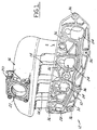
- Figure 1 is a perspective view of an intake manifold having an auxiliary flow passage network according to the invention.
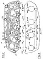
- Figure 2 is a front view of the mounting flange of the intake manifold shown in Figure 1, showing the details of the auxiliary flow passage network.
- Figures 3A and 3B are diagrammatic end and side elevational views of an engine having an intake manifold providing an auxiliary flow passage network for receiving crankcase and canister vapors and directing a flow of both vapors to each individual cylinder.
- Figure 4 is a diagrammatic representation of an intake manifold flange having a multiple flange passage network version of the present invention.
-
- In the following detailed description, certain specific terminology will be employed for the sake of clarity and a particular embodiment described in accordance with the requirements of 35 USC 112, but it is to be understood that the same is not intended to be limiting and should not be so construed inasmuch as the invention is capable of taking many forms and variations within the scope of the appended claims.
- Referring to the drawings, the present invention provides a distribution system comprised of one or more auxiliary flow passage networks integrated into the mounting flange of an
intake manifold 12. These networks are provided for distributing one or more of fluids generated as a byproduct of engine operation, such as crankcase vapors, fuel vapor contained in the absorption canister, or exhaust gas. A network can also be provided for distributing air assist flow to the fuel injectors as described in further detail below. - The
intake manifold 12 is preferably of a molded composite plastic, having a series ofindividual runners 14 exiting from aplenum 16. Theplenum 16 receives an air flow induced to flow into a throttle body 18 (Figure 3B) mounted toflange 20 having an opening 22 entering into the interior of theplenum 16. Aduct 19 connects to a remotely locatedair cleaner 17. - Each
runner 14 has an internal passage which terminates in anindividual manifold port 24 recessed into amanifold mounting flange 10, eachmanifold port 24 aligned with a respective one of a series ofcylinder intake ports 26 formed along thecylinder head 28, eachcylinder head port 26 in turn aligned with an engine cylinder 30 (Figure 3B). - A
fuel injector pocket 25 is adjacent eachport 24, allowing a fuel injector (not shown) to spray a fuel charge into the air flow at timed intervals. It is noted that the fuel injector pockets could also be formed in the cylinder head in alternative designs. - The intake
manifold mounting flange 10 has a mountingface 32 defined by a series of raised ribs adapted to be abutted against a cylinderhead mounting surface 34. A series ofmounting holes 36 with metal inserts receive studs (not shown), to allow the manifold to be mounted to thecylinder head surface 34. - The
manifold plenum 16,runners 14, andports 24 define the primary air distribution system for supplying a combustible mixture to the engine cylinders in conventional fashion. - According to the concept of the present invention, the intake manifold is provided with one or more auxiliary distribution systems, which in the embodiment shown in Figure 2, consists of a network of
flow passages manifold intake port 24. Theflow passages 40A-40D are comprised of grooves recessed into the mountingface 32 of themanifold mounting flange 10. - The
flow passages 40A-40D originate in aninlet opening 42 formed inflange 10 into which is introduced a byproduct vapor such as crankcase or purge vapors. In that instance, both vapors may be introduced into the same flow passage network, since there is a beneficial effect from both vapors flowing through the same distribution network. - This is indicated diagrammatically in Figures 3A and 3B. An
external plumbing connection 44 from a multicylinderinternal combustion engine 45 to anadsorption canister 46 directs a flow of purge vapors to the outside ofinlet opening 42 in theflange 10. Acored passage 48 in theengine block 50 extends from the interior of theoil pan 52 to a second coredpassage 54 in thecylinder head 28, which has a terminus aligned with the inlet opening of thenetwork flow passages 40A-40D. - The
flow passages 40A-40D are sealed on each side by an elongatedelastomeric seal 58 received in aseal groove 60 which also encircles eachintake port 24 to also act as a main sealing gasket for themanifold flange 10. - The
flow passages 40A-40D are configured so as to present equal flow resistance, i.e., the cross sectional areas are increasingly proportional to their relative lengths, so as to balance fluid flow to eachintake port 24. - While in the example described above PCV and evaporative purge vapors are distributed to the engine cylinders, other byproduct fluids, such as exhaust gas, can be distributed in the same manner, either alternatively or in addition to the vapors.
- Also, the air assist flow can be distributed to the injectors in this manner.
- Figure 4 diagrammatically shows such a system in which an
intake manifold 50 has a plurality of runners 62A-62D leading to a corresponding series of cylinder port openings 64A-64D on themounting flange 66. A series ofinjector seats 68A-68D are also provided as before. - According to this aspect of the invention, a series of flow passage networks are provided.
- A
first network 70 directs flow of fuel and crankcase vapors from aport 72 to each cylinder port opening 64A-64D. - A
second network 74 directs flow of exhaust gas from a port to each cylinder port 64A-64D, the exhaust gas received from aduct 78 from the exhaustgas recirculation valve 80. - A
third network 82 directs a flow of assist air to eachinjector port 68A-68D, the air distributed from aport 86. - Each
network passages 88 extending below the flange face will be necessary to avoid cross flows where the grooves of networks 70-74 cross. - Thus, an assured uniform distribution of each of the fluids and vapors is provided by a relative low cost structure.
Claims (13)
- An intake manifold (12) for an internal combustion engine comprising:characterised in that said intake manifold further comprises:a plenum chamber (16) for receiving a flow of air;a plurality of runners (14) extending from said plenum chamber (16), each runner (14) having an end terminating in a runner port (24) communicating with an associated runner passage aligned with a respective one of a series of intake ports (26) in an engine cylinder head (28), with said intake manifold mounted to said cylinder head;a mounting flange (10) integral with said runner ports having a mounting face (32) adapted to be abutted against said cylinder head (28) with said intake manifold (12) mounted thereto:an auxiliary fluid distribution system comprised of a secondary fluid inlet opening (42) in said flange and a network of flow grooves (40A-40D) recessed into said flange mounting face (32) extending from said inlet opening to each runner port, whereby a fluid introduced into said flange inlet opening is distributed to each cylinder head intake port via said flow grooves, wherein said flow grooves in said network are configured to produce substantially equal flow resistance to fluid flowing in said flow grooves, whereby a balance flow of fluid introduced to each intake port is produced,a further port (86) in said flange,a plurality of injector ports (68A-68D),a further network of flow grooves (82) each extending to a respective fuel injector and recessed into said flange mounting face, whereby air distributed from said further port (86) via said further network of flow grooves (82) to said injector ports provides an auxiliary air assist flow to fuel injectors with minimal cost and complexity.
- The intake manifold according to Claim 1, further including a seal groove (60) extending on each side of each of said flow grooves (40A-40D) and or said further flow grooves (68A-68D) and sealing means (58) received into each of said seal grooves.
- The intake manifold according to Claim 1, further including a second inlet opening (78) and a second network of grooves (74) recessed into said flange mounting face (32) extending from said second inlet opening to each runner port (24), whereby a second fluid can be distributed to each cylinder head intake port.
- The intake manifold according to Claim 3, further including sealing means isolating said first, second and further network of sealing grooves.
- An intake manifold for an internal combustion engine as claimed in any preceding claim, whereby said auxiliary fluid distribution system operates to direct by-product fluid generated as a by-product of operation of said engine into cylinders of said engine.
- An intake manifold for an internal combustion engine according to Claim 5, wherein said engine has a crankcase and said by-product fluid comprises crankcase vapours drawn into said first network of flow passages (70).
- An intake manifold for an internal combustion engine according to Claim 6, further including a fuel vapour adsorption canister (46) and wherein said canister is purged of said fuel vapour to generate a by-product fluid, said fuel vapours also directed into said first network of flow passages (70).
- An intake manifold for an internal combustion engine according to Claim 5 wherein another by-product fluid is directed into said second network of flow passages (74).
- An intake manifold for an internal combustion engine according to Claim 8, wherein said another by-product fluid comprises exhaust gas directed into said second network of flow passages (74).
- A method of introducing a by-product fluid generated as a by-product of operation of a multicylinder engine (45) into said engine for burning in combustion chambers defined by the cylinders of said engine, comprising the steps of:characterised in that said method further includes the step of directing a flow of assist air flow to each of a series of fuel injectors via a further network of flow passages (82) recessed into said flange mounting face separate from said other networks (70, 74).directing a flow of said by-product fluid through a network of individual flow passages (70), each leading to a location adjacent a respective engine cylinder, and comprising grooves recessed into a mounting face (32) of a manifold mounting flange (10), andbalancing flow in each passage so that an equal volume of by-product fluid flow is directed to each cylinder,
- The method according to Claim 10, wherein said engine produces crankcase vapours, said method including the step of providing separate flow passages (70), each leading directly to one of said engine cylinders, and directing said crankcase vapours into each engine cylinder via said separate flow passages.
- The method according to Claim 11, wherein said engine also includes an adsorption canister (46) for collecting fuel vapours, and wherein said fuel vapours and said crankcase vapours are sent through a common network of flow passages including an individual flow passage leading to each respective engine cylinder.
- The method according to Claim 10, further including the step of directing recirculated exhaust gas back into said engine cylinders via a separate network of flow passages (74).
Applications Claiming Priority (3)
| Application Number | Priority Date | Filing Date | Title |
|---|---|---|---|
| US613565 | 1996-03-11 | ||
| US08/613,565 US5813375A (en) | 1996-03-11 | 1996-03-11 | Method and system for distributing vapors or gases to each cylinder of a multicylinder engine |
| PCT/CA1997/000131 WO1997034081A1 (en) | 1996-03-11 | 1997-02-26 | Method and system for distributing vapors or gases to each cylinder of a multicylinder engine |
Publications (2)
| Publication Number | Publication Date |
|---|---|
| EP0886726A1 EP0886726A1 (en) | 1998-12-30 |
| EP0886726B1 true EP0886726B1 (en) | 2002-05-15 |
Family
ID=24457801
Family Applications (1)
| Application Number | Title | Priority Date | Filing Date |
|---|---|---|---|
| EP97903178A Expired - Lifetime EP0886726B1 (en) | 1996-03-11 | 1997-02-26 | Method and system for distributing vapors or gases to each cylinder of a multicylinder engine |
Country Status (6)
| Country | Link |
|---|---|
| US (1) | US5813375A (en) |
| EP (1) | EP0886726B1 (en) |
| KR (1) | KR19990087675A (en) |
| BR (1) | BR9708178A (en) |
| DE (1) | DE69712611T2 (en) |
| WO (1) | WO1997034081A1 (en) |
Cited By (1)
| Publication number | Priority date | Publication date | Assignee | Title |
|---|---|---|---|---|
| DE10318664B4 (en) * | 2002-06-12 | 2007-11-29 | Hyundai Motor Company | Distribution system for passing gas of an engine |
Families Citing this family (18)
| Publication number | Priority date | Publication date | Assignee | Title |
|---|---|---|---|---|
| DE19757986A1 (en) * | 1997-12-24 | 1999-07-01 | Mann & Hummel Filter | Intake device for an internal combustion engine |
| JP3051391B1 (en) * | 1999-01-27 | 2000-06-12 | 愛知機械工業株式会社 | Intake manifold |
| DE10004552A1 (en) | 2000-02-02 | 2001-08-09 | Mann & Hummel Filter | Intake pipe with integrated exhaust gas recirculation |
| SE520863C2 (en) * | 2000-05-05 | 2003-09-09 | Volvo Personvagnar Ab | Method and apparatus for venting gases in an internal combustion engine |
| DE10036128A1 (en) * | 2000-07-25 | 2002-02-07 | Volkswagen Ag | Internal combustion engine and method for active ventilation of the cylinder crankcase thereof |
| DE20014711U1 (en) * | 2000-08-25 | 2000-11-23 | Filterwerk Mann + Hummel GmbH, 71638 Ludwigsburg | Device for recirculating gas on an internal combustion engine |
| DE10105555B4 (en) * | 2001-02-06 | 2016-02-25 | Volkswagen Ag | Ventilation device for oil-laden gases of an internal combustion engine |
| DE50209572D1 (en) | 2001-07-20 | 2007-04-12 | Mann & Hummel Gmbh | Fastening device for an intake manifold |
| DE102005051434A1 (en) * | 2005-10-27 | 2007-05-03 | Bayerische Motoren Werke Ag | Internal combustion engine has inlet port for gases from crank case ventilation and exhaust gas recirculation valve are kept at moderate temperature by coolant cycle |
| JP2009167962A (en) * | 2008-01-18 | 2009-07-30 | Toyota Motor Corp | Evaporative fuel processing device for internal combustion engine |
| DE102010002233A1 (en) | 2010-02-23 | 2011-08-25 | Behr GmbH & Co. KG, 70469 | Device for exhaust gas recirculation for an internal combustion engine |
| FR2958336B1 (en) | 2010-03-31 | 2013-03-15 | Valeo Systemes Thermiques | MANIFOLD FOR GAS DISTRIBUTION IN THE CYLINDER HEAD OF AN ENGINE WITH RECIRCULATED EXHAUST GAS MIXTURE WITH COUNTER-CURRENT ADMISSION GASES. |
| FR2958337B1 (en) * | 2010-03-31 | 2013-03-01 | Valeo Systemes Thermiques | MANIFOLD FOR GAS DISTRIBUTION IN THE CYLINDER HEAD OF AN ENGINE, ASSEMBLY OF A DISTRIBUTION MANIFOLD AND A CYLINDER HEAD. |
| FR2961559B1 (en) * | 2010-06-18 | 2014-05-09 | Peugeot Citroen Automobiles Sa | ADMISSION FLANGE FOR AN ADMISSION SPLITTER |
| CN101975120A (en) * | 2010-11-22 | 2011-02-16 | 北京理工大学 | Intake manifold gasket device for engine |
| CN101979856A (en) * | 2010-11-22 | 2011-02-23 | 北京理工大学 | Cylinder cover device with communicated air inlet channels for engine |
| DE102011111124A1 (en) * | 2011-08-20 | 2013-02-21 | GM Global Technology Operations LLC (n. d. Gesetzen des Staates Delaware) | Fastening device for fastening intake manifold to cylinder head of internal combustion engine, has clamping wedge attached to flange side and displaced by clamping device such that manifold front side is pressed on inlet front side |
| USD1085161S1 (en) * | 2025-02-24 | 2025-07-22 | Xiaodan Chen | Intake manifold |
Family Cites Families (12)
| Publication number | Priority date | Publication date | Assignee | Title |
|---|---|---|---|---|
| JPH0350283Y2 (en) * | 1985-04-09 | 1991-10-28 | ||
| GB2203487A (en) * | 1987-04-03 | 1988-10-19 | Ford Motor Co | A fuel injection system component |
| JPH02107758U (en) * | 1989-02-14 | 1990-08-28 | ||
| US5005535A (en) * | 1989-02-27 | 1991-04-09 | Outboard Marine Corporation | Internal Combustion engine with recessed intake manifold |
| US4922866A (en) * | 1989-05-25 | 1990-05-08 | Brunswick Corporation | Fuel injector assembly |
| US5063887A (en) * | 1989-08-14 | 1991-11-12 | Yamaha Hatsudoki Kabushiki Kaisha | Exhaust control valve system for parallel multi-cylinder two-cycle engine |
| US5003933A (en) * | 1989-11-06 | 1991-04-02 | General Motors Corporation | Integrated induction system |
| FR2655382B1 (en) * | 1989-12-04 | 1992-04-17 | Peugeot | DEVICE FOR INTRODUCING ADDITIONAL GAS, SUCH AS AIR, INTO AN INTERNAL COMBUSTION ENGINE AND ENGINE EQUIPPED WITH SUCH A DEVICE. |
| US5022355A (en) * | 1990-04-23 | 1991-06-11 | Outboard Motor Corporation | Internal combustion engine |
| JPH0610776A (en) * | 1992-06-26 | 1994-01-18 | Honda Motor Co Ltd | Exhaust gas recirculation device and manufacturing method thereof |
| DE4221913C1 (en) * | 1992-07-03 | 1994-01-27 | Freudenberg Carl Fa | Intake manifold for an internal combustion engine with a cylinder head |
| US5603295A (en) * | 1992-08-22 | 1997-02-18 | Ing. H.C.F. Porsche Ag | Internal-combustion engine comprising an intake system |
-
1996
- 1996-03-11 US US08/613,565 patent/US5813375A/en not_active Expired - Fee Related
-
1997
- 1997-02-26 BR BR9708178A patent/BR9708178A/en not_active IP Right Cessation
- 1997-02-26 EP EP97903178A patent/EP0886726B1/en not_active Expired - Lifetime
- 1997-02-26 DE DE69712611T patent/DE69712611T2/en not_active Expired - Fee Related
- 1997-02-26 WO PCT/CA1997/000131 patent/WO1997034081A1/en not_active Ceased
- 1997-02-26 KR KR1019980707139A patent/KR19990087675A/en not_active Ceased
Cited By (1)
| Publication number | Priority date | Publication date | Assignee | Title |
|---|---|---|---|---|
| DE10318664B4 (en) * | 2002-06-12 | 2007-11-29 | Hyundai Motor Company | Distribution system for passing gas of an engine |
Also Published As
| Publication number | Publication date |
|---|---|
| DE69712611D1 (en) | 2002-06-20 |
| WO1997034081A1 (en) | 1997-09-18 |
| US5813375A (en) | 1998-09-29 |
| DE69712611T2 (en) | 2002-11-28 |
| KR19990087675A (en) | 1999-12-27 |
| BR9708178A (en) | 1999-07-27 |
| EP0886726A1 (en) | 1998-12-30 |
Similar Documents
| Publication | Publication Date | Title |
|---|---|---|
| US5813375A (en) | Method and system for distributing vapors or gases to each cylinder of a multicylinder engine | |
| EP0736684B1 (en) | Internal combustion engine intake manifold | |
| EP3043061A1 (en) | Intake system for internal combustion engine | |
| US5201301A (en) | Adjustable ambient air filtering system and pollution control device | |
| GB2386158A (en) | Intake system for internal combustion engine | |
| US3446196A (en) | Fuel gasifier system | |
| US4483292A (en) | Internal combustion engine | |
| US6155223A (en) | Distribution reservoir for an internal combustion engine | |
| US20020069861A1 (en) | EGR system | |
| US6343593B1 (en) | Fuel composition optimizer and carbon dioxide emissions reducer based on an air-vacuum liquid compensation system | |
| AU585884B2 (en) | Fuel-economy and emission-control device for internal combustion engines | |
| US12429021B2 (en) | Fuel injection throttle body assembly having a fuel distribution sleeve | |
| WO2000051751A2 (en) | Induction system cleaning method and apparatus | |
| US4430982A (en) | Carburetor for an internal combustion engine | |
| CA1208088A (en) | Internal combustion engine | |
| KR19990015081A (en) | Vehicle exhaust and blow-by gas recirculation system for preventing carbon deposition in throttle body | |
| US20070114680A1 (en) | Carburettors | |
| US5320081A (en) | Fuel injection economizer | |
| US3415233A (en) | Vacuum flow control for crankcase ventilation | |
| JPH0599079A (en) | Intake system in internal combustion engine | |
| JPH07103082A (en) | Engine structure | |
| JPH0648093Y2 (en) | Blow-by gas recirculation system for engines | |
| JPH066178Y2 (en) | Blow-by gas treatment device for dual intake valve engine | |
| KR100428170B1 (en) | blowby gas control system for engine | |
| SU1300175A1 (en) | Fuel feed system of prechamber petrol engine |
Legal Events
| Date | Code | Title | Description |
|---|---|---|---|
| PUAI | Public reference made under article 153(3) epc to a published international application that has entered the european phase |
Free format text: ORIGINAL CODE: 0009012 |
|
| 17P | Request for examination filed |
Effective date: 19980807 |
|
| AK | Designated contracting states |
Kind code of ref document: A1 Designated state(s): DE FR GB IT |
|
| 17Q | First examination report despatched |
Effective date: 20010214 |
|
| GRAG | Despatch of communication of intention to grant |
Free format text: ORIGINAL CODE: EPIDOS AGRA |
|
| GRAG | Despatch of communication of intention to grant |
Free format text: ORIGINAL CODE: EPIDOS AGRA |
|
| GRAH | Despatch of communication of intention to grant a patent |
Free format text: ORIGINAL CODE: EPIDOS IGRA |
|
| GRAH | Despatch of communication of intention to grant a patent |
Free format text: ORIGINAL CODE: EPIDOS IGRA |
|
| GRAA | (expected) grant |
Free format text: ORIGINAL CODE: 0009210 |
|
| AK | Designated contracting states |
Kind code of ref document: B1 Designated state(s): DE FR GB IT |
|
| REG | Reference to a national code |
Ref country code: GB Ref legal event code: FG4D |
|
| RAP2 | Party data changed (patent owner data changed or rights of a patent transferred) |
Owner name: SIEMENS VDO AUTOMOTIVE INC. |
|
| REF | Corresponds to: |
Ref document number: 69712611 Country of ref document: DE Date of ref document: 20020620 |
|
| ET | Fr: translation filed | ||
| PG25 | Lapsed in a contracting state [announced via postgrant information from national office to epo] |
Ref country code: GB Free format text: LAPSE BECAUSE OF NON-PAYMENT OF DUE FEES Effective date: 20030226 |
|
| PLBE | No opposition filed within time limit |
Free format text: ORIGINAL CODE: 0009261 |
|
| STAA | Information on the status of an ep patent application or granted ep patent |
Free format text: STATUS: NO OPPOSITION FILED WITHIN TIME LIMIT |
|
| PGFP | Annual fee paid to national office [announced via postgrant information from national office to epo] |
Ref country code: DE Payment date: 20030417 Year of fee payment: 7 |
|
| 26N | No opposition filed |
Effective date: 20030218 |
|
| GBPC | Gb: european patent ceased through non-payment of renewal fee | ||
| PG25 | Lapsed in a contracting state [announced via postgrant information from national office to epo] |
Ref country code: FR Free format text: LAPSE BECAUSE OF NON-PAYMENT OF DUE FEES Effective date: 20031031 |
|
| REG | Reference to a national code |
Ref country code: FR Ref legal event code: ST |
|
| PG25 | Lapsed in a contracting state [announced via postgrant information from national office to epo] |
Ref country code: DE Free format text: LAPSE BECAUSE OF NON-PAYMENT OF DUE FEES Effective date: 20040901 |
|
| PG25 | Lapsed in a contracting state [announced via postgrant information from national office to epo] |
Ref country code: IT Free format text: LAPSE BECAUSE OF NON-PAYMENT OF DUE FEES Effective date: 20050226 |