EP0885690B1 - Releasable locking mechanism - Google Patents
Releasable locking mechanism Download PDFInfo
- Publication number
- EP0885690B1 EP0885690B1 EP98304734A EP98304734A EP0885690B1 EP 0885690 B1 EP0885690 B1 EP 0885690B1 EP 98304734 A EP98304734 A EP 98304734A EP 98304734 A EP98304734 A EP 98304734A EP 0885690 B1 EP0885690 B1 EP 0885690B1
- Authority
- EP
- European Patent Office
- Prior art keywords
- members
- detent means
- locking mechanism
- groove
- releasable locking
- Prior art date
- Legal status (The legal status is an assumption and is not a legal conclusion. Google has not performed a legal analysis and makes no representation as to the accuracy of the status listed.)
- Expired - Lifetime
Links
- 230000007246 mechanism Effects 0.000 title claims abstract description 21
- 230000008878 coupling Effects 0.000 claims abstract description 13
- 238000010168 coupling process Methods 0.000 claims abstract description 13
- 238000005859 coupling reaction Methods 0.000 claims abstract description 13
- 230000008859 change Effects 0.000 description 4
- 238000000034 method Methods 0.000 description 2
- 239000003973 paint Substances 0.000 description 2
- 230000002093 peripheral effect Effects 0.000 description 2
- 230000009471 action Effects 0.000 description 1
- 239000000428 dust Substances 0.000 description 1
- 238000000605 extraction Methods 0.000 description 1
- XEEYBQQBJWHFJM-UHFFFAOYSA-N iron Substances [Fe] XEEYBQQBJWHFJM-UHFFFAOYSA-N 0.000 description 1
- 229910052742 iron Inorganic materials 0.000 description 1
- 230000009467 reduction Effects 0.000 description 1
Images




Classifications
-
- B—PERFORMING OPERATIONS; TRANSPORTING
- B24—GRINDING; POLISHING
- B24B—MACHINES, DEVICES, OR PROCESSES FOR GRINDING OR POLISHING; DRESSING OR CONDITIONING OF ABRADING SURFACES; FEEDING OF GRINDING, POLISHING, OR LAPPING AGENTS
- B24B23/00—Portable grinding machines, e.g. hand-guided; Accessories therefor
- B24B23/04—Portable grinding machines, e.g. hand-guided; Accessories therefor with oscillating grinding tools; Accessories therefor
-
- B—PERFORMING OPERATIONS; TRANSPORTING
- B24—GRINDING; POLISHING
- B24B—MACHINES, DEVICES, OR PROCESSES FOR GRINDING OR POLISHING; DRESSING OR CONDITIONING OF ABRADING SURFACES; FEEDING OF GRINDING, POLISHING, OR LAPPING AGENTS
- B24B45/00—Means for securing grinding wheels on rotary arbors
Definitions
- the present invention relates to a releasable locking mechanism for a power tool configured to couple a first member of the tool to a second member of the tool and comprising: manually operable detent means mounted on one of the first and second members, at least one locking member arranged for co-operation with the detent means and mounted on the other of the first and second members; the first and second members, when coupled, being held rigidly to one another and arranged to be selectively coupled to one another in more than one orientation via the detent means and the at least one locking member, which detent means and the at least one locking member are permanently attached to their respective first or second members on which they are mounted, thereby to achieve coupling of the first and second members without the need for separate tools.
- Locking mechanisms such as those described hereabove have been known, for example, from powered sanders such as that described in European Patent Application number EP 0 694 365.
- the user of the sander may wish to utilise different platens for different sanding operations.
- a random orbit sanding platen will be used by the do-it-yourself (DIY) or hobbyist.
- DIY do-it-yourself
- detail work This entails the fine, delicate finishing of the surface of the workpiece prior to varnishing or repainting.
- the pure orbital platen is used for low volume removal, which is required for the detail work.
- the means by which the platens of the known device are attached to the sander include pieces which are not permanently fixed or mounted to the platens and the sander. Thus there is always the potential for these pieces to become lost and hence completely preclude the possibility of changing over platens.
- the method by which the platen is released involves a spring-biased latch.
- the tension in the spring may vary over time and therefore does not provide a reliable means of holding a selected platen in place.
- a releasable locking mechanism for a power tool as defined in the opening paragraph and a power tool including such a releasable locking mechanism, characterised by the detent means being rotatable to couple with the at least one locking member and including a cam mechanism for urging the detent means into closer coupling with the at least one locking member upon continued rotation of the detent means.
- the detent means comprises a latch movably secured within a housing and having a groove of varying width formed therein.
- the latch may be formed as an annulus and the groove of varying width is circumferentially formed around this annulus. This enables a high degree of manual control over the coupling.
- the at least one locking member comprises a protrusion on the other of the first and second members.
- the protrusion may comprise an elongate stem bearing an end cap, the end cap having a cross-sectional area larger than the cross-sectional area of the elongate stem. This arrangement provides a convenient way of achieving the coupling between the first and second members.
- cross-sectional area of the elongate stem may fit within any portion of the groove of the latch, but the cross-sectional area of the end cap to be too large to fit within a portion of the groove.
- coupling of the first and second members may be achieved by rotation of the latch around the at least one locking member.
- the distance of the circumferential groove from the centre of the annulus may vary along the length of the groove.
- the first member of the tool advantageously comprises a base plate and the second member advantageously comprises a platen arranged to be mounted around the base plate.
- a first member in this example a base plate 2 for a powered sander.
- the sander to which the base plate is permanently mounted imparts to the base plate 2 an orbital vibrating action.
- the base plate 2 is mounted to the sander by way of mounting lugs 4.
- the base plate 2 includes two housings, an open housing 6 and detent housing 8.
- the open housing 6 has an underside which defines a hollow opening 10. The purpose of this hollow opening 10 will become clear hereafter.
- the detent housing 8 serves to encapsulate a detent means which will also be described below.
- the orbital oscillating motion imparted to the base plate 2 is imparted via the axis A-A as seen in Figure 1a.
- this motion In order for this motion to be itself imparted to a second member of the tool, in this example a sanding platen 12 as shown by referring now also to Figures 3, there needs to be some method of coupling the base plate 2 to the sanding platen 12.
- the sanding platen 12 has a generally smoothing-iron shaped outer profile 14. This is of well known shape and is used generally within the art of sanding. This will not be described any further herein.
- the sanding platen 12 also has an inner peripheral shape defined by a recess 16. It will be seen by comparing the recess of Figures 3 with the outer profile of the base plate 2 of Figures 1 and 2, that the recess 16 is designed to mate with the base plate 2. Indeed the base plate 2 fits snugly within the recess 16.
- the sanding platen 12 of Figures 3a to c it can be seen that within the recess 16 there is arranged at least one locking member, in this example two protrusions 18. It will be further appreciated that when the base plate 2 is snugly fitted within the recess 16 then one of the protrusions 18 will sit within the detent housing 8 and the other protrusion 18 will sit within the hollow opening 10.
- the sanding platen 12 of Figures 3 a-c may be coupled to the base plate 2 in one of two orientations. That is to say either one of the protrusions 18 may, when the base plate 2 is snugly fitted within the recess 16, fit within either the detent housing 8 or the hollow opening 10.
- FIG. 4 there is illustrated a detent means shown generally as 24 which, in this example comprises a latch formed as an annulus 26 having a groove 28 of varying width formed therein.
- the varying width of the groove 28 may best be seen from Figure 4d.
- the width of the groove 28 varies linearly so as to either reduce or increase along the circumference of the annulus 26.
- the detent means 24 is permanently housed within the detent housing 8 so as to enable utility of the present invention. It can be seen more clearly from Figure 5 that the detent housing 8 has a collar 30 formed therein. Within this collar 30 the neck 32 of the detent means 24 is arranged to sit. It will be seen that the detent means 24 is rotatable about the neck 32 thereby to also rotate the annulus 26 and therefore the groove 28.
- each protrusion 18 comprises an elongate stem 34 terminating in an end cap 36. It will also be appreciated that the cross sectional area of the elongate stem 34 is smaller than the cross sectional area of the end cap 36.
- one end of the groove 28 must be of width larger than the cross sectional area of the elongate stem 34 and the other end of the circumferential groove 28 must be of width smaller than the cross sectional area either of the stem 34 or of the end cap 36.
- the base plate 2 may be positioned into a snug fitting within the recess 16 of the platen 12.
- the user may then rotate the detent means 24 so as to cause the groove 28 to catch in a position around the elongate stem 34 but below the end cap 36 and thereby on continued rotation of the detent means 24 cause either the stem 34 or the end cap 36 to be held within the groove 28.
- a more secure coupling of the base plate 2 to the platen 12 may be achieved if, for example, the radial distance of the groove 28 from the centre of the annulus 26 varies along the length of the groove 28.
- a cam mechanism may be achieved by which the end cap 36 may be pulled up toward the detent housing 8 as the latch 24 is rotated so as to cause a reduction of this distance.
- Figure 8 shows a perspective view of a power tool, in this case a powered sander 40, including a releasable locking mechanism according to the present invention.
Landscapes
- Engineering & Computer Science (AREA)
- Mechanical Engineering (AREA)
- Finish Polishing, Edge Sharpening, And Grinding By Specific Grinding Devices (AREA)
- Snaps, Bayonet Connections, Set Pins, And Snap Rings (AREA)
- Clamps And Clips (AREA)
- Lock And Its Accessories (AREA)
- Preventing Unauthorised Actuation Of Valves (AREA)
- Seal Device For Vehicle (AREA)
- Orthopedics, Nursing, And Contraception (AREA)
- Mechanical Control Devices (AREA)
Abstract
Description
- The present invention relates to a releasable locking mechanism for a power tool configured to couple a first member of the tool to a second member of the tool and comprising: manually operable detent means mounted on one of the first and second members, at least one locking member arranged for co-operation with the detent means and mounted on the other of the first and second members; the first and second members, when coupled, being held rigidly to one another and arranged to be selectively coupled to one another in more than one orientation via the detent means and the at least one locking member, which detent means and the at least one locking member are permanently attached to their respective first or second members on which they are mounted, thereby to achieve coupling of the first and second members without the need for separate tools.
- Locking mechanisms such as those described hereabove have been known, for example, from powered sanders such as that described in European Patent Application number EP 0 694 365. This shows a sander having interchangeable sanding platens. The user of the sander may wish to utilise different platens for different sanding operations. For example, when removal of a large volume of dried paint from the workpiece is required, then a random orbit sanding platen will be used by the do-it-yourself (DIY) or hobbyist. Once this large volume of dried paint has been removed, it is then usual to undertake so-called detail work. This entails the fine, delicate finishing of the surface of the workpiece prior to varnishing or repainting. This can be achieved with the sanding device of EP 0 694 365 by the simple replacement of the random orbit platen by a pure orbital platen. The pure orbital platen is used for low volume removal, which is required for the detail work.
- There are, however circumstances when it is desirable to change the sanding platen in order to be able to undertake a different type of sanding task, although it is not desirable to alter the nature of the platen from, for example, high removal to detail work (i.e. changing a random orbit platen to a pure orbital platen). One example of such a circumstance is where, for example, only detail work needs to be undertaken throughout the entire sanding operation.
- At the start of the work, there may be a large surface area to be sanded, such as a wooden door. Later in the course of the work, the majority of the surface of the door has been sanded and only the periphery of the frame remains to be sanded. It may thus be advantageous to commence the work with a sanding platen of large area, yet to finish the work with a relatively small platen designed specifically for small areas and therefore, possibly, having a different shape to this first sanding platen. This need has also been met by the sanding device of EP 0 694 365.
- There exist problems with the known type of sanding device, however. One such problem is that the user needs to use a tool or tools to be able to change one platen on the sander for another platen. This operation is inherently a fiddly task which tends to cause frustration and thus is usually attempted to be undertaken in a hurry. Even when the task of changing platens is completed, the user tends to be interested in recommencing the sanding work quickly and so there is a propensity for the tools necessary to change the platens to be lost. This, of course, leads to further frustration when the time comes to change the platens again.
- Furthermore, the means by which the platens of the known device are attached to the sander include pieces which are not permanently fixed or mounted to the platens and the sander. Thus there is always the potential for these pieces to become lost and hence completely preclude the possibility of changing over platens.
- US 5,554,066-discloses a sander including a releasable platen arrangement. The method by which the platen is released involves a spring-biased latch. However, the tension in the spring may vary over time and therefore does not provide a reliable means of holding a selected platen in place.
- It is thus an object of the present invention to at least alleviate the aforementioned shortcomings by provision of a releasable locking mechanism for a power tool as defined in the opening paragraph and a power tool including such a releasable locking mechanism, characterised by the detent means being rotatable to couple with the at least one locking member and including a cam mechanism for urging the detent means into closer coupling with the at least one locking member upon continued rotation of the detent means.
- Preferably the detent means comprises a latch movably secured within a housing and having a groove of varying width formed therein. Additionally the latch may be formed as an annulus and the groove of varying width is circumferentially formed around this annulus. This enables a high degree of manual control over the coupling.
- Preferably the at least one locking member comprises a protrusion on the other of the first and second members. Also the protrusion may comprise an elongate stem bearing an end cap, the end cap having a cross-sectional area larger than the cross-sectional area of the elongate stem. This arrangement provides a convenient way of achieving the coupling between the first and second members.
- It is advantageous for the cross-sectional area of the elongate stem to fit within any portion of the groove of the latch, but the cross-sectional area of the end cap to be too large to fit within a portion of the groove. Furthermore coupling of the first and second members may be achieved by rotation of the latch around the at least one locking member. The distance of the circumferential groove from the centre of the annulus may vary along the length of the groove.
- The first member of the tool advantageously comprises a base plate and the second member advantageously comprises a platen arranged to be mounted around the base plate.
- The present invention will now be described, by way of example only and with reference to the following drawings, of which;
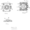
- Figures 1a and b illustrate respectively above and below perspective views of a base plate of the present invention;
- Figures 2 (a-c) show schematic views of the base plate of Figure 1;
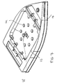
- Figure 3 (a) shows an above perspective view of a platen of the present invention, Figures 3 (b) and (c) show schematic views of this platen;
- Figures 4 (a-d) show perspective and schematic views of the latch of the present invention;
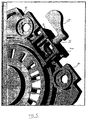
- Figure 5 shows a perspective view of the latch of Figure 4 in its mounted position in the base plate;
- Figure 6 shows an above perspective view of the base plate, platen and latch all coupled together;
- Figure 7 shows a perspective view of an alternative platen to that of Figure 3, this alternative platen having only once locking member, and;
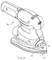
- Figure 8 shows a perspective view of a power tool including a releasable locking mechanism according to the present invention.
-
- Referring firstly to Figures 1 and 2, there can be seen a first member, in this example a
base plate 2 for a powered sander. Although not shown in these Figures, the sander to which the base plate is permanently mounted imparts to thebase plate 2 an orbital vibrating action. Thebase plate 2 is mounted to the sander by way of mountinglugs 4. Thebase plate 2 includes two housings, anopen housing 6 anddetent housing 8. As can be seen more clearly from Figure 1b, theopen housing 6 has an underside which defines ahollow opening 10. The purpose of thishollow opening 10 will become clear hereafter. Thedetent housing 8 serves to encapsulate a detent means which will also be described below. - In use of the sanding device, the orbital oscillating motion imparted to the
base plate 2 is imparted via the axis A-A as seen in Figure 1a. In order for this motion to be itself imparted to a second member of the tool, in this example asanding platen 12 as shown by referring now also to Figures 3, there needs to be some method of coupling thebase plate 2 to thesanding platen 12. - It will be seen from Figures 3a to c that the
sanding platen 12 has a generally smoothing-iron shapedouter profile 14. This is of well known shape and is used generally within the art of sanding. This will not be described any further herein. Thesanding platen 12 also has an inner peripheral shape defined by arecess 16. It will be seen by comparing the recess of Figures 3 with the outer profile of thebase plate 2 of Figures 1 and 2, that therecess 16 is designed to mate with thebase plate 2. Indeed thebase plate 2 fits snugly within therecess 16. - Considering in more detail the
sanding platen 12 of Figures 3a to c, it can be seen that within therecess 16 there is arranged at least one locking member, in this example twoprotrusions 18. It will be further appreciated that when thebase plate 2 is snugly fitted within therecess 16 then one of theprotrusions 18 will sit within thedetent housing 8 and theother protrusion 18 will sit within thehollow opening 10. - It will be understood from the drawings of Figure 3 that the
underside 20 of theplaten 12 will carry a sheet of sandpaper in conventional manner. Those skilled in the art will understand that such sandpaper often has a series of holes punched therein in order to aid dust extraction and therefore theplaten 12 hascorresponding holes 22 formed therein in order to be aligned with corresponding holes in the sanding paper (not shown). - It will be appreciated that the
sanding platen 12 of Figures 3 a-c may be coupled to thebase plate 2 in one of two orientations. That is to say either one of theprotrusions 18 may, when thebase plate 2 is snugly fitted within therecess 16, fit within either thedetent housing 8 or thehollow opening 10. - Referring now to Figures 4 a-d, it will be explained how the detent means of the present invention operates. In Figure 4 there is illustrated a detent means shown generally as 24 which, in this example comprises a latch formed as an
annulus 26 having agroove 28 of varying width formed therein. The varying width of thegroove 28 may best be seen from Figure 4d. In a preferred embodiment, the width of thegroove 28 varies linearly so as to either reduce or increase along the circumference of theannulus 26. - By referring now also to Figures 5 and 6 it can be seen how the detent means 24 is permanently housed within the
detent housing 8 so as to enable utility of the present invention. It can be seen more clearly from Figure 5 that thedetent housing 8 has acollar 30 formed therein. Within thiscollar 30 theneck 32 of the detent means 24 is arranged to sit. It will be seen that the detent means 24 is rotatable about theneck 32 thereby to also rotate theannulus 26 and therefore thegroove 28. - Coupling of the
base plate 2 to theplaten 12 is achieved as follows. Most clearly shown from Figure 3c it will be seen that eachprotrusion 18 comprises anelongate stem 34 terminating in anend cap 36. It will also be appreciated that the cross sectional area of theelongate stem 34 is smaller than the cross sectional area of theend cap 36. By rotating the detent means 24 to a position where thegroove 28 is positioned above the or eachprotrusion 18, coupling between thebase plate 2 and theplaten 12 may be effected. It will be understood that thegroove 28 of varying width along the circumference of theannulus 26 must have the following characteristics. Firstly one end of thegroove 28 must be of width larger than the cross sectional area of theelongate stem 34 and the other end of thecircumferential groove 28 must be of width smaller than the cross sectional area either of thestem 34 or of theend cap 36. In this manner therefore with correct alignment of thegroove 28 over theprotrusion 18, thebase plate 2 may be positioned into a snug fitting within therecess 16 of theplaten 12. The user may then rotate the detent means 24 so as to cause thegroove 28 to catch in a position around theelongate stem 34 but below theend cap 36 and thereby on continued rotation of the detent means 24 cause either thestem 34 or theend cap 36 to be held within thegroove 28. - It will be appreciated therefore that release of the
platen 12 from thebase plate 2 cannot be achieved until rotation of the detent means 24 back to its original position occurs whereby the width of thegroove 28 is not sufficiently narrow to prevent passage there through of theend cap 36 of theprotrusion 18. - It will be appreciated that a more secure coupling of the
base plate 2 to theplaten 12 may be achieved if, for example, the radial distance of thegroove 28 from the centre of theannulus 26 varies along the length of thegroove 28. In this way a cam mechanism may be achieved by which theend cap 36 may be pulled up toward thedetent housing 8 as thelatch 24 is rotated so as to cause a reduction of this distance. - Those skilled in the art will appreciate that the manually
operable detent 26 disclosed here above enables operation to be achieved solely by the hands of the user without the need for a separate tools. - It will also be appreciated that whilst the present invention has been described by reference to a powered sander, the term power tool is sufficiently broad to encompass any type of power tool for which the present invention would find use.
- Although in the above examples two
protrusions 18 have been shown, the present invention would work with a different number for example 1, 3, 4, 5, 6, etc. Two have been shown only by way of example and this number is not meant to be limiting. It would be understood that if a different number of protrusions are used then different geometries particularly the outer peripheral shape of thebase plate 12 andrecess 16 will be needed but this is not beyond the capability of one skilled in the art. As an example of a different number ofprotrusions 18, Figure 7, shows analternative base plate 2 to that of Figure 2. In Figure 7, like components are similarly numbered as compared to Figure 2. It will be noted, however, that only oneprotrusion 18 is present in this example. - Figure 8 shows a perspective view of a power tool, in this case a
powered sander 40, including a releasable locking mechanism according to the present invention.
Claims (12)
- A releasable locking mechanism for a power tool configured to couple a first member (2) of the tool to a second member (12) of the tool and comprising: manually operable detent means (24) mounted on one of the first (2) and second (12) members, at least one locking member (18) arranged for co-operation with the detent means (24) and mounted on the other of the first (2) and second (12) members; the first (2) and second (12) members, when coupled, being held rigidly to one another and arranged to be selectively coupled to one another in more than one orientation via the detent means (24) and the at least one locking member (18), which detent means (24) and the at least one locking member (18) are permanently attached to their respective first (2) or second (12) members on which they are mounted, thereby to achieve coupling of the first (2) and second (12) members without the need for separate tools; the mechanism characterised by the detent means (24) being rotatable to couple with the at least one locking member (18) and including a cam mechanism (26, 28) for urging the detent means (24) into closer coupling with the at least one locking member (18) upon continued rotation of the detent means (24).
- A releasable locking mechanism as claimed in claim 1 wherein the detent means (24) comprises a latch (24) movably secured within a housing (8) and having a groove (28) of varying width formed therein.
- A releasable locking mechanism as claimed in claim 2 wherein the latch is formed as an annulus (126) and the groove of varying width is circumferentially formed around this annulus (26).
- A releasable locking mechanism as claimed in any one of the preceding claims wherein the at least one locking member (18) comprises a protrusion on the other of the first and second members.
- A releasable locking member as claimed in claim 4 wherein the protrusion comprises an elongate stem (34) bearing an end cap (36), the end cap having a cross-sectional area larger than the cross-sectional area of the elongate stem.
- A releasable detent means as claimed in claim 5 wherein the cross-sectional area of the elongate stem (34) fits within any portion of the groove (28) of the latch, but the cross-sectional area of the end cap (36) is too large to fit within a portion of the groove.
- A releasable locking mechanism as claimed in any one of the preceding claims and wherein mounted on the other of the first and second members are a plurality of locking members.
- A releasable locking mechanism according to claim 7 wherein the first and second members may be coupled to one another in either of two differing orientations, these being 180° apart.
- A releasable locking mechanism according to claim 8 wherein the distance of the circumferential groove from the centre of the annulus varies along the length of the groove.
- A releasable locking mechanism according to any one of the preceding claims wherein the first member of the tool comprises a base plate and the second member comprises a platen arranged to be mounted around the base plate.
- A power tool including a releasable locking mechanism according to any one of claims 1 to 10.
- A power tool according to claim 11 wherein the power tool comprises a sander.
Applications Claiming Priority (2)
| Application Number | Priority Date | Filing Date | Title |
|---|---|---|---|
| GB9713066 | 1997-06-21 | ||
| GBGB9713066.0A GB9713066D0 (en) | 1997-06-21 | 1997-06-21 | Releasable locking mechanism |
Publications (3)
| Publication Number | Publication Date |
|---|---|
| EP0885690A2 EP0885690A2 (en) | 1998-12-23 |
| EP0885690A3 EP0885690A3 (en) | 2000-12-20 |
| EP0885690B1 true EP0885690B1 (en) | 2004-08-25 |
Family
ID=10814670
Family Applications (1)
| Application Number | Title | Priority Date | Filing Date |
|---|---|---|---|
| EP98304734A Expired - Lifetime EP0885690B1 (en) | 1997-06-21 | 1998-06-16 | Releasable locking mechanism |
Country Status (4)
| Country | Link |
|---|---|
| EP (1) | EP0885690B1 (en) |
| AT (1) | ATE274397T1 (en) |
| DE (1) | DE69825819T2 (en) |
| GB (1) | GB9713066D0 (en) |
Families Citing this family (4)
| Publication number | Priority date | Publication date | Assignee | Title |
|---|---|---|---|---|
| DE10046063B4 (en) * | 2000-09-18 | 2008-11-20 | Hilti Aktiengesellschaft | Hand grinder with sanding pad |
| DE10134296B4 (en) * | 2001-07-14 | 2010-01-28 | Hilti Aktiengesellschaft | Hand-guided grinding machine |
| US7101267B2 (en) * | 2004-11-16 | 2006-09-05 | Choon Nang Electrical Appliance Mfy., Ltd. | Tool holder for power tool |
| CN107756202B (en) * | 2016-08-15 | 2023-12-08 | 苏州宝时得电动工具有限公司 | Sander |
Family Cites Families (2)
| Publication number | Priority date | Publication date | Assignee | Title |
|---|---|---|---|---|
| US4869564A (en) * | 1988-08-24 | 1989-09-26 | Nova Office Furniture, Inc. | Modular furniture |
| US5554066A (en) * | 1995-02-09 | 1996-09-10 | Proter-Cable Corporation | In-line profile sander |
-
1997
- 1997-06-21 GB GBGB9713066.0A patent/GB9713066D0/en not_active Ceased
-
1998
- 1998-06-16 EP EP98304734A patent/EP0885690B1/en not_active Expired - Lifetime
- 1998-06-16 DE DE69825819T patent/DE69825819T2/en not_active Expired - Fee Related
- 1998-06-16 AT AT98304734T patent/ATE274397T1/en not_active IP Right Cessation
Also Published As
| Publication number | Publication date |
|---|---|
| EP0885690A3 (en) | 2000-12-20 |
| DE69825819T2 (en) | 2005-09-01 |
| ATE274397T1 (en) | 2004-09-15 |
| GB9713066D0 (en) | 1997-08-27 |
| DE69825819D1 (en) | 2004-09-30 |
| EP0885690A2 (en) | 1998-12-23 |
Similar Documents
| Publication | Publication Date | Title |
|---|---|---|
| EP2070659B1 (en) | Power Tool with Spindle Lock | |
| JP3447287B2 (en) | Hand-held machine tool | |
| JP6625245B2 (en) | Rotating device | |
| US5482499A (en) | Sanding apparatus | |
| US6264211B1 (en) | Reciprocating saw attachment for electric drill | |
| US8784164B2 (en) | Power tool with a shield | |
| US20180093359A1 (en) | Belt sander ergonomic articulating arm belt with button release, lock, and sealed housing | |
| US20090142999A1 (en) | Transmission structure of the stone chamfering machine tool holder | |
| EP1436120A1 (en) | Mounting device for abrasive wheels | |
| EP0885690A2 (en) | Releasable locking mechanism | |
| US7293944B2 (en) | Power tool with tool bit holder operator | |
| CA2467480A1 (en) | Spindle lock for an orbital abrading or polishing tool | |
| US20090280733A1 (en) | Assembly/disassembly structure of upstanding grinding axle | |
| US6102787A (en) | Oscillating combination belt, spindle and edge sander | |
| US5099538A (en) | Miniature dual action apparatus | |
| KR200373648Y1 (en) | polishing holder structure for hand grinder | |
| KR102276986B1 (en) | Grinder holder that polishing pad can be attached or detached by one-action | |
| KR200376952Y1 (en) | polishing holder structure for hand grinder | |
| WO2022077899A1 (en) | Quick clamping device and multifunctional machine tool using same | |
| US5402605A (en) | Oscillating sander | |
| US4823514A (en) | Air grinder motor vibrating sanding accessory for auto body work and the like | |
| JP3023319B2 (en) | Clamp mechanism for electric grinding machine | |
| SK189699A3 (en) | Internal abrasive machine | |
| JP3117368U (en) | Hand grinder polishing holder attachment / detachment structure | |
| JP4558154B2 (en) | Eccentricity adjustment device |
Legal Events
| Date | Code | Title | Description |
|---|---|---|---|
| PUAI | Public reference made under article 153(3) epc to a published international application that has entered the european phase |
Free format text: ORIGINAL CODE: 0009012 |
|
| AK | Designated contracting states |
Kind code of ref document: A2 Designated state(s): AT BE CH DE DK ES FI FR GB GR IE IT LI LU NL PT SE |
|
| AX | Request for extension of the european patent |
Free format text: AL;LT;LV;MK;RO;SI |
|
| PUAL | Search report despatched |
Free format text: ORIGINAL CODE: 0009013 |
|
| AK | Designated contracting states |
Kind code of ref document: A3 Designated state(s): AT BE CH CY DE DK ES FI FR GB GR IE IT LI LU MC NL PT SE |
|
| AX | Request for extension of the european patent |
Free format text: AL;LT;LV;MK;RO;SI |
|
| 17P | Request for examination filed |
Effective date: 20010202 |
|
| AKX | Designation fees paid |
Free format text: AT BE CH DE DK ES FI FR GB GR IE IT LI LU NL PT SE |
|
| 17Q | First examination report despatched |
Effective date: 20030922 |
|
| GRAP | Despatch of communication of intention to grant a patent |
Free format text: ORIGINAL CODE: EPIDOSNIGR1 |
|
| GRAS | Grant fee paid |
Free format text: ORIGINAL CODE: EPIDOSNIGR3 |
|
| GRAA | (expected) grant |
Free format text: ORIGINAL CODE: 0009210 |
|
| AK | Designated contracting states |
Kind code of ref document: B1 Designated state(s): AT BE CH DE DK ES FI FR GB GR IE IT LI LU NL PT SE |
|
| PG25 | Lapsed in a contracting state [announced via postgrant information from national office to epo] |
Ref country code: NL Free format text: LAPSE BECAUSE OF FAILURE TO SUBMIT A TRANSLATION OF THE DESCRIPTION OR TO PAY THE FEE WITHIN THE PRESCRIBED TIME-LIMIT Effective date: 20040825 Ref country code: LI Free format text: LAPSE BECAUSE OF FAILURE TO SUBMIT A TRANSLATION OF THE DESCRIPTION OR TO PAY THE FEE WITHIN THE PRESCRIBED TIME-LIMIT Effective date: 20040825 Ref country code: IT Free format text: LAPSE BECAUSE OF FAILURE TO SUBMIT A TRANSLATION OF THE DESCRIPTION OR TO PAY THE FEE WITHIN THE PRE;WARNING: LAPSES OF ITALIAN PATENTS WITH EFFECTIVE DATE BEFORE 2007 MAY HAVE OCCURRED AT ANY TIME BEFORE 2007. THE CORRECT EFFECTIVE DATE MAY BE DIFFERENT FROM THE ONE RECORDED.SCRIBED TIME-LIMIT Effective date: 20040825 Ref country code: FI Free format text: LAPSE BECAUSE OF FAILURE TO SUBMIT A TRANSLATION OF THE DESCRIPTION OR TO PAY THE FEE WITHIN THE PRESCRIBED TIME-LIMIT Effective date: 20040825 Ref country code: CH Free format text: LAPSE BECAUSE OF FAILURE TO SUBMIT A TRANSLATION OF THE DESCRIPTION OR TO PAY THE FEE WITHIN THE PRESCRIBED TIME-LIMIT Effective date: 20040825 Ref country code: BE Free format text: LAPSE BECAUSE OF FAILURE TO SUBMIT A TRANSLATION OF THE DESCRIPTION OR TO PAY THE FEE WITHIN THE PRESCRIBED TIME-LIMIT Effective date: 20040825 Ref country code: AT Free format text: LAPSE BECAUSE OF FAILURE TO SUBMIT A TRANSLATION OF THE DESCRIPTION OR TO PAY THE FEE WITHIN THE PRESCRIBED TIME-LIMIT Effective date: 20040825 |
|
| REG | Reference to a national code |
Ref country code: GB Ref legal event code: FG4D |
|
| REG | Reference to a national code |
Ref country code: CH Ref legal event code: EP |
|
| REG | Reference to a national code |
Ref country code: IE Ref legal event code: FG4D |
|
| REF | Corresponds to: |
Ref document number: 69825819 Country of ref document: DE Date of ref document: 20040930 Kind code of ref document: P |
|
| PG25 | Lapsed in a contracting state [announced via postgrant information from national office to epo] |
Ref country code: SE Free format text: LAPSE BECAUSE OF FAILURE TO SUBMIT A TRANSLATION OF THE DESCRIPTION OR TO PAY THE FEE WITHIN THE PRESCRIBED TIME-LIMIT Effective date: 20041125 Ref country code: GR Free format text: LAPSE BECAUSE OF FAILURE TO SUBMIT A TRANSLATION OF THE DESCRIPTION OR TO PAY THE FEE WITHIN THE PRESCRIBED TIME-LIMIT Effective date: 20041125 Ref country code: DK Free format text: LAPSE BECAUSE OF FAILURE TO SUBMIT A TRANSLATION OF THE DESCRIPTION OR TO PAY THE FEE WITHIN THE PRESCRIBED TIME-LIMIT Effective date: 20041125 |
|
| PG25 | Lapsed in a contracting state [announced via postgrant information from national office to epo] |
Ref country code: ES Free format text: LAPSE BECAUSE OF FAILURE TO SUBMIT A TRANSLATION OF THE DESCRIPTION OR TO PAY THE FEE WITHIN THE PRESCRIBED TIME-LIMIT Effective date: 20041206 |
|
| REG | Reference to a national code |
Ref country code: CH Ref legal event code: PL |
|
| NLV1 | Nl: lapsed or annulled due to failure to fulfill the requirements of art. 29p and 29m of the patents act | ||
| PG25 | Lapsed in a contracting state [announced via postgrant information from national office to epo] |
Ref country code: LU Free format text: LAPSE BECAUSE OF NON-PAYMENT OF DUE FEES Effective date: 20050616 Ref country code: IE Free format text: LAPSE BECAUSE OF NON-PAYMENT OF DUE FEES Effective date: 20050616 |
|
| ET | Fr: translation filed | ||
| PLBE | No opposition filed within time limit |
Free format text: ORIGINAL CODE: 0009261 |
|
| STAA | Information on the status of an ep patent application or granted ep patent |
Free format text: STATUS: NO OPPOSITION FILED WITHIN TIME LIMIT |
|
| 26N | No opposition filed |
Effective date: 20050526 |
|
| REG | Reference to a national code |
Ref country code: IE Ref legal event code: MM4A |
|
| PGFP | Annual fee paid to national office [announced via postgrant information from national office to epo] |
Ref country code: DE Payment date: 20070731 Year of fee payment: 10 |
|
| PGFP | Annual fee paid to national office [announced via postgrant information from national office to epo] |
Ref country code: GB Payment date: 20070628 Year of fee payment: 10 |
|
| PG25 | Lapsed in a contracting state [announced via postgrant information from national office to epo] |
Ref country code: PT Free format text: LAPSE BECAUSE OF NON-PAYMENT OF DUE FEES Effective date: 20050125 |
|
| PGFP | Annual fee paid to national office [announced via postgrant information from national office to epo] |
Ref country code: FR Payment date: 20070618 Year of fee payment: 10 |
|
| GBPC | Gb: european patent ceased through non-payment of renewal fee |
Effective date: 20080616 |
|
| REG | Reference to a national code |
Ref country code: FR Ref legal event code: ST Effective date: 20090228 |
|
| PG25 | Lapsed in a contracting state [announced via postgrant information from national office to epo] |
Ref country code: DE Free format text: LAPSE BECAUSE OF NON-PAYMENT OF DUE FEES Effective date: 20090101 |
|
| PG25 | Lapsed in a contracting state [announced via postgrant information from national office to epo] |
Ref country code: GB Free format text: LAPSE BECAUSE OF NON-PAYMENT OF DUE FEES Effective date: 20080616 |
|
| PG25 | Lapsed in a contracting state [announced via postgrant information from national office to epo] |
Ref country code: FR Free format text: LAPSE BECAUSE OF NON-PAYMENT OF DUE FEES Effective date: 20080630 |