EP0885081B1 - Direct drive multiple axes rotary spindle head for milling machine - Google Patents
Direct drive multiple axes rotary spindle head for milling machine Download PDFInfo
- Publication number
- EP0885081B1 EP0885081B1 EP96919437A EP96919437A EP0885081B1 EP 0885081 B1 EP0885081 B1 EP 0885081B1 EP 96919437 A EP96919437 A EP 96919437A EP 96919437 A EP96919437 A EP 96919437A EP 0885081 B1 EP0885081 B1 EP 0885081B1
- Authority
- EP
- European Patent Office
- Prior art keywords
- spindle
- axis
- rotation
- fork
- rotor
- Prior art date
- Legal status (The legal status is an assumption and is not a legal conclusion. Google has not performed a legal analysis and makes no representation as to the accuracy of the status listed.)
- Expired - Lifetime
Links
Images


Classifications
-
- B—PERFORMING OPERATIONS; TRANSPORTING
- B23—MACHINE TOOLS; METAL-WORKING NOT OTHERWISE PROVIDED FOR
- B23Q—DETAILS, COMPONENTS, OR ACCESSORIES FOR MACHINE TOOLS, e.g. ARRANGEMENTS FOR COPYING OR CONTROLLING; MACHINE TOOLS IN GENERAL CHARACTERISED BY THE CONSTRUCTION OF PARTICULAR DETAILS OR COMPONENTS; COMBINATIONS OR ASSOCIATIONS OF METAL-WORKING MACHINES, NOT DIRECTED TO A PARTICULAR RESULT
- B23Q1/00—Members which are comprised in the general build-up of a form of machine, particularly relatively large fixed members
- B23Q1/25—Movable or adjustable work or tool supports
- B23Q1/44—Movable or adjustable work or tool supports using particular mechanisms
- B23Q1/50—Movable or adjustable work or tool supports using particular mechanisms with rotating pairs only, the rotating pairs being the first two elements of the mechanism
- B23Q1/54—Movable or adjustable work or tool supports using particular mechanisms with rotating pairs only, the rotating pairs being the first two elements of the mechanism two rotating pairs only
- B23Q1/5406—Movable or adjustable work or tool supports using particular mechanisms with rotating pairs only, the rotating pairs being the first two elements of the mechanism two rotating pairs only a single rotating pair followed perpendicularly by a single rotating pair
- B23Q1/5412—Movable or adjustable work or tool supports using particular mechanisms with rotating pairs only, the rotating pairs being the first two elements of the mechanism two rotating pairs only a single rotating pair followed perpendicularly by a single rotating pair followed perpendicularly by a single rotating pair
-
- B—PERFORMING OPERATIONS; TRANSPORTING
- B23—MACHINE TOOLS; METAL-WORKING NOT OTHERWISE PROVIDED FOR
- B23Q—DETAILS, COMPONENTS, OR ACCESSORIES FOR MACHINE TOOLS, e.g. ARRANGEMENTS FOR COPYING OR CONTROLLING; MACHINE TOOLS IN GENERAL CHARACTERISED BY THE CONSTRUCTION OF PARTICULAR DETAILS OR COMPONENTS; COMBINATIONS OR ASSOCIATIONS OF METAL-WORKING MACHINES, NOT DIRECTED TO A PARTICULAR RESULT
- B23Q2210/00—Machine tools incorporating a specific component
- B23Q2210/004—Torque motors
-
- B—PERFORMING OPERATIONS; TRANSPORTING
- B23—MACHINE TOOLS; METAL-WORKING NOT OTHERWISE PROVIDED FOR
- B23Q—DETAILS, COMPONENTS, OR ACCESSORIES FOR MACHINE TOOLS, e.g. ARRANGEMENTS FOR COPYING OR CONTROLLING; MACHINE TOOLS IN GENERAL CHARACTERISED BY THE CONSTRUCTION OF PARTICULAR DETAILS OR COMPONENTS; COMBINATIONS OR ASSOCIATIONS OF METAL-WORKING MACHINES, NOT DIRECTED TO A PARTICULAR RESULT
- B23Q2220/00—Machine tool components
- B23Q2220/006—Spindle heads
-
- Y—GENERAL TAGGING OF NEW TECHNOLOGICAL DEVELOPMENTS; GENERAL TAGGING OF CROSS-SECTIONAL TECHNOLOGIES SPANNING OVER SEVERAL SECTIONS OF THE IPC; TECHNICAL SUBJECTS COVERED BY FORMER USPC CROSS-REFERENCE ART COLLECTIONS [XRACs] AND DIGESTS
- Y10—TECHNICAL SUBJECTS COVERED BY FORMER USPC
- Y10T—TECHNICAL SUBJECTS COVERED BY FORMER US CLASSIFICATION
- Y10T409/00—Gear cutting, milling, or planing
- Y10T409/30—Milling
- Y10T409/306664—Milling including means to infeed rotary cutter toward work
- Y10T409/307672—Angularly adjustable cutter head
-
- Y—GENERAL TAGGING OF NEW TECHNOLOGICAL DEVELOPMENTS; GENERAL TAGGING OF CROSS-SECTIONAL TECHNOLOGIES SPANNING OVER SEVERAL SECTIONS OF THE IPC; TECHNICAL SUBJECTS COVERED BY FORMER USPC CROSS-REFERENCE ART COLLECTIONS [XRACs] AND DIGESTS
- Y10—TECHNICAL SUBJECTS COVERED BY FORMER USPC
- Y10T—TECHNICAL SUBJECTS COVERED BY FORMER US CLASSIFICATION
- Y10T409/00—Gear cutting, milling, or planing
- Y10T409/30—Milling
- Y10T409/30784—Milling including means to adustably position cutter
- Y10T409/308512—Compound angular adjustment
Definitions
- the present invention relates to a machine tool and, more particularly, to a gearless operating spindle head for a milling machine which is equipped with motors coupled to the spindle and spindle head of such machine for directly driving and controlling the rotation of such spindle and spindle head about multiple axes.
- the present invention is a gearless direct drive rotary head for a machine tool spindle comprising a gimbal assembly mounting a spindle for rotation about a plurality of axes and a plurality of motors coupled to the gimbal assembly and the spindle for directly driving and controlling the rotation of the gimbal assembly and the spindle about the plurality of axes respectively.
- the gimbal assembly includes a fork mounted for rotation about a first axis which includes a pair of spaced fork arms, a spindle mounted between the fork arms for rotation about a second axis, a first motor coupled to the fork for directly driving and controlling the rotation of the fork about the first axis, and a second motor coupled to the spindle for directly driving and controlling the rotation of the spindle about the second axis.
- the fork is mounted on a support arm which includes a rotatable sleeve concentric with the first axis and operably coupled to the fork for rotation therewith.
- the support arm further includes a housing for the motor.
- the motor comprises a servo motor which is mounted within the housing and surrounds the sleeve concentric with the first axis.
- the motor includes a rotor rotatable and concentric about the first axis which is coupled to the sleeve for directly driving and controlling the rotation of the sleeve about the first axis.
- each of the fork arms includes a hollow housing with which a second motor is mounted.
- Each second motor comprises a servo motor mounted in the housing in the fork arms respectively and concentric with the second axis.
- Each of the second motors includes a rotor rotatable and concentric about the second axis.
- Each of the rotors is coupled to opposite sides of the spindle respectively for directly driving and controlling the rotation of the spindle about the second axis.
- the gimbal assembly further includes a spindle housing which mounts the spindle for rotation about a third axis and a third motor coupled to the spindle for directly driving and controlling the rotation of the spindle about the third axis.
- the direct drive motors replace the conventional gears and timing belts which have been coupled to the spindle and spindle head for controlling the rotation of the spindle and spindle head.
- the directly coupled motors allow the spindle to be rotated at high speeds in response to the abrupt and continuous changes in the contour of the surface being machined so as to maintain the required angular relationship between the spindle head and such surface.
- Another advantage is the tool stiffness achieved through the elimination of gears. Yet another advantage is the elimination of the power losses which occur when power is transmitted through gear trains.
- spindle head embodying the present invention is described hereinbelow in its usual assembled position as shown in the accompanying drawings and terms such as upper, lower, horizontal, etc., will be used herein with reference to this usual position.
- spindle head of this invention is used with certain conventional components the details of which, although not fully illustrated or described, will be apparent to those having skill in the art and an understanding of the necessary functions of such components.
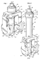
- Head 10 includes a gimbal assembly 12 which allows a spindle assembly 22 mounted thereon to be rotated about multiple axes as described below.
- Gimbal assembly 12 includes a fork 14 which is mounted to a multi-functional machine tool such as a milling machine (not shown) or the like for rotation about a first vertical axis C passing centrally and longitudinally through fork 14.
- Fork 14 includes a top horizontal base 16 and two spaced apart elongate arms 18 and 20 extending vertically downwardly perpendicularly from the ends of base 16 and unitary therewith.
- the spindle assembly 22 is mounted between the fork arms 18 and 20 for rotation about a second horizontal axis A passing horizontally through the fork arms 18 and 20.
- Spindle assembly 22 includes an elongate spindle 24 mounted within a spindle housing 26 (FIGURE 7).
- a motor (not shown) in spindle 24 operates in a known way to rotate a milling or cutting tool 28 held in a tool holder (not shown) secured within the distal end of spindle 24.
- a motor assembly 30 is mounted and coupled to the top of base 16 of fork 14 for directly driving and controlling the rotation of fork 14 about vertical axis C.
- Another motor assembly 90 (FIGURE 4) is mounted inside fork arms 18 and 20 and coupled to spindle assembly 22 for directly driving and controlling the rotation of the spindle assembly 22 about horizontal axis A.
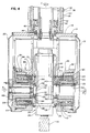
- FIGURE 2 depicts the spindle head 10 of FIGURE 1 additionally including a vertically extending elongate cylindrical support arm 32, mounted between motor assembly 30 and fork 14, and having a longitudinal axis concentric with axis C.
- support arm 32 includes an elongate outer cylindrical sleeve 34, an elongate inner rotatable cylindrical sleeve 36 and an elongate cylindrical cartridge 38 disposed between outer sleeve 34 and inner sleeve 36.
- Each of the sleeves 34 and 36 and the cartridge 38 have longitudinal axes concentric with vertical axis C.
- Inner sleeve 36 includes inner and outer cylindrical surfaces 37 and 39 and is journalled for rotation about axis C by bearing assemblies 40 comprising bearing rollers 41 carried by bearing races 42 which are secured to sleeve 36 and cartridge 38.
- sleeve 36 includes a bottom circumferential annular end 44 which is coupled and secured to the top of base 16 of fork 14 by a plurality of fasteners 46 extending circumferentially around and between end 44 and base 16.
- motor assembly 30 is operably coupled to the top of sleeve 36 for directly driving and controlling the rotation of sleeve 36 about axis C and thus the rotation of fork 14 operably coupled thereto.
- support arm 32 includes a housing 48 for the motor assembly 30.
- Housing 48 is comprised of a outer cylindrically shaped jacket 50 which is spaced from and extends circumferentially around sleeve 36 and top and bottom circumferentially extending annular end plates 52 and 54 which are fastened with screws 56 to the opposite end faces of jacket 50.
- Sleeve 36 is journalled for rotation about housing 48 by bearing assemblies 60 comprising ball bearings 61 supported by bearing races 62 secured to sleeve 36 and the inner circumferential face 64 of end plate 54.
- motor assembly 30 comprises a frameless, high torque servo motor 31 which surrounds sleeve 36 concentric with axis C and is mounted within the interior of housing 48 and, more particularly within the jacket 50 thereof.
- Motor 31 can be, frameless, high torque servo motor including, among other known elements, a stator 66, a rotatable mount 68 disposed inwardly of stator 66 for mounting a rotatable rotor 70 operably coupled to and abutting mount 68 and disposed between mount 68 and stator 66, a sleeve clamp 69 disposed inwardly of and abutting mount 68 and operably coupled to and abutting inner sleeve 36, and abutting rotors 72 and 74 disposed inwardly of stator 66 and, more particularly, inwardly of sleeve 36.
- a driver slip ring 71 disposed inwardly of and abutting rotor 74 and inside sleeve 36, is coupled to sleeve 36 by means of fasteners such as screws 82.
- Rotors 72 and 74 are rotatable and concentric about axis C.
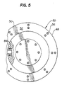
- Rotor 72 additionally includes an outer surface 76 abutting the inner surface 37 of sleeve 36 and an end with a radially outwardly circumferentially extending annular shoulder 78 which is seated on and coupled to the end face 48 of sleeve 36.
- a plurality of fasteners such as screws 80 extend through and between shoulder 78 and end face 48 for coupling and securing rotor 72 to sleeve 36 and for directly driving and controlling the rotation of sleeve 36 about axis C.
- numerical controls associated with the milling machine activate motor 31 to cause the rotation of sleeve 36 and thus fork 14.
- the position and velocity of rotor 72 and thus sleeve 36 is detected and monitored by an angle encoder 84 which is mounted within housing 48 and operably coupled to rotor 72 and the machine's numerical controls.
- the sleeve clamp 69 is used to lock the inner sleeve 36 into position after the sleeve 36 has been rotated a desired amount to rotate the fork 14 a desired amount.
- motor assembly 90 comprises motors 92 and 94 mounted respectively in the fork arms 18 and 20 concentric with horizontal axis A.
- the motors 92 and 94 are coupled to opposite sides of the spindle assembly 22 for directly driving and controlling the rotation of the spindle assembly 22 about axis A.
- motor assembly 90 could alternatively comprise one of the motors 92 and 94 mounted in one of the fork arms 18 and 20 and coupled to one of the sides of the spindle assembly 22 for directly driving and controlling the rotation of the spindle assembly 22 about axis A. Further, motor assembly 90 could also alternatively comprise one of the motors 92 and 94 split into first and second halves mounted in the fork arms 18 and 20 respectively and coupled to the opposite sides of spindle assembly 22.
- motors 92 and 94 are housed in hollow cylindrical members 96 and 98 respectively in fork arms 18 and 20 respectively.
- Each of the cylindrical members 96 and 98 includes inner and outer end faces 99 and 100 respectively and an inner cylindrical surface 101 therebetween which defines a housing for the motors 92 and 94 respectively.
- Cylindrical inner surface 101 includes cylindrical portions 102, 104, 106 and 108. Portions 102 and 104 are separated from each other by a wall extending circumferentially radially inwardly between portions 102 and 104 which defines a shoulder 110. Portions 104 and 106 are separated from each other by a wall extending circumferentially radially inwardly between portions 104 and 106 which defines a shoulder 114. Portions 106 and 108 are separated from each other by a wall extending circumferentially inwardly between portions 106 and 108 which defines a shoulder 118.
- Each of the motors 92 and 94 can also be an frameless, high torque servo motor including, among other known elements, a stator 120, a shaft motor 122 disposed inwardly of the stator 120, a sleeve clamp 124 disposed inwardly of and abutting the shaft motor 122, a revolving rotor 126 disposed inwardly of and abutting the sleeve clamp 124, and a stationary rotor 128 disposed inwardly of and abutting the revolving rotor 126.
- the rotor 126 in each of the motors 92 and 94 is mounted for rotation concentric with horizontal axis A and includes a radially inwardly extending annular wall 130 having a neck 132 extending axially outwardly and unitary therewith.
- the wall 130 of the rotor 126 of motor 92 extends only partially radially inwardly while the wall 130 of rotor 126 of motor 94 extends completely radially inwardly to allow the coupling of an encoder shaft 148 thereto.
- Motors 92 and 94 are positioned in members 96 and 98 respectively such that portions of the motors abut the inner cylindrical surface 101 and shoulders 110 and 114 thereof and, more particularly, such that the stator 120 thereof abuts portion 102 and shoulder 110 of cylindrical surface 101. Moreover, motors 92 and 94 are secured in members 96 and 98 respectively by fasteners such as screws 113 extending between motor brackets 111 on the motors 92 and 94 respectively and shoulder 114 of members 96 and 98 respectively.
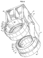
- spindle housing 26 includes an inner cylindrical surface 133 defining a housing for spindle 24 and an outer cylindrical surface 134 having a pair of diametrically opposed rectangularly shaped rotor mounting blocks 136 and 138 formed unitary thereon.
- Each of the blocks 136 and 138 has an outer flat surface 140 and an cylindrical aperture 142 therein aligned concentric with axis A and extending between the outer surface 140 of blocks 136 and 138 and the inner surface 133 of spindle housing 26.
- the spindle assembly 22 is positioned and coupled between fork arms 18 and 20 such that the blocks 136 and 138 are aligned with the members 96 and 98 respectively and, more particularly, such that the outer surface 140 of blocks 136 and 138 abuts the inner surface 99 and shoulder 118 of the members 96 and 98 respectively.
- the rotor 126 of each of the motors 92 and 94 is coupled directly to the blocks 136 and 138 respectively such that the annular end wall 130 of the rotor 126 abuts the outer surface 140 of blocks 136 and 138 respectively and the neck 132 on the rotor 126 is fitted into the aperture 142 in blocks 136 and 138 respectively for directly driving and controlling the rotation of spindle assembly 22 about axis A.
- the rotor 126 on each of the motors 92 and 94 is securely fastened to the blocks 136 and 138 respectively with fasteners such as screws 144 which extend between the annular end wall 130 of the rotor 126 and the blocks 136 and 138 respectively.
- the present invention encompasses not only the use of motors to directly drive and control the rotation of a spindle and spindle head about two axis (FIGURES 1 and 2) but also the use of motors to directly drive and control the rotation of a spindle and spindle head about additional axes such as the D axis exemplified in the spindle head embodiment of FIGURE 8.
- FIGURE 8 depicts an alternate simplified embodiment of a gearless, direct drive, multiple axes rotary head 200 embodying the features of the present invention.
- Head 200 differs from head 10 in that it incorporates a gimbal assembly 212 adapted to rotate spindle assembly 222 about three different orthogonal axes A, C and D, rather than just axes A and C as with gimbal assembly 12 of head 10.
- the rotation of spindle 224 about axis D is provided by mounting the spindle 224 in a spindle housing 226 including a cavity 227 within which spindle 224 is allowed to move side-to-side.
- a motor 260 is mounted to the side of spindle housing 226 and coupled to spindle 224 for directly driving and controlling the rotation of spindle 224 about axis D.
- Motors 231, 292 and 294 operate in the same manner as motors 31, 92 and 94 respectively to directly drive and control the rotation of the fork 214 and spindle 224 respectively about the A and C axes respectively.
- the use of motors coupled directly to the spindle and spindle head, instead of gears, as in present spindle heads, to rotate the spindle and spindle head advantageously allows the spindle to be rotated at high speeds in response to the abrupt and continuous changes in the contour of a surface being machined since directly mounted motors allow for the quick acceleration and deceleration of the spindle so as to maintain the required angular relationship between the spindle head and the surface being machined.
- the use of motors instead of gears is practical, reduces the complexity of the spindle head, provides a spindle head with high mechanical stiffness and eliminates the power loss which occurs when power is transferred through gear trains.
Description
Claims (14)
- A gearless direct drive, multiple axes rotary head (10) for a machine tool spindle (24), said rotary head comprising a fork (14) mounted for rotation about a first axis (c) and including a pair of spaced fork arms; a spindle mounted between said fork arms for rotation about a second axis (A); first motor means (30) coupled to said fork for directly driving and controlling the rotation of said fork about said first axis; and second motor means (122) coupled to said spindle for directly driving and controlling the rotation of said spindle about said second axis.
- A rotary head as claimed in Claim 1 and including a support arm (32) to which said fork is mounted, said support arm including a rotatable sleeve (36) concentric with said first axis and operably coupled to said fork for rotation therewith, said support arm including a housing (48) for said first motor means and said first motor means being operably coupled to said sleeve for driving and controlling the rotation of said sleeve.
- A rotary head as claimed in Claim 2 wherein said first motor means comprises a servo motor mounted within said housing and surrounding said sleeve concentric with said first axis, said servo motor including a rotor (70) rotatable and concentric about said first axis, said rotor being coupled to said sleeve for directly driving and controlling the rotation of said sleeve about said first axis.
- A rotary head as claimed in Claim 3 wherein opposed annular circumferential end faces (64,76), said rotor has an end with a radially outwardly extending shoulder (78), said rotor abutting said sleeve and said shoulder being seated on and coupled to one of said end faces of said sleeve for directly driving and controlling the rotation of said sleeve.
- A rotary head as claimed in Claim 4 comprising a plurality of fasteners (56) extending through and between said shoulder and one of said end faces for coupling and securing said rotor to said sleeve.
- A rotary head as claimed in any preceding claim wherein each of said fork arms includes a fork arm hollow housing within which said second motor means is mounted.
- A rotary head as claimed in Claim 6 wherein said second motor means comprises a pair of servo motors (124) mounted concentric with said second axis one in each of said fork arm hollow housings, respectively, each of said motors including a rotor (128) rotatable and concentric about said second axis, each of said rotors being coupled directly to opposite sides of said spindle for driving and controlling the rotation of said spindle about said second axis.
- A rotary head as claimed in Claim 7 wherein said spindle is mounted in a spindle housing including an outer surface with a pair of diametrically opposed blocks unitary with said outer surface and aligned with said housing in said fork arms respectively, said rotor of said motors being coupled directly to said blocks respectively for driving and controlling the rotation of said spindle about said second axis.
- A rotary head as claimed in Claim 8 wherein each of said motors rotor includes a radially inwardly extending annular end wall (130) with a neck (132) extending axially outwardly and unitary therewith, each of said blocks having an outer surface and an aperture extending centrally about said second axis into said outer surface thereof, said annular end wall on said rotor of said motors abutting said outer surface of said blocks respectively and said neck on said rotor of said motors fitting into said aperture in said blocks respectively for coupling said rotor of said motors to said spindle for directly driving and controlling the rotation of said spindle about said second axis.
- A rotary head as claimed in an preceding claim wherein said first axis is orthogonal to said second axis.
- A gearless direct drive rotary head for a milling machine comprising a gimbal assembly (212) mounting a spindle (224) for rotation about a plurality of axes, and a plurality of motors (231,260,292,294) comprising at least first and second motor means and coupled to said gimbal assembly and said spindle for directly driving and controlling the rotation of said gimbal assembly and said spindle about said plurality of axes respectively.
- A rotary head as claimed in Claim 11 wherein said gimbal assembly includes a fork mounted for rotation about a first axis and including a pair of spaced fork arms, a spindle mounted between said fork arms for rotation about a second axis, first motor means coupled to said fork for directly driving and controlling the rotation of said fork about said first axis, and second motor means coupled to said spindle for directly driving and controlling the rotation of said spindle about said second axis.
- A rotary head as claimed in Claim 12 including a support arm and first motor means structured and arranged as defined in any one of Claims 2 to 4.
- A rotary head as claimed in Claim 12 wherein said gimbal assembly includes a spindle housing mounting said spindle for rotation about a third axis and a third motor means coupled to said spindle for directly driving and controlling the rotation of said spindle about said third axis (D).
Priority Applications (1)
| Application Number | Priority Date | Filing Date | Title |
|---|---|---|---|
| DE29623999U DE29623999U1 (en) | 1995-06-13 | 1996-06-13 | Directly driven, multi-axis lathe head for milling machines |
Applications Claiming Priority (3)
| Application Number | Priority Date | Filing Date | Title |
|---|---|---|---|
| US08/489,892 US5584621A (en) | 1995-06-13 | 1995-06-13 | Direct drive multiple axes rotary spindle head for milling machine |
| US489892 | 1995-06-13 | ||
| PCT/US1996/010370 WO1996041695A1 (en) | 1995-06-13 | 1996-06-13 | Direct drive multiple axes rotary spindle head for milling machine |
Publications (4)
| Publication Number | Publication Date |
|---|---|
| EP0885081A1 EP0885081A1 (en) | 1998-12-23 |
| EP0885081A4 EP0885081A4 (en) | 1998-12-23 |
| EP0885081B1 true EP0885081B1 (en) | 2001-09-12 |
| EP0885081B2 EP0885081B2 (en) | 2006-06-07 |
Family
ID=23945713
Family Applications (1)
| Application Number | Title | Priority Date | Filing Date |
|---|---|---|---|
| EP96919437A Expired - Lifetime EP0885081B2 (en) | 1995-06-13 | 1996-06-13 | Direct drive multiple axes rotary spindle head for milling machine |
Country Status (5)
| Country | Link |
|---|---|
| US (1) | US5584621A (en) |
| EP (1) | EP0885081B2 (en) |
| AU (1) | AU6178096A (en) |
| DE (1) | DE69615223T3 (en) |
| WO (1) | WO1996041695A1 (en) |
Cited By (13)
| Publication number | Priority date | Publication date | Assignee | Title |
|---|---|---|---|---|
| EP1870199A1 (en) * | 2006-06-23 | 2007-12-26 | Franz Kessler GmbH | Multi-axis pivot head for a machine tool |
| EP1880796A1 (en) * | 2006-07-18 | 2008-01-23 | Franz Kessler GmbH | Multi-axis pivot head for a machine tool |
| DE20221851U1 (en) | 2002-12-17 | 2008-07-31 | Mfs Maschinenfabrik Gmbh | Machine tool with direct drive |
| DE10300042B4 (en) * | 2003-01-03 | 2008-11-06 | Klement, Joachim, Dipl.-Ing. | High-speed spindle unit for a machine tool |
| US7470095B2 (en) | 2005-09-13 | 2008-12-30 | F. Zimmerman Gmbh | Mobile milling head with torque motor drive |
| EP2014409A1 (en) | 2007-10-24 | 2009-01-14 | WENZEL Präzision GmbH | Multi-axis swivel head with integrated controller and coordinate measuring machine with such a multi-axis swivel head |
| WO2009121387A1 (en) | 2008-03-31 | 2009-10-08 | Liebherr-Verzahntechnik Gmbh | Machining head |
| DE102008047849A1 (en) | 2008-09-18 | 2010-04-01 | Klement, Joachim, Dipl.-Ing. | Universally rotatable milling head or pivoting unit for use in e.g. aircraft industry for horizontal processing conical mold cavity, has direct drive-spherical motor for performing driving and stepless turning of B-axle |
| DE102008051613A1 (en) | 2008-10-08 | 2010-04-15 | Tramec Gmbh | Milling head i.e. two-axis milling head, has spindle assembly provided with spindle housing that is formed with set of pins, where pins are rotatably mounted concentric to axis by bearing device that is arranged in recess of bracket arm |
| DE102006005762B4 (en) * | 2005-06-09 | 2011-07-21 | Franz Kessler GmbH, 88422 | Multi-axis turret with a fluid unit |
| DE102010037737A1 (en) | 2010-09-23 | 2012-03-29 | F. Zimmermann Gmbh | Rotating head i.e. milling head, for controlled positioning of portal milling machine spindle during e.g. model construction in automobile industry, has input elements coupled with motors, and gear output element coupled with spindle device |
| WO2012052058A1 (en) | 2010-10-21 | 2012-04-26 | Imo Holding Gmbh | Milling head for a gear cutting machine and method for producing gear teeth |
| CN103286612A (en) * | 2013-06-04 | 2013-09-11 | 上海三一精机有限公司 | High-power swing head transmission structure and machine tool |
Families Citing this family (98)
| Publication number | Priority date | Publication date | Assignee | Title |
|---|---|---|---|---|
| US6019013A (en) * | 1994-10-24 | 2000-02-01 | Luik; Ilmar | Machine tool operated by gyroscopic precession |
| US5718545A (en) * | 1995-10-23 | 1998-02-17 | Husted; Ernie R. | Tool positioning device |
| US5996329A (en) * | 1998-05-15 | 1999-12-07 | Cardenas; Curtis E. | Multi-axis machining head |
| DE19845750B4 (en) * | 1998-10-05 | 2005-10-27 | Zayer S.A., Vitoria | milling head |
| EP1038630A1 (en) * | 1999-03-26 | 2000-09-27 | Industrias Anayak, S.A. | Milling head with direct drive for continuous rotations around two axles |
| DE19957659A1 (en) * | 1999-11-30 | 2001-06-07 | Hiltner Sonderteilebau | Machine tool with swiveling headstock for an auxiliary spindle |
| ES2169666B1 (en) * | 2000-05-17 | 2004-02-16 | Danobat | MACHINE RECTIFIER WITH HEAD PORTAMUELA WITH POSSIBILITY OF TURN THROUGH DIRECT DRIVING. |
| EP1205275B1 (en) * | 2000-05-25 | 2004-09-08 | TECNICHE INDUSTRIALI S.r.l. | Operating head for automatic machine tools, with projecting interchangeable chuck unit |
| EP1157777A3 (en) * | 2000-05-25 | 2002-05-22 | Mauro Colombo | Operating head for automatic machine tools |
| DE10029326A1 (en) * | 2000-06-20 | 2002-01-03 | Fotec Forschungs Und Technolog | NC-controlled portal milling machine |
| ES2171121B1 (en) * | 2000-07-06 | 2004-02-16 | Soraluce S Coop | MODULARITY AND DRIVE SYSTEM APPLICABLE TO THE BUTCHER HEAD OF A MILLING MACHINE. |
| ITVE20000020U1 (en) * | 2000-09-25 | 2002-03-25 | Fpt Ind Spa | BIROTATIVE HEAD SPINDLE HOLDER FOR MACHINE TOOL |
| DE10047917B4 (en) * | 2000-09-27 | 2004-06-03 | Siemens Ag | Gearless, integrated spindle drive for an industrial processing machine |
| ITVE20000025U1 (en) * | 2000-10-17 | 2002-04-17 | Fpt Ind Spa | BIROTATIVE HEAD SPINDLE HOLDER FOR MACHINE TOOL |
| GB0026234D0 (en) * | 2000-10-26 | 2000-12-13 | Shin Nippon Koki Company Ltd | A spindle head |
| DE10104669C5 (en) * | 2001-02-02 | 2005-12-15 | Klement, Klaus-Dieter | Drive head for NC-controlled positioning movements of a tool spindle or a workpiece table about at least one axis of rotation |
| ES2294062T3 (en) * | 2001-05-17 | 2008-04-01 | CHIRON-WERKE GMBH & CO. KG | MACHINE TOOL AND PROCEDURE FOR MECHANIZATION OF A PART TO BE PREPARED IN THE FORM OF A BAR. |
| NO315973B1 (en) * | 2001-06-21 | 2003-11-24 | Per Oeyvind Boe | Device at cutting / milling head |
| DE10149180A1 (en) * | 2001-10-04 | 2003-04-30 | Peiseler Gmbh & Co Kg | Rotary table |
| AU2003210372A1 (en) * | 2002-02-28 | 2003-09-09 | Al-Ko Kober Ag | Pivotable towing device for towing vehicles |
| DE20208792U1 (en) * | 2002-06-06 | 2003-07-24 | Niles Simmons Industrieanlagen | Rotary milling machine |
| ITBO20020400A1 (en) * | 2002-06-21 | 2003-12-22 | Jobs Spa | MACHINE TOOL |
| FR2845303B1 (en) * | 2002-10-03 | 2005-07-08 | Forest Line Albert | MULTIAXIS SWIVEL HEAD OF MACHINE TOOL |
| EP1407901B2 (en) * | 2002-10-09 | 2012-10-03 | AL-KO Kober AG | Towing hitch for towing vehicles |
| NL1021771C2 (en) * | 2002-10-29 | 2004-05-03 | Stichting Astron | Construction element, method and device for manufacturing a construction element, computer program and mirror. |
| FR2861326B3 (en) * | 2003-10-24 | 2006-02-03 | Dufieux Ind | METHOD AND DEVICE FOR MACHINING PANELS |
| US20050279870A1 (en) * | 2004-06-22 | 2005-12-22 | Scuccato Serge L | Methods and apparatus for monitoring rotor pole position |
| CZ302304B6 (en) * | 2005-05-31 | 2011-02-16 | Trimill, A. S. | Swinging spindle positioning and braking device |
| ATE453503T1 (en) | 2005-08-25 | 2010-01-15 | Ingersoll Machine Tools Inc | COMPACT FIBER LAYING DEVICE |
| JP5085999B2 (en) * | 2006-08-23 | 2012-11-28 | 津田駒工業株式会社 | Machining head for machine tools |
| TW200810876A (en) * | 2006-08-23 | 2008-03-01 | Tsudakoma Ind Co Ltd | Machining head for machine tool |
| EP2075085A4 (en) * | 2006-08-23 | 2011-04-27 | Tsudakoma Ind Co Ltd | Machining head for machine tool |
| JP5085998B2 (en) * | 2006-08-23 | 2012-11-28 | 津田駒工業株式会社 | Machining head for machine tools |
| US20080047120A1 (en) * | 2006-08-24 | 2008-02-28 | Hardinge, Inc. | Rotary table with frameless motor |
| JP5026891B2 (en) * | 2006-08-30 | 2012-09-19 | 津田駒工業株式会社 | Machining head for machine tools |
| JP4996393B2 (en) * | 2006-09-14 | 2012-08-08 | 津田駒工業株式会社 | Machining head for machine tools |
| DE102006045787B4 (en) * | 2006-09-26 | 2009-07-09 | Heinz Adams | Backlash-driven, multi-axis moving two-axis milling head for machine tools |
| TW200827092A (en) * | 2006-10-18 | 2008-07-01 | Tsudakoma Ind Co Ltd | Processing head for machine tool |
| TW200821083A (en) * | 2006-10-26 | 2008-05-16 | Tsudakoma Ind Co Ltd | Angle indexing device for machine tool |
| US7293340B1 (en) | 2006-12-15 | 2007-11-13 | Roundtop Machinery Industries Co., Ltd | Direct drive spindle, machining center and methods of fabricating the same |
| JP4975429B2 (en) * | 2006-12-27 | 2012-07-11 | 津田駒工業株式会社 | Machining head for machine tool and spindle unit used for machining head |
| WO2008078454A1 (en) * | 2006-12-27 | 2008-07-03 | Nsk Ltd. | Main spindle device, composite processing machine with the main spindle device, and method of assembling main spindle device |
| CN100475437C (en) * | 2007-01-15 | 2009-04-08 | 大连光洋科技工程有限公司 | Double pendulum milling head of AC permanent magnetic synchronization external-rotor-type force moment motor drive |
| CN100464086C (en) * | 2007-01-24 | 2009-02-25 | 大连光洋科技工程有限公司 | Simple quick-changing method and used quick-changing structure |
| DE102008000654B4 (en) | 2007-03-15 | 2016-05-04 | Roundtop Machinery Industries Co., Ltd. | Direct driven spindle assembly, manufacturing method and machining center thereof |
| JP2008264891A (en) | 2007-04-16 | 2008-11-06 | Mori Seiki Co Ltd | Universal head and machine tool equipped with it |
| JP5057843B2 (en) | 2007-05-14 | 2012-10-24 | 津田駒工業株式会社 | Angle indexing device for machine tools |
| JP5057845B2 (en) * | 2007-05-14 | 2012-10-24 | 津田駒工業株式会社 | Angle indexing device for machine tools |
| JP5057844B2 (en) * | 2007-05-14 | 2012-10-24 | 津田駒工業株式会社 | Angle indexing device for machine tools |
| JP5081513B2 (en) * | 2007-07-03 | 2012-11-28 | 津田駒工業株式会社 | Indexing device for machine tools |
| JP4981556B2 (en) * | 2007-07-12 | 2012-07-25 | 津田駒工業株式会社 | Machine tool spindle head |
| DE102007038312A1 (en) * | 2007-08-14 | 2009-02-19 | Depo Gmbh & Co. Kg | System for receiving machining heads at a machining center |
| ITMI20071773A1 (en) * | 2007-09-14 | 2009-03-15 | Technai Team S R L | "HEAD WITH SPINDLE HOLDER WITH TWO ROTARY AXIS AND DIRECT CONTROL" |
| JP5207272B2 (en) * | 2007-10-11 | 2013-06-12 | 明 杉山 | Spindle head for machine tools |
| JP5216528B2 (en) * | 2008-10-24 | 2013-06-19 | 津田駒工業株式会社 | Clamping device in an indexing device for machine tools |
| FR2926740B1 (en) | 2008-01-29 | 2010-05-28 | Philippe Thurnreiter | MILLING HEAD COMPRISING A CARDAN-TYPE JOINT |
| JP5246847B2 (en) * | 2008-02-08 | 2013-07-24 | 津田駒工業株式会社 | Spindle head for machine tools |
| WO2009110101A1 (en) * | 2008-03-04 | 2009-09-11 | 株式会社牧野フライス製作所 | Machining method and machine tool |
| DE102008017117A1 (en) * | 2008-04-02 | 2009-11-05 | Zimmer, Günther | Tool swivel unit with at least one externally adjusted axle |
| JP2010000590A (en) * | 2008-06-23 | 2010-01-07 | Tsudakoma Corp | Cooling circuit for heating element in indexing apparatus for machine tool |
| JP5204246B2 (en) * | 2008-12-02 | 2013-06-05 | ヤマザキマザック株式会社 | Workpiece drilling method with 5-axis machining portal machine tool |
| US20100200168A1 (en) * | 2009-02-06 | 2010-08-12 | Ingersoll Machine Tools, Inc. | Fiber delivery apparatus and system having a creel and fiber placement head sans fiber redirect |
| DE202009014940U1 (en) | 2009-06-12 | 2010-10-21 | Niles-Simmons Industrieanlagen Gmbh | Drive head for a turn-mill machining center |
| TWI365120B (en) | 2009-09-29 | 2012-06-01 | Ind Tech Res Inst | Swivel spindle head with gear device driven by multiple torque motors |
| DE102010007378C5 (en) * | 2010-02-10 | 2019-02-14 | Hans Hundegger | Woodworking equipment |
| CN102947049B (en) * | 2010-04-23 | 2015-08-05 | 株式会社牧野铣床制作所 | Main axle unit, countertop unit and lathe |
| KR101144621B1 (en) * | 2010-05-14 | 2012-05-11 | 한국기계연구원 | Three-dimension reconfigurable machining system |
| TWI417155B (en) * | 2010-07-20 | 2013-12-01 | Ind Tech Res Inst | Rotary spindle head with gear reducer |
| TWI417165B (en) * | 2010-07-20 | 2013-12-01 | Ind Tech Res Inst | Rotary spindle head for machine tool |
| US8954180B2 (en) | 2010-08-06 | 2015-02-10 | Ingersoll Machine Tools, Inc. | Manufacturing process and apparatus having an interchangeable machine tool head with integrated control |
| US8534338B2 (en) | 2010-10-15 | 2013-09-17 | Ingersoll Machine Tools, Inc. | Fiber delivery apparatus and system having a creel and fiber placement head with polar axis of rotation |
| CN102069409B (en) * | 2010-11-12 | 2013-03-27 | 中捷机床有限公司 | Double-swing cutter head driven by alternating-current permanent-magnet synchronous inner rotor torque motor |
| DE102010054636A1 (en) | 2010-12-17 | 2012-06-21 | Rüdiger Schrott | Compact milling head for machine tool, has two-axis rotary head and spindle unit, where supporting unit rotates around axis of rotation and spindle unit rotates around another axis of rotation |
| CN102085616B (en) * | 2010-12-29 | 2013-10-23 | 中捷机床有限公司 | High-rigidity swing head with large swing-angle range for horizontal five-axis machining centre lathe |
| WO2013056467A1 (en) * | 2011-10-21 | 2013-04-25 | 机械科学研究总院先进制造技术研究中心 | Dual-swing head and five-axis motion system having the dual-swing head |
| CN102490026B (en) * | 2011-12-16 | 2014-04-09 | 江苏新瑞重工科技有限公司 | Numerically-controlled milling head integrated with three numerically-controlled revolution axes A, B and C |
| JP5897210B2 (en) * | 2012-05-29 | 2016-03-30 | 北京巴付勒▲伝▼▲動▼技▲術▼有限公司 | Multipurpose gear cutter for large gears in modules |
| CN102717100B (en) * | 2012-06-13 | 2014-09-10 | 南京工大数控科技有限公司 | Gear milling spindle box directly driven by torque motor |
| CN102785086A (en) * | 2012-08-23 | 2012-11-21 | 西北工业大学 | Locking oscillating head for five-coordinate machine tool |
| US20140189991A1 (en) * | 2012-10-08 | 2014-07-10 | D4D Technologies, Llc | Milling machine having six (6) axis motion system |
| CN102873573B (en) * | 2012-10-12 | 2016-01-20 | 江苏新瑞重工科技有限公司 | The powerful five-axle linkage oscillating head mechanism of large power, electrically main shaft |
| CN103100914A (en) * | 2012-12-11 | 2013-05-15 | 江苏锐成机械有限公司 | Strong-power five-axis linkage head swing mechanism of high power electric spindle |
| CN103231270A (en) * | 2013-04-27 | 2013-08-07 | 桂林电子科技大学 | Zero transmission six-shaft linkage numerical control milling head |
| CN103506882B (en) * | 2013-09-26 | 2017-01-11 | 佛山市普拉迪数控科技有限公司 | Five-shaft swaying head mechanism |
| CN104493277A (en) * | 2014-12-18 | 2015-04-08 | 济南二机床集团有限公司 | Electric spindle type torque motor driven A/C double tilt angle numerical control universal milling head |
| CN105081437B (en) * | 2015-09-07 | 2017-09-22 | 燕山大学 | Planetary gear type transmission A/C double pendulum angle milling heads |
| CN105478807A (en) * | 2015-12-23 | 2016-04-13 | 佛山欧亚特机械设备有限公司 | Comprehensive rotary processing main shaft head structure for profile processing |
| JP6498140B2 (en) | 2016-03-15 | 2019-04-10 | 平田機工株式会社 | Work unit and work device |
| DE102017205975A1 (en) | 2017-04-07 | 2018-10-11 | bavius technologie gmbh | Mounting method, mounting device and rotary swivel head |
| HUE061334T2 (en) * | 2017-07-27 | 2023-06-28 | Gf Machining Solutions Ag | Machine tool |
| TWI636852B (en) * | 2017-10-26 | 2018-10-01 | 財團法人工業技術研究院 | Direct drive two rotary axes machining head |
| DE102018000322A1 (en) * | 2018-01-17 | 2019-07-18 | Detlef Görgens | 5 axis milling head |
| CN108723796B (en) * | 2018-06-29 | 2023-12-12 | 科德数控股份有限公司 | Mechanical single pendulum head for five-axis composite machining center |
| CN108772714B (en) * | 2018-08-01 | 2023-08-18 | 宁波海天精工股份有限公司 | Double-pendulum direct-drive type AC pendulum head |
| EP3620261A1 (en) * | 2018-09-07 | 2020-03-11 | Fischer AG Präzisionsspindeln | Spindle head for a machine tool |
| ES2916079T3 (en) | 2019-06-11 | 2022-06-28 | Mandelli S R L | Spindle mounting head for a machine tool |
| DE102020134737A1 (en) | 2020-12-22 | 2022-06-23 | Klaus-Dieter Klement Verwaltungs Gmbh | processing machine |
| US20230031428A1 (en) * | 2021-07-27 | 2023-02-02 | Vero Veria Corporation | Height milling device and height milling component thereof |
Family Cites Families (21)
| Publication number | Priority date | Publication date | Assignee | Title |
|---|---|---|---|---|
| DE254542C (en) * | ||||
| FR1252050A (en) * | 1959-10-30 | 1961-01-27 | Improvement in machine tools such as grinders or milling machines, with a view to the automatic execution of left surfaces | |
| DE1552393B1 (en) * | 1966-10-31 | 1969-10-16 | Froriep Gmbh Maschf | Heavy machine tool |
| JPS6026660B2 (en) * | 1981-02-27 | 1985-06-25 | 東芝機械株式会社 | Machine tool spindle drive mechanism |
| GB2117300B (en) * | 1982-03-22 | 1985-09-04 | Sira Institute | Method and apparatus for producing aspherical surfaces |
| JPS58171239A (en) * | 1982-03-30 | 1983-10-07 | Mitsubishi Heavy Ind Ltd | Driving device for main spindle |
| US5155423A (en) * | 1986-02-18 | 1992-10-13 | Robotics Research Corporation | Industrial robot with servo |
| US4712973A (en) * | 1986-05-15 | 1987-12-15 | Westinghouse Electric Corp. | Two servo axis, AC powered robot wrist |
| JPS63295143A (en) * | 1987-05-26 | 1988-12-01 | Mitsubishi Heavy Ind Ltd | Attachment for multiaxis-control machine tool |
| GB2215243B (en) * | 1988-02-24 | 1992-02-26 | Jobs Spa | A chuck head for automatic machine tools. |
| IT1220733B (en) * | 1988-03-09 | 1990-06-21 | Jobs Spa | OPERATING HEAD FOR AUTOMATIC MACHINE TOOLS TO INCREASE THE NUMBER OF MACHINE WORKING AXES |
| EP0406494B1 (en) * | 1989-07-07 | 1993-10-06 | Yang Tai-Her | An improvement for tool milling machine or the like type complex processing machine |
| US5068556A (en) * | 1989-09-07 | 1991-11-26 | A. O. Smith Corporation | Bearing bracket for a dynamoelectric machine |
| US4999533A (en) * | 1989-09-07 | 1991-03-12 | A. O. Smith Corporation | Dynamoelectric machine |
| JP2798530B2 (en) * | 1991-07-26 | 1998-09-17 | 三菱電機株式会社 | Laser processing machine |
| IT1255674B (en) * | 1991-10-14 | 1995-11-10 | Jobs Spa | OPERATING HEAD FOR AUTOMATIC MACHINE TOOLS WITH DEVICES FOR THE ANGULAR LOCKING OF THE SPINDLE SUPPORT. |
| IT1261026B (en) * | 1992-07-22 | 1996-04-29 | Jobs Spa | OPERATING HEAD FOR AUTOMATIC MACHINE TOOLS, IN WHICH HYPOIDIC CONICAL COUPLES ARE USED TO TRANSMIT THE MOTOR FOR POSITIONING THE SPINDLE |
| IT1265927B1 (en) * | 1993-01-15 | 1996-12-16 | Jobs Spa | INDEXED OPERATING HEAD FOR AUTOMATIC MACHINE TOOLS. |
| US5394335A (en) * | 1993-03-31 | 1995-02-28 | Amada Engineering & Service Co., Inc. | Retrofit auto-indexing system |
| US5391970A (en) * | 1993-09-30 | 1995-02-21 | Allen-Bradley Company, Inc. | Motion controller with remote linking and time disturbance correction |
| US5392977A (en) * | 1993-11-09 | 1995-02-28 | Sankyo Seisakusho Co. | Coil material supply apparatus for an intermittent feed device |
-
1995
- 1995-06-13 US US08/489,892 patent/US5584621A/en not_active Expired - Lifetime
-
1996
- 1996-06-13 AU AU61780/96A patent/AU6178096A/en not_active Abandoned
- 1996-06-13 EP EP96919437A patent/EP0885081B2/en not_active Expired - Lifetime
- 1996-06-13 WO PCT/US1996/010370 patent/WO1996041695A1/en active IP Right Grant
- 1996-06-13 DE DE69615223T patent/DE69615223T3/en not_active Expired - Lifetime
Cited By (15)
| Publication number | Priority date | Publication date | Assignee | Title |
|---|---|---|---|---|
| DE20221851U1 (en) | 2002-12-17 | 2008-07-31 | Mfs Maschinenfabrik Gmbh | Machine tool with direct drive |
| DE10300042B4 (en) * | 2003-01-03 | 2008-11-06 | Klement, Joachim, Dipl.-Ing. | High-speed spindle unit for a machine tool |
| DE102006005762B4 (en) * | 2005-06-09 | 2011-07-21 | Franz Kessler GmbH, 88422 | Multi-axis turret with a fluid unit |
| US7470095B2 (en) | 2005-09-13 | 2008-12-30 | F. Zimmerman Gmbh | Mobile milling head with torque motor drive |
| EP1870199A1 (en) * | 2006-06-23 | 2007-12-26 | Franz Kessler GmbH | Multi-axis pivot head for a machine tool |
| EP1880796A1 (en) * | 2006-07-18 | 2008-01-23 | Franz Kessler GmbH | Multi-axis pivot head for a machine tool |
| EP2014409A1 (en) | 2007-10-24 | 2009-01-14 | WENZEL Präzision GmbH | Multi-axis swivel head with integrated controller and coordinate measuring machine with such a multi-axis swivel head |
| WO2009121387A1 (en) | 2008-03-31 | 2009-10-08 | Liebherr-Verzahntechnik Gmbh | Machining head |
| DE102008047849A1 (en) | 2008-09-18 | 2010-04-01 | Klement, Joachim, Dipl.-Ing. | Universally rotatable milling head or pivoting unit for use in e.g. aircraft industry for horizontal processing conical mold cavity, has direct drive-spherical motor for performing driving and stepless turning of B-axle |
| DE102008051613A1 (en) | 2008-10-08 | 2010-04-15 | Tramec Gmbh | Milling head i.e. two-axis milling head, has spindle assembly provided with spindle housing that is formed with set of pins, where pins are rotatably mounted concentric to axis by bearing device that is arranged in recess of bracket arm |
| DE102008051613B4 (en) * | 2008-10-08 | 2010-07-01 | Tramec Gmbh | milling head |
| DE102010037737A1 (en) | 2010-09-23 | 2012-03-29 | F. Zimmermann Gmbh | Rotating head i.e. milling head, for controlled positioning of portal milling machine spindle during e.g. model construction in automobile industry, has input elements coupled with motors, and gear output element coupled with spindle device |
| DE102010037737B4 (en) * | 2010-09-23 | 2012-09-06 | F. Zimmermann Gmbh | Turret for a machine tool spindle |
| WO2012052058A1 (en) | 2010-10-21 | 2012-04-26 | Imo Holding Gmbh | Milling head for a gear cutting machine and method for producing gear teeth |
| CN103286612A (en) * | 2013-06-04 | 2013-09-11 | 上海三一精机有限公司 | High-power swing head transmission structure and machine tool |
Also Published As
| Publication number | Publication date |
|---|---|
| DE69615223T3 (en) | 2007-01-04 |
| WO1996041695A1 (en) | 1996-12-27 |
| EP0885081B2 (en) | 2006-06-07 |
| AU6178096A (en) | 1997-01-09 |
| US5584621A (en) | 1996-12-17 |
| DE69615223T2 (en) | 2002-06-27 |
| EP0885081A1 (en) | 1998-12-23 |
| DE69615223D1 (en) | 2001-10-18 |
| EP0885081A4 (en) | 1998-12-23 |
Similar Documents
| Publication | Publication Date | Title |
|---|---|---|
| EP0885081B1 (en) | Direct drive multiple axes rotary spindle head for milling machine | |
| US4785513A (en) | Turret having rotating and non-rotating tooling | |
| US7470095B2 (en) | Mobile milling head with torque motor drive | |
| KR920006657B1 (en) | Articulated robot | |
| JP4335653B2 (en) | Machining unit for program-controlled milling and drilling machines | |
| MXPA04011908A (en) | Crankshaft production machine. | |
| KR920000544B1 (en) | Ball screw nut | |
| US5257883A (en) | Operating head for automatic machine tools | |
| US7326011B2 (en) | Contouring right angle head for complex machining | |
| US20100207496A1 (en) | Angular indexing apparatus for machine tool | |
| US20100126308A1 (en) | Angular indexing apparatus for machine tool | |
| JP2003503215A (en) | Method and apparatus for feeding a tool holder rotating about a rotationally symmetric structural part | |
| US5020606A (en) | Reciprocating rotary tool driver | |
| JPH0271946A (en) | Spindle-unit for milling-drilling machine | |
| US4686402A (en) | Drive device for inducing swinging, rotation and linear movements | |
| JP3602719B2 (en) | Moving body drive mechanism | |
| KR100192558B1 (en) | Turnmill turret of lathe | |
| JPH08281577A (en) | Rotational drive structure of cylindrical coordinates robot | |
| KR101809901B1 (en) | Dual coaxial type milling device and machining system having the same | |
| JPH0627286Y2 (en) | Revolution radius adjusting device for revolution tool | |
| JP3584775B2 (en) | Cutting equipment | |
| JPH0525811Y2 (en) | ||
| JPS6317670Y2 (en) | ||
| GB2041022A (en) | Workpiece Positioning Apparatus | |
| JPH047868Y2 (en) |
Legal Events
| Date | Code | Title | Description |
|---|---|---|---|
| PUAI | Public reference made under article 153(3) epc to a published international application that has entered the european phase |
Free format text: ORIGINAL CODE: 0009012 |
|
| 17P | Request for examination filed |
Effective date: 19971231 |
|
| A4 | Supplementary search report drawn up and despatched |
Effective date: 19980810 |
|
| AK | Designated contracting states |
Kind code of ref document: A4 Designated state(s): CH DE FR GB IT LI Kind code of ref document: A1 Designated state(s): CH DE FR GB IT LI |
|
| GRAG | Despatch of communication of intention to grant |
Free format text: ORIGINAL CODE: EPIDOS AGRA |
|
| GRAG | Despatch of communication of intention to grant |
Free format text: ORIGINAL CODE: EPIDOS AGRA |
|
| GRAH | Despatch of communication of intention to grant a patent |
Free format text: ORIGINAL CODE: EPIDOS IGRA |
|
| 17Q | First examination report despatched |
Effective date: 20010307 |
|
| GRAH | Despatch of communication of intention to grant a patent |
Free format text: ORIGINAL CODE: EPIDOS IGRA |
|
| GRAA | (expected) grant |
Free format text: ORIGINAL CODE: 0009210 |
|
| AK | Designated contracting states |
Kind code of ref document: B1 Designated state(s): CH DE FR GB IT LI |
|
| REG | Reference to a national code |
Ref country code: CH Ref legal event code: NV Representative=s name: KELLER & PARTNER PATENTANWAELTE AG Ref country code: CH Ref legal event code: EP |
|
| REF | Corresponds to: |
Ref document number: 69615223 Country of ref document: DE Date of ref document: 20011018 |
|
| REG | Reference to a national code |
Ref country code: GB Ref legal event code: IF02 |
|
| ET | Fr: translation filed | ||
| PLBQ | Unpublished change to opponent data |
Free format text: ORIGINAL CODE: EPIDOS OPPO |
|
| PLBI | Opposition filed |
Free format text: ORIGINAL CODE: 0009260 |
|
| PLBQ | Unpublished change to opponent data |
Free format text: ORIGINAL CODE: EPIDOS OPPO |
|
| PLBI | Opposition filed |
Free format text: ORIGINAL CODE: 0009260 |
|
| PLBF | Reply of patent proprietor to notice(s) of opposition |
Free format text: ORIGINAL CODE: EPIDOS OBSO |
|
| 26 | Opposition filed |
Opponent name: DECKEL MAHO PFRONTEN GMBH Effective date: 20020604 |
|
| 26 | Opposition filed |
Opponent name: IOBB PRODUKTIDEEN VORAUSENTWICKLUNG U.PROBLEMLOESU Effective date: 20020612 Opponent name: SIEMENS AG ABTEILUNG CT IP A&D Z.HD. H. WOELTIEN Effective date: 20020611 Opponent name: DECKEL MAHO PFRONTEN GMBH Effective date: 20020604 |
|
| PLBF | Reply of patent proprietor to notice(s) of opposition |
Free format text: ORIGINAL CODE: EPIDOS OBSO |
|
| PLBP | Opposition withdrawn |
Free format text: ORIGINAL CODE: 0009264 |
|
| RDAF | Communication despatched that patent is revoked |
Free format text: ORIGINAL CODE: EPIDOSNREV1 |
|
| APBP | Date of receipt of notice of appeal recorded |
Free format text: ORIGINAL CODE: EPIDOSNNOA2O |
|
| APBQ | Date of receipt of statement of grounds of appeal recorded |
Free format text: ORIGINAL CODE: EPIDOSNNOA3O |
|
| REG | Reference to a national code |
Ref country code: GB Ref legal event code: 732E |
|
| RAP2 | Party data changed (patent owner data changed or rights of a patent transferred) |
Owner name: KLAUS DIETER KLEMENT VERWALTUNGS GMBH |
|
| REG | Reference to a national code |
Ref country code: CH Ref legal event code: PUE Owner name: KLAUS DIETER KLEMENT VERWALTUNGS GMBH Free format text: BERTSCHE ENGINEERING CORP.#711 DARMOUTH DRIVE#BUFFALO GROVE, IL 60089 (US) -TRANSFER TO- KLAUS DIETER KLEMENT VERWALTUNGS GMBH#DIEKSTRAAT 17#25870 NORDERFRIEDRICHSKOOG (DE) |
|
| APAA | Appeal reference recorded |
Free format text: ORIGINAL CODE: EPIDOS REFN |
|
| APAH | Appeal reference modified |
Free format text: ORIGINAL CODE: EPIDOSCREFNO |
|
| APBU | Appeal procedure closed |
Free format text: ORIGINAL CODE: EPIDOSNNOA9O |
|
| PUAH | Patent maintained in amended form |
Free format text: ORIGINAL CODE: 0009272 |
|
| STAA | Information on the status of an ep patent application or granted ep patent |
Free format text: STATUS: PATENT MAINTAINED AS AMENDED |
|
| 27A | Patent maintained in amended form |
Effective date: 20060607 |
|
| AK | Designated contracting states |
Kind code of ref document: B2 Designated state(s): CH DE FR GB IT LI |
|
| REG | Reference to a national code |
Ref country code: CH Ref legal event code: AEN Free format text: AUFRECHTERHALTUNG DES PATENTES IN GEAENDERTER FORM |
|
| ET3 | Fr: translation filed ** decision concerning opposition | ||
| PLAB | Opposition data, opponent's data or that of the opponent's representative modified |
Free format text: ORIGINAL CODE: 0009299OPPO |
|
| REG | Reference to a national code |
Ref country code: CH Ref legal event code: PCAR Free format text: NEW ADDRESS: EIGERSTRASSE 2 POSTFACH, 3000 BERN 14 (CH) |
|
| REG | Reference to a national code |
Ref country code: FR Ref legal event code: PLFP Year of fee payment: 20 |
|
| PGFP | Annual fee paid to national office [announced via postgrant information from national office to epo] |
Ref country code: DE Payment date: 20150625 Year of fee payment: 20 Ref country code: GB Payment date: 20150618 Year of fee payment: 20 Ref country code: CH Payment date: 20150618 Year of fee payment: 20 |
|
| PGFP | Annual fee paid to national office [announced via postgrant information from national office to epo] |
Ref country code: IT Payment date: 20150622 Year of fee payment: 20 Ref country code: FR Payment date: 20150619 Year of fee payment: 20 |
|
| REG | Reference to a national code |
Ref country code: DE Ref legal event code: R071 Ref document number: 69615223 Country of ref document: DE |
|
| REG | Reference to a national code |
Ref country code: CH Ref legal event code: PL |
|
| REG | Reference to a national code |
Ref country code: GB Ref legal event code: PE20 Expiry date: 20160612 |
|
| PG25 | Lapsed in a contracting state [announced via postgrant information from national office to epo] |
Ref country code: GB Free format text: LAPSE BECAUSE OF EXPIRATION OF PROTECTION Effective date: 20160612 |