EP0884863A2 - Distributed antenna for personal communication system - Google Patents

Distributed antenna for personal communication system Download PDF

Info

Publication number
EP0884863A2
EP0884863A2 EP98201966A EP98201966A EP0884863A2 EP 0884863 A2 EP0884863 A2 EP 0884863A2 EP 98201966 A EP98201966 A EP 98201966A EP 98201966 A EP98201966 A EP 98201966A EP 0884863 A2 EP0884863 A2 EP 0884863A2
Authority
EP
European Patent Office
Prior art keywords
signals
antenna
distributed antenna
link
base station
Prior art date
Legal status (The legal status is an assumption and is not a legal conclusion. Google has not performed a legal analysis and makes no representation as to the accuracy of the status listed.)
Withdrawn
Application number
EP98201966A
Other languages
German (de)
French (fr)
Other versions
EP0884863A3 (en
Inventor
Yoshiro Niki
Current Assignee (The listed assignees may be inaccurate. Google has not performed a legal analysis and makes no representation or warranty as to the accuracy of the list.)
Radio Communication Systems Ltd
Original Assignee
Radio Communication Systems Ltd
Priority date (The priority date is an assumption and is not a legal conclusion. Google has not performed a legal analysis and makes no representation as to the accuracy of the date listed.)
Filing date
Publication date
Application filed by Radio Communication Systems Ltd filed Critical Radio Communication Systems Ltd
Publication of EP0884863A2 publication Critical patent/EP0884863A2/en
Publication of EP0884863A3 publication Critical patent/EP0884863A3/en
Withdrawn legal-status Critical Current

Links

Images

Classifications

    • HELECTRICITY
    • H04ELECTRIC COMMUNICATION TECHNIQUE
    • H04WWIRELESS COMMUNICATION NETWORKS
    • H04W84/00Network topologies
    • H04W84/02Hierarchically pre-organised networks, e.g. paging networks, cellular networks, WLAN [Wireless Local Area Network] or WLL [Wireless Local Loop]
    • H04W84/10Small scale networks; Flat hierarchical networks
    • H04W84/16WPBX [Wireless Private Branch Exchange]
    • HELECTRICITY
    • H04ELECTRIC COMMUNICATION TECHNIQUE
    • H04BTRANSMISSION
    • H04B7/00Radio transmission systems, i.e. using radiation field
    • H04B7/24Radio transmission systems, i.e. using radiation field for communication between two or more posts
    • H04B7/26Radio transmission systems, i.e. using radiation field for communication between two or more posts at least one of which is mobile
    • H04B7/2603Arrangements for wireless physical layer control
    • H04B7/2609Arrangements for range control, e.g. by using remote antennas
    • HELECTRICITY
    • H04ELECTRIC COMMUNICATION TECHNIQUE
    • H04WWIRELESS COMMUNICATION NETWORKS
    • H04W16/00Network planning, e.g. coverage or traffic planning tools; Network deployment, e.g. resource partitioning or cells structures
    • H04W16/24Cell structures
    • H04W16/26Cell enhancers or enhancement, e.g. for tunnels, building shadow
    • HELECTRICITY
    • H04ELECTRIC COMMUNICATION TECHNIQUE
    • H04WWIRELESS COMMUNICATION NETWORKS
    • H04W88/00Devices specially adapted for wireless communication networks, e.g. terminals, base stations or access point devices
    • H04W88/08Access point devices
    • H04W88/085Access point devices with remote components

Definitions

  • This invention relates to mobile wireless communications systems and generally to the field of antenna facilities which include an amplification circuit to compensate the losses generated by connecting the antenna facilities to the base station through coaxial cables, and more specifically, relates to the configurations of the antenna facilities including the Printed Circuit Board on which the antenna element and/or electronic circuits are assembled, and the configurations of the combiner to connect to said antenna element.
  • This distributed antenna is aimed at enhancing the serving area of a PHS (Personal Handy Phone System) or PCS (Personal Communication System) which serving area is sometimes limited by its small power output and obstructions such as walls and/or ceilings that block RF signals, and to distribute the RF signals for ensuring smallness in size and economical solutions.
  • PHS Personal Handy Phone System
  • PCS Personal Communication System
  • Duplex RF repeater having an amplifier in various configurations for receiving, amplifying, and re-transmitting down-link signals from a base station into an obstructed area, and also for receiving up-link signals from subscriber units in the obstructed area, amplifying them and re-transmitting the amplified signals to the base station.
  • One known design has an up-link amplifier and a down-link amplifier, and an isolation means between them, to receive both up-link and down-link signals from a base station and amplify these signals, and re-transmit these signals through divider means to downstream antenna means, and RF cable means communicating with the next stage of the duplex RF repeater.
  • a known duplex RF repeater is shown in Fig.10.
  • duplex RF repeater When applied for installation in the actual personal communication systems. Since the downstream antenna must be installed separately from the main-box of the duplex RF repeater, connectors and connection cables are needed, which increases the total cost of the systems.
  • the present invention provides a new and improved apparatus for amplifying the RF signals to/from a base station to enhance the coverage of the serving area where the obstructions otherwise reduce the RF signal levels, and distributing one or more RF carriers assigned for the personal communications system into a plurality of the micro-cell serving areas to achieve economical installation cost.
  • antenna means and other electronic circuits are assembled on a printed circuit board and said printed circuit board is covered by a plastic case and partially in a metal shielding case.
  • Combiner means can be provided to adopt a built-in common antenna element.
  • antenna means and other electronic circuits are assembled on a printed circuit board, and said printed circuit board is housed in a plastic case and partially covered by a metal shield.
  • the combiner means is constructed as a circulator, divider, directional coupler, and/or electronic switch to connect a common antenna means to receive and re-transmit the RF signals to/from subscriber units within a serving area.
  • the combiner means includes a digital transceiver, to connect common antenna means by repeating the RF signals and converting the protocol and/or frequencies of said RF signals.
  • the down-link RF signals communicated to the terminal 54 are amplified by the down-link amplifier 2, and then said amplified RF signals are divided into two branches by the divider 4.
  • Divider 4 is connected by one branch to the divider 6, and the other branch of the divider 4 is connected to the terminal 56.
  • the up-link RF signals communicated to the terminal 57 are combined by the divider 5 with the RF signals communicated from the divider 6, and then amplified by the up-link amplifier 3 and then communicated to the terminal 55.
  • a downstream antenna can be connected to serve subscriber units within the serving area. This scheme is not always cost effective because the downstream antenna must be connected separately through a coaxial cable, and as a result, the dimensions of the duplex RF repeater are of large size.
  • the RF signals from the transmitter 22 of the base station 21 are communicated to the terminal 54 of the distributed antenna 1 through the terminal 52 and the coaxial cable 61.
  • the receiver 23 of the base station 21 is in communication with the terminal 55 of said distributed antenna 1 through the terminal 53 and the coaxial cable 62.
  • Said transmitter 22 and receiver 23 of the base station 21 are controlled by the controller 24, and are in communication with the telephone lines through the interface unit 25 and terminal 51.
  • the down-link amplifier 2 amplifies the down-link RF signals, and these signals are communicated to the divider 4 and then one of the divided branches of the divider 4 is in communication with the built-in common antenna element 7 through combiner 6, and these signals radiated from said antenna element 7.
  • the other divided branch of the divider 4 is connected to the terminal 56.
  • the amplifier gain of the amplifier 2 is adjusted to match the total loss of the coaxial cable 61 and divider 4 and combiner 6, not only the radiated power from said antenna element 7 but also the output power from the terminal 56 to the next stage of said distributed antenna are almost the same magnitude as the power output from the transmitter 22 of the base station 21.
  • the RF signals transmitted from the subscriber unit 41 is received by said antenna element 7 first, and communicated to the up-link amplifier 3 through the terminal 13 and combiner 6 and divider 5. These amplified signals are further communicated to the receiver 23 of the base station 21 through the coaxial cable 62 and terminal 53. The other branch of the divider 5 is connected to the terminal 57 to connect to the next stage of said distributed antenna. Since the amplifier 3 compensates the losses caused by the coaxial cable 62, these signals transmitted from the subscriber unit 41 are received by the receiver 23 with high sensitivity.
  • the distributed antenna 1 constructed in accordance with this invention is in communication with the terminal 52 of the base station 21 through the terminal 54 and the coaxial cable 61.
  • Said terminal 52 is further in communication with the receiver 23 and transmitter 22 of said base station 21 through the antenna switch 26.
  • Said transmitter 22 and receiver 23 of said base station 21 are controlled by the controller 24, and in communication with the telephone lines through the interface unit 25 and terminal 51.
  • the divider 15 divides said RF signals and communicates with the down-link amplifier 2 and up-link amplifier 3.
  • the down-link amplifier 2 amplifies the down-link RF signals, and these signals are communicated to the divider 4 and then one of the divided branches of the divider 4 is in communication with the built-in common antenna element 7 through combiner 6, and said RF signals are radiated from said antenna element 7.
  • the other divided branch of the divider 4 is in communication with the terminal 56 through the divider 16 to connect to the coaxial cable 63. Since the amplifier gain of the amplifier 2 is adjusted to match with the total loss of the coaxial cable 61, dividers 15 and 4, and combiner 6, not only the radiated power from said antenna element 7 but also the output power from the terminal 56 to the next stage of said distributed antenna are almost the same magnitude as the power output of the transmitter 22 of the said base station 21.
  • the RF signals transmitted from the subscriber unit 41 are received by said antenna element 7 first, and communicated to the up-link amplifier 3 through the terminal 13 and combiner 6 and divider 5. These amplified signals are further communicated to the receiver 23 of said base station 21 through the divider 15, terminal 54, coaxial cable 61, terminal 52, and antenna switch 26. The other branch of the divider 5 is in communication with the terminal 56 through divider 16 to connect to the next stage of said distributed antenna. Since the amplifier 3 compensates the losses caused by the divider 15 and coaxial cable 61, said RF signals transmitted from the subscriber unit 41 are received by the receiver 23 with high sensitivity.
  • the distributed antenna 71 constructed in accordance with this invention is in communication with the transmitter 22 of the base station 21 through a coaxial cable 61 and the terminal 52, and to the receiver 23 of the base station 21 through a coaxial cable 62 and the terminal 53. Said transmitter 22 and receiver 23 are controlled by the control unit 24 and connected to the telephone line through the telephone line interface unit 25 and the terminal 51.
  • the down-link RF signals are divided into two branches by the divider 4.
  • One branch of said divider 4 is in communication with the antenna switch 77 in the combiner 6 through the terminal 11, and switched to the receiver 72.
  • Said receiver 72 (in combination with the base band IC 75) converts said RF signals into base band signals and said transmitter 73 (in combination with the base band IC 75) modulates them into new RF signals by adapting said base band signals between said receiver 72 and said transmitter 73 in the TDMA (Time Division Multiple Access) repeater mode or CDMA (Code Division Multiple Access) repeater mode through the base band IC 75.
  • TDMA Time Division Multiple Access
  • CDMA Code Division Multiple Access
  • the modulated RF signals are further communicated to the built-in antenna 7 through the built-in combiner 78 and terminal 13, and radiated toward a subscriber unit 41.
  • RF signals from the other branch of said divider 4 are amplified by the amplifier 2 and communicated to the next stage of said distributed antenna 1 through a terminal 56 and a coaxial cable 63.
  • RF signals from a subscriber unit 41 are received by said built-in antenna 7, and communicated to the antenna switch 77 through a terminal 13 and a built-in combiner 78, and switched to the receiver 72, and then said receiver 72 (in combination with the base band IC 75) converts said RF signals into base band signals and transmitter 73 (in combination with the base band IC 75) modulates them into other new RF signals by adapting said base band signals between said receiver 72 and said transmitter 73 in the TDMA repeater mode or CDMA repeater mode through the base band IC 75.
  • the modulated RF signals are communicated to the divider 5 through the antenna switch 79 and terminal 12, and further communicated to the receiver 23 of the base station 21 through the terminal 55, coaxial cable 62, and terminal 53.
  • the up-link amplifier 3 amplifies the RF signals from the terminal 57, and communicates with the other branch of the divider 5.
  • the synthesizer 74 supplies a local RF signal to the receiver 72 and transmitter 73, the controller 76 controls the base band IC 75, transmitter 73, and antenna switches 77 and 79.
  • the antenna coupler 81 constructed in accordance with this invention is in communication with the external base station 42 by way of the antenna 82.
  • the down-link RF signals from said base station 42 are received by the antenna 82 and communicated to and amplified by the down-link amplifier 84, and communicated to the distributed antenna 71 at the terminal 54 through the terminal 52 and coaxial cable 61, and transmitted toward a subscriber unit 41 as described in FIG. 3 above.
  • the up-link RF signals at the terminal 55 which are transmitted from a subscriber unit 41 and amplified by said distributed antenna 1 as described above in relation to FIG. 3, are communicated to and amplified by the up-link amplifier 85 through the coaxial cable 62 and terminal 53, and said amplified up-link RF signals are communicated to said base station 42 through the combiner 86 and antenna 82.
  • another type of distributed antenna 71 constructed in accordance with this invention includes another type of combiner 6, in which the first transceiver 91b and the second transceiver 91a are provided, and interconnected by a cascade connection.
  • the RF signals communicated to the terminal 54 are divided by the divider 15 into the down-link RF signals and up-link RF signals.
  • Said down-link RF signals are divided by the divider 4 into two branches, and one branch of said divider 4 is in communication with the receiver 72b in the combiner 6 through the terminal 11, and said receiver 72b converts said RF signals into the base band signals and the transmitter 73a modulates them into other RF signals by adapting said base band signals in the FDMA (Frequency Division Multiple Access) or Cascade Connection repeater mode between said receiver 72b and transmitter 73a through the base band IC 75b and 75a.
  • Said modulated RF signals are further communicated to the built-in antenna 7 through the built-in combiner 78 and terminal 13, and radiated toward a subscriber unit 41 (not shown in Fig.5).
  • Said RF signals from the other branch of said divider 4 are amplified by the amplifier 2 and communicated to the next stage of said distributed antenna 1 through a terminal 56.
  • RF signals from a subscriber unit 41 are received by said built-in antenna 7, and communicated to the receiver 72a through a terminal 13 and a built-in combiner 78, and said receiver 72a converts said RF signals into base band signals, and the transmitter 73a modulates said base band signals into other RF signals by adapting said base band signals in the FDMA or Cascade connection repeater mode between said receiver 72a and said transmitter 73b through the base band IC 75a and 75b, and communicated to one of the branches of the divider 5 through the terminal 12, and communicated toward the terminal 54.
  • the up-link amplifier amplifies the RF signals from the terminal 54, and communicated to the other branch of the divider 5.
  • FIG. 6 another type of antenna coupler 81, distributed antenna 71a, and a loop-back teeter 31 constructed in accordance with this invention are depicted.
  • Said distributed antenna 71a is in communication with said antenna coupler 81 at the terminal 54a through a coaxial cable 61
  • said loop-back teeter 31 is further in communication with said distributed antenna 71a at the terminal 58 through a coaxial cable 63.
  • a built-in antenna 82 receives the down-link RF signals transmitted from a base station, and fed to the receiver 88 through antenna switches 83 and 87.
  • Said receiver 88 (in combination with the base band IC 91) converts said RF signals into base band signals, and said base band signals are communicated to the transmitter 89 through the base band IC 91 and controller 92, and modulated into new down-link RF signals, and transmitted towards the distributed antenna 71a through antenna switches 87 and 83, and the coaxial cable 61.
  • a divider 78a feeds said down-link RF signals transmitted from said antenna coupler 81 to the receiver 72a through antenna switches 79a and 77a.
  • Said receiver 72a (in combination with the base band IC 75a) converts said RF signals into base band signals, and said base band signals are communicated to the transmitter 73a through the base band IC 75a and controller 76a, and said base band signals are modulated into new down-link RF signals, and re-transmitted towards the subscriber unit 41 through antenna switches 77a and 79a, and the built-in antenna 7a.
  • the down-link RF signals from said antenna coupler 81 are fed to the receiver 32 through the coaxial cable 63, the attenuator 38 and the antenna switch 37 and converted into base band signals, and communicated to the base band IC 35 and controller 36.
  • Said controller 36 is further detecting control signals included within said base band signals. If the loop-back test command is included within said base band signals, said controller 36 sends back a loop-back answering command to said transmitter 33.
  • Said transmitter 33 sends back said command towards the base station through said antenna switch 37, attenuator 38, coaxial cable 63, and the distributed antenna 71a. If the loss of the attenuator 38 is adjusted within limits, said antenna coupler 81 and said distributed antenna 71a can be checked including gains and functions.
  • the synthesizers 90, 74a, and 34 are generating local RF signals and feed said RF signals into transmitters 89, 73a, and 33, and receivers 88, 72a, and 32.
  • the up-link RF signals transmitted from a subscriber unit 41 are received by the built-in antenna 7a. And said up-link RF signals are fed to the receiver 72a through antenna switches 79a and 77a, and converted into the base band signals, and communicated to the transmitter 73a through said base band IC 75a and controller 76a. Said transmitter 73a (in combination with the base band IC 75a) modulates said base band signals into new up-link RF signals and re-transmits said RF signals towards said antenna coupler 81 through antenna switches 77a and 79a, said divider 78a, and said coaxial cable 61.
  • the receiver 88 of said antenna coupler 81 (in combination with the base band IC 91) converts said up-link RF signals into base band signals, and said base band signals are communicated to the transmitter 89 through the base band IC 91 and controller 92.
  • Said transmitter 89 (in combination with the base band IC 91) modulates said base band signals into new up-link RF signals and re-transmits said RF signals towards said base station through antenna switches 87 and 83, and the built-in antenna 82.
  • said antenna coupler 81 and said distributed antenna 71a can be checked including gains and functions.
  • a distributed antenna constructed in accordance with this invention is assembled on a single Printed Circuit Board 8, and housed within a plastic case 9.
  • the terminals 54, 55, 56, and 57, the down-link amplifier 2 and up-link amplifier 3, the dividers 4 and 5, and the built-in combiner 6 are assembled on one side of said Printed Circuit Board 8.
  • the built-in antenna 7 is assembled on the other side of said printed circuit board 8.
  • said combiner 6 is constructed as a circulator, and said built-in antenna is constructed with a monopole antenna 7.
  • FIG. 9 another type of distributed antenna 1 constructed in accordance with this invention is described, and said combiner 6 is constructed with a 0 degree or 180 degree hybrid coupler, and said built-in antenna 7 is constructed by two patch antennas 7a and 7b with radiation elements 7a' and 7b'.
  • a wall-mounted type directional distributed antenna can be realized. If a 0 degree hybrid coupler 6 is adopted, a single pole directional distributed antenna 1 can be realized. If a 180 degree hybrid coupler 6 is adopted, a two-pole directional distributed antenna 1 can be realized.

Abstract

A Distributed Antenna for use in a Digital Mobile Telephone system includes a coaxial cable or cables to communicate RF signals to and from a base station in which at least one set of transmitter and receiver is transmitting and receiving said RF signals, two mutually isolated amplifiers, two dividers, at least one combiner, and at least one built-in antenna to communicate with a subscriber unit(s). A printed circuit board is provided to assemble said built-in antenna on one side of said printed circuit board, and to assemble other electronic circuits on the other side of said printed circuit board, and said printed circuit board is housed in a plastic case. Said distributed antenna provides a small sized and very cheap antenna solution to spread RF signals to serve a wider serving area. Moreover, if at least a set of transmitter and receiver is included in said combiner to communicate said RF signals between said base station and said subscriber units, tremendously higher gain and conversions in the control protocol and/or RF frequencies can be realized.

Description

This invention relates to mobile wireless communications systems and generally to the field of antenna facilities which include an amplification circuit to compensate the losses generated by connecting the antenna facilities to the base station through coaxial cables, and more specifically, relates to the configurations of the antenna facilities including the Printed Circuit Board on which the antenna element and/or electronic circuits are assembled, and the configurations of the combiner to connect to said antenna element.
This distributed antenna is aimed at enhancing the serving area of a PHS (Personal Handy Phone System) or PCS (Personal Communication System) which serving area is sometimes limited by its small power output and obstructions such as walls and/or ceilings that block RF signals, and to distribute the RF signals for ensuring smallness in size and economical solutions.
It is known to provide a Duplex RF repeater having an amplifier in various configurations for receiving, amplifying, and re-transmitting down-link signals from a base station into an obstructed area, and also for receiving up-link signals from subscriber units in the obstructed area, amplifying them and re-transmitting the amplified signals to the base station. One known design has an up-link amplifier and a down-link amplifier, and an isolation means between them, to receive both up-link and down-link signals from a base station and amplify these signals, and re-transmit these signals through divider means to downstream antenna means, and RF cable means communicating with the next stage of the duplex RF repeater. A known duplex RF repeater is shown in Fig.10.
Problems may arise with the above described duplex RF repeater when applied for installation in the actual personal communication systems. Since the downstream antenna must be installed separately from the main-box of the duplex RF repeater, connectors and connection cables are needed, which increases the total cost of the systems.
SUMMARY OF THE INVENTION
The present invention provides a new and improved apparatus for amplifying the RF signals to/from a base station to enhance the coverage of the serving area where the obstructions otherwise reduce the RF signal levels, and distributing one or more RF carriers assigned for the personal communications system into a plurality of the micro-cell serving areas to achieve economical installation cost.
In brief summary, antenna means and other electronic circuits are assembled on a printed circuit board and said printed circuit board is covered by a plastic case and partially in a metal shielding case. Combiner means can be provided to adopt a built-in common antenna element.
In one embodiment, antenna means and other electronic circuits are assembled on a printed circuit board, and said printed circuit board is housed in a plastic case and partially covered by a metal shield.
In a second embodiment, the combiner means is constructed as a circulator, divider, directional coupler, and/or electronic switch to connect a common antenna means to receive and re-transmit the RF signals to/from subscriber units within a serving area.
In a third embodiment, the combiner means includes a digital transceiver, to connect common antenna means by repeating the RF signals and converting the protocol and/or frequencies of said RF signals.
BRIEF DESCRIPTION OF THE DRAWINGS
The invention is described particularly in the appended claims. The above and further advantages of the invention will be better understood by referring to the following detailed descriptions of illustrative embodiments taken in conjunction with the accompanying drawings, in which:
FIG. 1
is a system block diagram including a distributed antenna constructed in accordance with the invention;
FIG. 2
is another system block diagram including a distributed antenna constructed in accordance with the invention;
FIG. 3
is yet another system block diagram including a distributed antenna constructed in accordance with the invention;
FIG. 4
is a further system block diagram including a distributed antenna constructed in accordance with the invention;
FIG. 5
is a block diagram of a distributed antenna constructed in accordance with the invention;
FIG. 6
is another system block diagram including an antenna coupler, a distributed antenna, and a loop back tester constructed in accordance with the invention;
FIG. 7
is a configuration of a distributed antenna constructed in accordance with the invention;
FIG. 8
is another configuration of a distributed antenna constructed in accordance with the invention;
FIG. 9
is yet another configuration of a distributed antenna constructed in accordance with the invention; and
FIG. 10
is a block diagram of a prior art duplex RF repeater system.
DETAILED DESCRIPTION OF ILLUSTRATIVE EMBODIMENTS
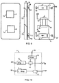
With reference to FIG. 10, there is illustrated a prior art duplex RF repeater 1. In the Duplex RF Repeater 1, the down-link RF signals communicated to the terminal 54 are amplified by the down-link amplifier 2, and then said amplified RF signals are divided into two branches by the divider 4. Divider 4 is connected by one branch to the divider 6, and the other branch of the divider 4 is connected to the terminal 56. On the other hand, the up-link RF signals communicated to the terminal 57 are combined by the divider 5 with the RF signals communicated from the divider 6, and then amplified by the up-link amplifier 3 and then communicated to the terminal 55. At the terminal 10 of the divider 6, a downstream antenna can be connected to serve subscriber units within the serving area. This scheme is not always cost effective because the downstream antenna must be connected separately through a coaxial cable, and as a result, the dimensions of the duplex RF repeater are of large size.
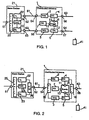
With reference to FIG. 1, the RF signals from the transmitter 22 of the base station 21 are communicated to the terminal 54 of the distributed antenna 1 through the terminal 52 and the coaxial cable 61. The receiver 23 of the base station 21 is in communication with the terminal 55 of said distributed antenna 1 through the terminal 53 and the coaxial cable 62. Said transmitter 22 and receiver 23 of the base station 21 are controlled by the controller 24, and are in communication with the telephone lines through the interface unit 25 and terminal 51. In said distributed antenna 1, the down-link amplifier 2 amplifies the down-link RF signals, and these signals are communicated to the divider 4 and then one of the divided branches of the divider 4 is in communication with the built-in common antenna element 7 through combiner 6, and these signals radiated from said antenna element 7. The other divided branch of the divider 4 is connected to the terminal 56.
Since the amplifier gain of the amplifier 2 is adjusted to match the total loss of the coaxial cable 61 and divider 4 and combiner 6, not only the radiated power from said antenna element 7 but also the output power from the terminal 56 to the next stage of said distributed antenna are almost the same magnitude as the power output from the transmitter 22 of the base station 21.
On the other hand, the RF signals transmitted from the subscriber unit 41 is received by said antenna element 7 first, and communicated to the up-link amplifier 3 through the terminal 13 and combiner 6 and divider 5. These amplified signals are further communicated to the receiver 23 of the base station 21 through the coaxial cable 62 and terminal 53. The other branch of the divider 5 is connected to the terminal 57 to connect to the next stage of said distributed antenna. Since the amplifier 3 compensates the losses caused by the coaxial cable 62, these signals transmitted from the subscriber unit 41 are received by the receiver 23 with high sensitivity.
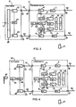
With reference to FIG. 2, the distributed antenna 1 constructed in accordance with this invention is in communication with the terminal 52 of the base station 21 through the terminal 54 and the coaxial cable 61. Said terminal 52 is further in communication with the receiver 23 and transmitter 22 of said base station 21 through the antenna switch 26. Said transmitter 22 and receiver 23 of said base station 21 are controlled by the controller 24, and in communication with the telephone lines through the interface unit 25 and terminal 51. In said distributed antenna 1, the divider 15 divides said RF signals and communicates with the down-link amplifier 2 and up-link amplifier 3. The down-link amplifier 2 amplifies the down-link RF signals, and these signals are communicated to the divider 4 and then one of the divided branches of the divider 4 is in communication with the built-in common antenna element 7 through combiner 6, and said RF signals are radiated from said antenna element 7. The other divided branch of the divider 4 is in communication with the terminal 56 through the divider 16 to connect to the coaxial cable 63. Since the amplifier gain of the amplifier 2 is adjusted to match with the total loss of the coaxial cable 61, dividers 15 and 4, and combiner 6, not only the radiated power from said antenna element 7 but also the output power from the terminal 56 to the next stage of said distributed antenna are almost the same magnitude as the power output of the transmitter 22 of the said base station 21.
On the other hand, the RF signals transmitted from the subscriber unit 41 are received by said antenna element 7 first, and communicated to the up-link amplifier 3 through the terminal 13 and combiner 6 and divider 5. These amplified signals are further communicated to the receiver 23 of said base station 21 through the divider 15, terminal 54, coaxial cable 61, terminal 52, and antenna switch 26. The other branch of the divider 5 is in communication with the terminal 56 through divider 16 to connect to the next stage of said distributed antenna. Since the amplifier 3 compensates the losses caused by the divider 15 and coaxial cable 61, said RF signals transmitted from the subscriber unit 41 are received by the receiver 23 with high sensitivity.
With reference to FIG. 3, the distributed antenna 71 constructed in accordance with this invention is in communication with the transmitter 22 of the base station 21 through a coaxial cable 61 and the terminal 52, and to the receiver 23 of the base station 21 through a coaxial cable 62 and the terminal 53. Said transmitter 22 and receiver 23 are controlled by the control unit 24 and connected to the telephone line through the telephone line interface unit 25 and the terminal 51.
Within said distributed antenna 71, the down-link RF signals are divided into two branches by the divider 4. One branch of said divider 4 is in communication with the antenna switch 77 in the combiner 6 through the terminal 11, and switched to the receiver 72. Said receiver 72 (in combination with the base band IC 75) converts said RF signals into base band signals and said transmitter 73 (in combination with the base band IC 75) modulates them into new RF signals by adapting said base band signals between said receiver 72 and said transmitter 73 in the TDMA (Time Division Multiple Access) repeater mode or CDMA (Code Division Multiple Access) repeater mode through the base band IC 75. The modulated RF signals are further communicated to the built-in antenna 7 through the built-in combiner 78 and terminal 13, and radiated toward a subscriber unit 41. RF signals from the other branch of said divider 4 are amplified by the amplifier 2 and communicated to the next stage of said distributed antenna 1 through a terminal 56 and a coaxial cable 63.
On the other hand, RF signals from a subscriber unit 41 are received by said built-in antenna 7, and communicated to the antenna switch 77 through a terminal 13 and a built-in combiner 78, and switched to the receiver 72, and then said receiver 72 (in combination with the base band IC 75) converts said RF signals into base band signals and transmitter 73 (in combination with the base band IC 75) modulates them into other new RF signals by adapting said base band signals between said receiver 72 and said transmitter 73 in the TDMA repeater mode or CDMA repeater mode through the base band IC 75. The modulated RF signals are communicated to the divider 5 through the antenna switch 79 and terminal 12, and further communicated to the receiver 23 of the base station 21 through the terminal 55, coaxial cable 62, and terminal 53. The up-link amplifier 3 amplifies the RF signals from the terminal 57, and communicates with the other branch of the divider 5.
In the above, the synthesizer 74 supplies a local RF signal to the receiver 72 and transmitter 73, the controller 76 controls the base band IC 75, transmitter 73, and antenna switches 77 and 79. By these configurations, the distance between distributed antenna can be extended tremendously.
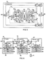
With reference to FIG. 4, the antenna coupler 81 constructed in accordance with this invention is in communication with the external base station 42 by way of the antenna 82. The down-link RF signals from said base station 42 are received by the antenna 82 and communicated to and amplified by the down-link amplifier 84, and communicated to the distributed antenna 71 at the terminal 54 through the terminal 52 and coaxial cable 61, and transmitted toward a subscriber unit 41 as described in FIG. 3 above.
On the other hand, the up-link RF signals at the terminal 55, which are transmitted from a subscriber unit 41 and amplified by said distributed antenna 1 as described above in relation to FIG. 3, are communicated to and amplified by the up-link amplifier 85 through the coaxial cable 62 and terminal 53, and said amplified up-link RF signals are communicated to said base station 42 through the combiner 86 and antenna 82.
With reference to FIG. 5, another type of distributed antenna 71 constructed in accordance with this invention includes another type of combiner 6, in which the first transceiver 91b and the second transceiver 91a are provided, and interconnected by a cascade connection. Within said distributed antenna 71, the RF signals communicated to the terminal 54 are divided by the divider 15 into the down-link RF signals and up-link RF signals. Said down-link RF signals are divided by the divider 4 into two branches, and one branch of said divider 4 is in communication with the receiver 72b in the combiner 6 through the terminal 11, and said receiver 72b converts said RF signals into the base band signals and the transmitter 73a modulates them into other RF signals by adapting said base band signals in the FDMA (Frequency Division Multiple Access) or Cascade Connection repeater mode between said receiver 72b and transmitter 73a through the base band IC 75b and 75a. Said modulated RF signals are further communicated to the built-in antenna 7 through the built-in combiner 78 and terminal 13, and radiated toward a subscriber unit 41 (not shown in Fig.5). Said RF signals from the other branch of said divider 4 are amplified by the amplifier 2 and communicated to the next stage of said distributed antenna 1 through a terminal 56.
On the other hand, RF signals from a subscriber unit 41 (not shown in Fig.5) are received by said built-in antenna 7, and communicated to the receiver 72a through a terminal 13 and a built-in combiner 78, and said receiver 72a converts said RF signals into base band signals, and the transmitter 73a modulates said base band signals into other RF signals by adapting said base band signals in the FDMA or Cascade connection repeater mode between said receiver 72a and said transmitter 73b through the base band IC 75a and 75b, and communicated to one of the branches of the divider 5 through the terminal 12, and communicated toward the terminal 54. The up-link amplifier amplifies the RF signals from the terminal 54, and communicated to the other branch of the divider 5.
With reference to FIG. 6, another type of antenna coupler 81, distributed antenna 71a, and a loop-back teeter 31 constructed in accordance with this invention are depicted. Said distributed antenna 71a is in communication with said antenna coupler 81 at the terminal 54a through a coaxial cable 61, and said loop-back teeter 31 is further in communication with said distributed antenna 71a at the terminal 58 through a coaxial cable 63.
At the antenna coupler 81, a built-in antenna 82 receives the down-link RF signals transmitted from a base station, and fed to the receiver 88 through antenna switches 83 and 87. Said receiver 88 (in combination with the base band IC 91) converts said RF signals into base band signals, and said base band signals are communicated to the transmitter 89 through the base band IC 91 and controller 92, and modulated into new down-link RF signals, and transmitted towards the distributed antenna 71a through antenna switches 87 and 83, and the coaxial cable 61.
At the distributed antenna 71a, a divider 78a feeds said down-link RF signals transmitted from said antenna coupler 81 to the receiver 72a through antenna switches 79a and 77a. Said receiver 72a (in combination with the base band IC 75a) converts said RF signals into base band signals, and said base band signals are communicated to the transmitter 73a through the base band IC 75a and controller 76a, and said base band signals are modulated into new down-link RF signals, and re-transmitted towards the subscriber unit 41 through antenna switches 77a and 79a, and the built-in antenna 7a.
At the loop-back tester 31, the down-link RF signals from said antenna coupler 81 are fed to the receiver 32 through the coaxial cable 63, the attenuator 38 and the antenna switch 37 and converted into base band signals, and communicated to the base band IC 35 and controller 36. Said controller 36 is further detecting control signals included within said base band signals. If the loop-back test command is included within said base band signals, said controller 36 sends back a loop-back answering command to said transmitter 33. Said transmitter 33 sends back said command towards the base station through said antenna switch 37, attenuator 38, coaxial cable 63, and the distributed antenna 71a. If the loss of the attenuator 38 is adjusted within limits, said antenna coupler 81 and said distributed antenna 71a can be checked including gains and functions. The synthesizers 90, 74a, and 34 are generating local RF signals and feed said RF signals into transmitters 89, 73a, and 33, and receivers 88, 72a, and 32.
On the other hand, the up-link RF signals transmitted from a subscriber unit 41 are received by the built-in antenna 7a. And said up-link RF signals are fed to the receiver 72a through antenna switches 79a and 77a, and converted into the base band signals, and communicated to the transmitter 73a through said base band IC 75a and controller 76a. Said transmitter 73a (in combination with the base band IC 75a) modulates said base band signals into new up-link RF signals and re-transmits said RF signals towards said antenna coupler 81 through antenna switches 77a and 79a, said divider 78a, and said coaxial cable 61. The receiver 88 of said antenna coupler 81 (in combination with the base band IC 91) converts said up-link RF signals into base band signals, and said base band signals are communicated to the transmitter 89 through the base band IC 91 and controller 92. Said transmitter 89 (in combination with the base band IC 91) modulates said base band signals into new up-link RF signals and re-transmits said RF signals towards said base station through antenna switches 87 and 83, and the built-in antenna 82.
If the coupling loss of the attenuator 38 is adjusted within limits, said antenna coupler 81 and said distributed antenna 71a can be checked including gains and functions.
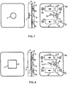
With reference to FIG. 7, a distributed antenna constructed in accordance with this invention is assembled on a single Printed Circuit Board 8, and housed within a plastic case 9. The terminals 54, 55, 56, and 57, the down-link amplifier 2 and up-link amplifier 3, the dividers 4 and 5, and the built-in combiner 6 are assembled on one side of said Printed Circuit Board 8. The built-in antenna 7 is assembled on the other side of said printed circuit board 8. Here, said combiner 6 is constructed as a circulator, and said built-in antenna is constructed with a monopole antenna 7. By the above construction, a small sized and very cheap omnidirectional distributed antenna can be realized.
With reference to FIG. 8, another type of distributed antenna 1 constructed in accordance with this invention is described, and said combiner 6 is constructed with a divider with 3dB loss, and said built-in antenna is constructed with a patch antenna with radiation element 7'. By the above constructions, a wall-mounted type directional distributed antenna can be realized.
With reference to FIG. 9, another type of distributed antenna 1 constructed in accordance with this invention is described, and said combiner 6 is constructed with a 0 degree or 180 degree hybrid coupler, and said built-in antenna 7 is constructed by two patch antennas 7a and 7b with radiation elements 7a' and 7b'. By the above constructions, a wall-mounted type directional distributed antenna can be realized. If a 0 degree hybrid coupler 6 is adopted, a single pole directional distributed antenna 1 can be realized. If a 180 degree hybrid coupler 6 is adopted, a two-pole directional distributed antenna 1 can be realized.

Claims (8)

  1. A distributed antenna (7,71,71a) for use in a digital mobile communication system, the distributed antenna comprising:
    (1) at least one RF transmission means (61,62) to communicate the RF signals received from and transmitted to a base station;
    (2) two isolated amplifier means (2,3) to amplify the respective down-link RF signals and up-link RF signals transmitted to and received from said base station;
    (3) two divider means (4,5) which divide down-link RF signals and up-link RF signals into at least two branches;
    (4) two built-in antenna means (7a,7b) which are in communication separately with one of said branches of said divider means;
    (5) at least one RF transmission means (63,64) to communicate another divided branch of said divider means with the next stage of said distributed antenna;
    (6) a printed circuit board (8) on which said built-in antenna and other electronic circuits are assembled; and
    (7) a plastic case (9) and a partially shielding case to cover said Printed Circuit Board.
  2. A distributed antenna (7,71,71a) for use in a digital mobile communication system, the distributed antenna comprising:
    (1) at least one RF transmission means (61,62) to communicate the RF signals received from and transmitted to a base station;
    (2) two isolated amplifier means (2,3) to amplify the respective down-link RF signals and up-link RF signals transmitted to and received from said base station;
    (3) two divider means (4,5) which divide down-link RF signals and up-link RF signals into at least two branches;
    (4) one common built-in antenna means (7) and combiner means (6) which are in communication with one of the branches of said divider means;
    (5) at least one RF transmission means (63,64) to communicate another divided branch of said divider means with the next stage of said distributed antenna;
    (6) a printed circuit board (8) on which said built-in antenna and other electronic circuits are assembled; and
    (7) a plastic case (9) and a partially shielding case to cover said Printed Circuit Board.
  3. A distributed antenna (7,71,71a) for use in a digital mobile communication system, the distributed antenna comprising:
    (1) at least one RF transmission means (61,62) to communicate the RF signals received from and transmitted to a base station;
    (2) combiner means (6), including at least one set of transmitter (73) and receiver (72), to convert said RF signals into base band signals and to modulate said base band signals into new RF signals by adapting said base band signals between said receiver and said transmitter to pass the RF signals to and from a divider means;
    (3) antenna means (7) which is in communication with said combiner means; and
    (4) at least one RF transmission means (63,64) to communicate another divided branch of said divider means with the next stage of said distributed antenna.
  4. A distributed antenna as claimed in claim 3, wherein said distributed antenna comprises:
    (1) two isolated amplifier means (2,3) to amplify the respective down-link RF signals and up-link RF signals transmitted to and from a base station;
    (2) a printed circuit board (8) on which said built-in antenna means and other electronic circuits are assembled; and
    (3) a plastic case (9) and a partially shielding case to cover said printed circuit board.
  5. An antenna coupler (81) to communicate said distributed antenna as claimed in claim 1, 2, or 3 with an external base station, wherein said antenna coupler comprises:
    (1) antenna means (82) to transmit and receive said RF signals to and from said base station;
    (2) two isolated amplifiers (84,85) to amplify said down-link and up-link RF signals; and
    (3) at least one RF transmission means (61,62) to communicate with said distributed antenna.
  6. An antenna coupler (81) to communicate said distributed antenna as claimed in claim 1, 2, or 3 with an external base station (42), wherein said antenna coupler comprises:
    (1) antenna means (82) to transmit and receive said RF signals to and from said base station;
    (2) combiner (86) and amplifier means (84,85), including at least one set of transmitter (89) and receiver (88), to convert said RF signals into base band signals and to modulate said base band signals into new RF signals by adapting said base band signals between said receiver and said transmitter to pass the RF signals to and from a divider means;
    (3) at least one RF transmission means (61) to communicate with said distributed antenna.
  7. A distributed antenna as claimed in claim 1, 2, or 3, wherein said distributed antenna includes frequency converting means (74,75) in between the carrier frequency band of said RF signals transmitted to and received from said base station and the carrier frequency band of said RF signals transmitted to and received from said subscriber units (41).
  8. A loop-back tester (31) to test said distributed antenna (71a) as claimed in claim 1, 2, or 3, wherein said loop-back tester comprises;
    (1) at least one RF transmission cable (63) to communicate with said distributed antenna; and
    (2) at least one set of transmitter (33) and receiver (32) to detect a loop-back test command and to transmit a loop-back answering command.
EP98201966A 1997-06-12 1998-06-12 Distributed antenna for personal communication system Withdrawn EP0884863A3 (en)

Applications Claiming Priority (15)

Application Number Priority Date Filing Date Title
JP19175597 1997-06-12
JP191755/97 1997-06-12
JP19175597 1997-06-12
JP21890097 1997-07-08
JP218900/97 1997-07-08
JP36304197 1997-11-25
JP363041/97 1997-11-25
JP36304197 1997-11-25
JP8788398 1998-02-25
JP87883/98 1998-02-25
JP8788398 1998-02-25
JP106889/98 1998-03-14
JP10688998 1998-03-14

Publications (2)

Publication Number Publication Date
EP0884863A2 true EP0884863A2 (en) 1998-12-16
EP0884863A3 EP0884863A3 (en) 2000-07-19

Family

ID=27525309

Family Applications (1)

Application Number Title Priority Date Filing Date
EP98201966A Withdrawn EP0884863A3 (en) 1997-06-12 1998-06-12 Distributed antenna for personal communication system

Country Status (3)

Country Link
US (1) US6381473B1 (en)
EP (1) EP0884863A3 (en)
CA (1) CA2240224A1 (en)

Cited By (5)

* Cited by examiner, † Cited by third party
Publication number Priority date Publication date Assignee Title
WO2000076095A1 (en) * 1999-06-03 2000-12-14 Nokia Corporation Testing of radio transceiver
FR2794655A1 (en) * 1999-04-30 2000-12-15 Medtronic Inc TELEMETRY SYSTEM FOR IMPLANTABLE MEDICAL DEVICES
WO2002062090A2 (en) * 2001-02-01 2002-08-08 Qualcomm Incorporated Dynamic capacity allocation of in-building system
GB2476085A (en) * 2009-12-10 2011-06-15 Thales Holdings Uk Plc Line transmission repeater with equalizer, suitable for use in wireless communication system for tunnel
US8515339B2 (en) 2001-05-10 2013-08-20 Qualcomm Incorporated Method and an apparatus for installing a communication system using active combiner/splitters

Families Citing this family (12)

* Cited by examiner, † Cited by third party
Publication number Priority date Publication date Assignee Title
US6831902B1 (en) * 1999-09-08 2004-12-14 Qwest Communications International, Inc. Routing information packets in a distributed network
US6816706B1 (en) 1999-09-08 2004-11-09 Qwest Communications International, Inc. Wireless communication access point
US8005077B1 (en) 1999-09-08 2011-08-23 Qwest Communications International Inc. Distributively routed VDSL and high-speed information packets
US6987769B1 (en) 1999-09-08 2006-01-17 Qwest Communications International Inc. System and method for dynamic distributed communication
US7388846B1 (en) 1999-09-08 2008-06-17 Qwest Communications International Inc. Cellularized packetized voice and data
US7283844B2 (en) * 2000-04-04 2007-10-16 Thompson Scott D Multi-beam antenna wireless network system
US7065384B2 (en) * 2001-08-21 2006-06-20 Hrl Laboratories, Llc Networked and field addressable distributed antenna system
US6965756B2 (en) * 2001-10-05 2005-11-15 Adtran, Inc. RF loopback test apparatus for data radio transceiver
US7555261B2 (en) * 2003-03-04 2009-06-30 O'neill Frank P Repeater system for strong signal environments
US6993287B2 (en) * 2003-03-04 2006-01-31 Four Bars Clarity, Llc Repeater system for strong signal environments
US7639994B2 (en) * 2006-07-29 2009-12-29 Powercast Corporation RF power transmission network and method
US10270152B2 (en) 2010-03-31 2019-04-23 Commscope Technologies Llc Broadband transceiver and distributed antenna system utilizing same

Citations (4)

* Cited by examiner, † Cited by third party
Publication number Priority date Publication date Assignee Title
EP0522538A2 (en) * 1991-07-11 1993-01-13 Nec Corporation Portable radio communication apparatus unnecessitating shielding case
EP0605182A2 (en) * 1992-12-30 1994-07-06 Yoshiro Niki Bidirectional repeater for mobile telephone system
FR2710195A1 (en) * 1993-09-14 1995-03-24 Thomson Csf Antenna-electronic circuit assembly
GB2301712A (en) * 1995-06-02 1996-12-11 Dsc Communications Integrated directional antenna

Family Cites Families (4)

* Cited by examiner, † Cited by third party
Publication number Priority date Publication date Assignee Title
US4455682A (en) * 1982-04-05 1984-06-19 Imperial Clevite Inc. Superregenerative radio receiver
JPS60116237A (en) * 1983-11-29 1985-06-22 Fujitsu Ltd Automatic response device of subscriber line
US5918154A (en) * 1995-08-23 1999-06-29 Pcs Wireless, Inc. Communications systems employing antenna diversity
US5847682A (en) * 1996-09-16 1998-12-08 Ke; Shyh-Yeong Top loaded triangular printed antenna

Patent Citations (4)

* Cited by examiner, † Cited by third party
Publication number Priority date Publication date Assignee Title
EP0522538A2 (en) * 1991-07-11 1993-01-13 Nec Corporation Portable radio communication apparatus unnecessitating shielding case
EP0605182A2 (en) * 1992-12-30 1994-07-06 Yoshiro Niki Bidirectional repeater for mobile telephone system
FR2710195A1 (en) * 1993-09-14 1995-03-24 Thomson Csf Antenna-electronic circuit assembly
GB2301712A (en) * 1995-06-02 1996-12-11 Dsc Communications Integrated directional antenna

Cited By (8)

* Cited by examiner, † Cited by third party
Publication number Priority date Publication date Assignee Title
FR2794655A1 (en) * 1999-04-30 2000-12-15 Medtronic Inc TELEMETRY SYSTEM FOR IMPLANTABLE MEDICAL DEVICES
WO2000076095A1 (en) * 1999-06-03 2000-12-14 Nokia Corporation Testing of radio transceiver
US7062235B2 (en) 1999-06-03 2006-06-13 Nokia Corporation Testing of a radio transceiver
WO2002062090A2 (en) * 2001-02-01 2002-08-08 Qualcomm Incorporated Dynamic capacity allocation of in-building system
WO2002062090A3 (en) * 2001-02-01 2003-11-06 Qualcomm Inc Dynamic capacity allocation of in-building system
US7085530B2 (en) 2001-02-01 2006-08-01 Qualcomm, Incorporated Dynamic capacity allocation of in-building system
US8515339B2 (en) 2001-05-10 2013-08-20 Qualcomm Incorporated Method and an apparatus for installing a communication system using active combiner/splitters
GB2476085A (en) * 2009-12-10 2011-06-15 Thales Holdings Uk Plc Line transmission repeater with equalizer, suitable for use in wireless communication system for tunnel

Also Published As

Publication number Publication date
CA2240224A1 (en) 1998-12-12
US6381473B1 (en) 2002-04-30
EP0884863A3 (en) 2000-07-19

Similar Documents

Publication Publication Date Title
US5812933A (en) Duplex RF repeater for personal communications system
US6381473B1 (en) Distributed antenna for personal communication system
US4704733A (en) Cell enhancer for cellular radio telephone system having diversity function
KR100216349B1 (en) Repeater of cdma system
US6069721A (en) Radio frequency control circuit of base station of mobile communications systems
US6029048A (en) Repeater system having reduced power loss
JP4753459B2 (en) Side-to-side repeater and operation method thereof
US5515365A (en) Method and apparatus for reducing interference in a time division duplex communication system
JPH0744495B2 (en) Compartmental wireless telephone performance improvement circuit
US20010038670A1 (en) Multibit spread spectrum signalling
US20070010198A1 (en) Method and apparatus for utilizing selective signal polarization and interference cancellation for wireless communication
KR100375143B1 (en) Modular and distributed radio unit architecture and dual carrier connection apparatus using same antennas
EP0937366B1 (en) Method of combining several signals, and base station
JPH07297783A (en) Radio communication system
EP1081878A2 (en) Single antenna repeater and method of repeating a signal
KR100321481B1 (en) Image FA hopping generator using RF coupling method for CDMA cellular system
JP2972699B2 (en) Radio base station and antenna unit
JPH07235898A (en) Base station distribution equipment
KR100285963B1 (en) Base station for covering shadow area
AU726323B2 (en) Transmitter unit and base station
JPH0879151A (en) Base station distribution device
JP2868659B2 (en) Relay system for mobile communication
JP3018499U (en) Transmission distributed antenna
KR20030068334A (en) A Outer RF Repeater System
KR20030021970A (en) Method and device that radio communication network in the cloud buster

Legal Events

Date Code Title Description
PUAI Public reference made under article 153(3) epc to a published international application that has entered the european phase

Free format text: ORIGINAL CODE: 0009012

17P Request for examination filed

Effective date: 19980702

AK Designated contracting states

Kind code of ref document: A2

Designated state(s): AT BE CH CY DE DK ES FI FR GB GR IE IT LI LU MC NL PT SE

AX Request for extension of the european patent

Free format text: AL;LT;LV;MK;RO;SI

PUAL Search report despatched

Free format text: ORIGINAL CODE: 0009013

AK Designated contracting states

Kind code of ref document: A3

Designated state(s): AT BE CH CY DE DK ES FI FR GB GR IE IT LI LU MC NL PT SE

AX Request for extension of the european patent

Free format text: AL;LT;LV;MK;RO;SI

STAA Information on the status of an ep patent application or granted ep patent

Free format text: STATUS: THE APPLICATION HAS BEEN WITHDRAWN

18W Application withdrawn

Withdrawal date: 20001107