EP0884611A2 - Precision wavelength control for automated fiber optic bragg grating writing - Google Patents
Precision wavelength control for automated fiber optic bragg grating writing Download PDFInfo
- Publication number
- EP0884611A2 EP0884611A2 EP98107563A EP98107563A EP0884611A2 EP 0884611 A2 EP0884611 A2 EP 0884611A2 EP 98107563 A EP98107563 A EP 98107563A EP 98107563 A EP98107563 A EP 98107563A EP 0884611 A2 EP0884611 A2 EP 0884611A2
- Authority
- EP
- European Patent Office
- Prior art keywords
- mirror
- fiber
- laser
- bragg
- wavelength
- Prior art date
- Legal status (The legal status is an assumption and is not a legal conclusion. Google has not performed a legal analysis and makes no representation as to the accuracy of the status listed.)
- Withdrawn
Links
Images


Classifications
-
- G—PHYSICS
- G02—OPTICS
- G02B—OPTICAL ELEMENTS, SYSTEMS OR APPARATUS
- G02B6/00—Light guides; Structural details of arrangements comprising light guides and other optical elements, e.g. couplings
- G02B6/02—Optical fibres with cladding with or without a coating
- G02B6/02057—Optical fibres with cladding with or without a coating comprising gratings
- G02B6/02076—Refractive index modulation gratings, e.g. Bragg gratings
- G02B6/02123—Refractive index modulation gratings, e.g. Bragg gratings characterised by the method of manufacture of the grating
- G02B6/02133—Refractive index modulation gratings, e.g. Bragg gratings characterised by the method of manufacture of the grating using beam interference
Definitions
- the present invention generally relates to Bragg gratings and, more particularly, to an apparatus and method for producing high quality fiber optic Bragg gratings with precise control of the Bragg center wavelength.
- Most fiber optic Bragg gratings are manufactured by exposing the core of a fiber to an intense, spatially modulated ultra violet (UV) beam of radiation.
- UV light induces an increase in the index of refraction of the core material in the fiber optic.
- ⁇ B 2n ⁇ , where n is the mean index of refraction in the fiber core.
- the apparatus includes a laser for generating an ultraviolet beam, a rotatable scrapper mirror disposed downstream of the laser for receiving the beam and an optical fiber disposed perpendicular to an edge of the scrapper mirror for receiving a high fringe frequency interferrogram formed by the scrapper mirror.
- the mirror is coupled to a rotation stage for rotating the minor about a pre-selected pivot point relative to the angle of incidence of the beam to vary the Bragg wavelength at the fiber core.
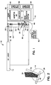
- FIG. 1 illustrates an apparatus for producing fiber optic Bragg gratings in accordance with the present invention generally at 10.
- the apparatus 10 generally includes a laser 12, rotation stage 14, and a controller 16.
- the laser 12 is preferably a commercially available continuous wave (CW) laser suitable for generating an ultraviolet beam 18. Even more preferably, the laser 12 is an Argon ion laser including a Beta-Barium Borate (BBO) crystal within the laser cavity providing frequency doubled output. For instance, the laser 12 may produce a 100mW CW beam 18 having a 244nm wavelength with long coherence length and high beam quality. A tube 19 is used to enclose the beam 18 to prevent open air current from causing wave front distortion.
- CW continuous wave
- BBO Beta-Barium Borate
- a half waveplate 20 optically communicates with the laser 12 for rotating the polarization of the beam 18 by 90°. Rotating the polarity of the beam 18 is necessary to form the correct high frequency fringe pattern described below.
- a galilean telescope 22 is disposed downstream of the waveplate 20 for receiving the beam 18.
- the galilean telescope 22 includes a negative lens 24 for beam expansion, an aperture 26 to isolate the central beam from the laser 12 and a positive lens 28 to collimate the beam to the desired diameter.
- a 1.6cm diameter beam is used herein.
- a cylindrical lens 30 is disposed in light receiving relation to the galilean telescope 22 for forming a line focus from the beam 18.
- a cylindrical lens including a 15cm focal length has been found particularly well suited for this purpose.
- a scrapper mirror 32 is coupled to the rotation stage 14 such that it receives the line focus from the cylindrical lens 30.
- the scrapper mirror is a 3 inch-type mirror having a 100% reflectivity coating thereon optimized for polarization in the S direction.
- the rotation stage 14 communicates with a nano-controller 34 of the controller 16 for precisely rotating the mirror 32 relative to the incident angle of the beam 18. By rotating the mirror 32, the Bragg wavelength may be varied.
- a plastic enclosure 35 houses the optical train for minimizing wave front distortion.
- a pivot point 36 about which the mirror 32 rotates ensures proper alignment of the line focus with the fiber core when the mirror 32 is rotated to change the grating spacing.
- automated manufacturing of fiber optic Bragg gratings is enhanced by appropriately selecting the pivot point 36: Through proper selection, the pivot point 36 alleviates the need for translating the mirror 32 when changing to a new Bragg wavelength.
- the nano-controller 34 includes a computer or central processing unit (CPU) 38, monitor 40, and keyboard 42.
- the CPU 38 also communicates with a beam diagnostic system 44 including a dedicated keyboard 46.
- the nano-controller 34 supplies the drive signal for adjusting the angle of the mirror 32. This adjusting is controlled by the CPU 38.
- An optical fiber 48 is secured adjacent the mirror 32 by a fiber mount 50. As best seen in FIGS. 3a-3c, the fiber 48 is held under tension on a three axis translation stage 52 which preferably has one micron adjustment resolution. This level of adjustment is preferable since the core diameter of the fiber 48 may be as small as 2 to 5 microns.
- a final translation stage 54 moves one end 56 of the fiber 48 up and down to assure that the line foci from the two paths of the incident beam (one direct and one reflected from the mirror 32) coincide with the fiber core. Final alignment is provided by adjusting the single slit diffraction patterns created by the two line foci diffracting off the fiber core.
- the tension applied to the fiber 48 is set by monitoring the value displayed on a gauge 58 mounted to the fiber mount 50. A shift in wavelength is realized for the specific tension applied to the fiber 48. This known amount is taken into account when mailing the wavelength positioning setting.
- the nano-controller 34 supplies the drive signal to the nano-drive 100 which moves the moment arm 102 of the rotation drive 104 to adjust the angle of the mirror 32.
- the nano-drive 100 is controlled by the CPU 38 which steps the nano-drive 100 to provide micro-radian angular intervals.
- the specific angle of the mirror 32 is to set to the angle required for the Bragg wavelength desired as described below.
- the fiber optic 48 extends between a light emitting diode (LED) 60 and an optical spectrum analyzer 62.
- LED light emitting diode
- the transmission spectrum may be monitored on the analyzer 62 while the grating is being formed to verify the wavelength and reflectivity of the Bragg grating. As such, any desired reflectivity can be achieved.
- the mirror 32 is illustrated in a first position appropriate for writing Bragg gratings at a preselected wavelength.
- this wavelength may be of particular interest for the communications industry.
- the present invention is also suitable for writing Bragg gratings within other wavelength ranges.
- the first, second or preselected wavelengths described within this specification represent regions of wavelengths and therefore is not limited to any specific wavelength stated.
- the mirror 32 may be moved to new Bragg wavelength positions by rotating the mirror 32 about a preselected pivot point 36. However, if the pivot point 36 is incorrectly selected, the mirror 32 must also be translated to maintain optimum alignment.
- the mirror 32 is in the proper position for writing a Bragg grating at a known wavelength.
- the UV writing beam center axis 72 is incident upon the face 74 of the mirror 32.
- the left portion 78 of the beam 18 reflects off the face 74 of the mirror 32 while the right portion 82 of the beam 18 travels directly to the fiber 48.
- the left portion 78 of the beam 18 overlaps the right portion 82 of the beam 18 creating the high-fringe frequency interferrogram 86 required for writing the Bragg grating.
- the beam overlap is not symmetric. That is, the left portion 78 or right portion 82 of the beam 18 does not have the same spatial extent as the other half 82, 78 of the beam 18.
- a symmetric overlap is assured by rotating the mirror 32 about the optimum pivot point 36 to change the Bragg wavelength.
- a translation of the mirror 32 may be required to achieve a symmetric overlap of the left portion 78 and right portion 82 of the UV writing beam 18 if the rotation is performed about an incorrect pivot point 36.
- the mirror 32 may be rotated about the pivot point 36 for selective positioning the mirror 32 to one of a range of known wavelength Bragg writing locations.
- the axial position along the UV beam 18 is chosen such that the cylindrical focus of the beam 18 contacts the core of the fiber 48 (FIG. 1).
- the cylindrical lens 30 in order to assure proper alignment of the line focus with the fiber 48, it may be necessary to rotate the cylindrical lens 30 relative to the beam 18. To accomplish this, the cylindrical lens 30 is rotated to be parallel to the fiber 48 to cause the line focus to be perpendicular to the fiber 48. This assures properly matched interference at the fiber 48 which produces the high spatial frequency interferrogram 86 at the core of the fiber 48 and forms the spatially modulated UV light necessary for creating the fiber optic Bragg grating.
- the pivot point 36 for the mirror 32 remains valid when changing from one wavelength region to another, for example, 1300nm to 1500nm.
- the location of the pivot point 36 is valid for a broad range of incident angles. Accordingly, high quality Bragg gratings may be routinely manufactured with precise control of the Bragg center wavelength. Furthermore, the tedious realignment of the apparatus elements as required in prior art systems for writing at different wavelengths is alleviated.
Landscapes
- Physics & Mathematics (AREA)
- Engineering & Computer Science (AREA)
- Manufacturing & Machinery (AREA)
- General Physics & Mathematics (AREA)
- Optics & Photonics (AREA)
- Optical Fibers, Optical Fiber Cores, And Optical Fiber Bundles (AREA)
- Diffracting Gratings Or Hologram Optical Elements (AREA)
Abstract
Description
Claims (20)
- An apparatus for writing fiber optic Bragg gratings over a range of Bragg wavelengths, said apparatus comprising:a laser for generating an ultraviolet beam;a mirror disposed downstream of said laser such that said beam is incident on a face of said mirror;a cylindrical lens interposed between said laser and said mirror for aligning a line focus of said beam parallel with said face of said mirror;a rotation stage coupled to said mirror for rotating said mirror about a pre-selected pivot point relative to an angle of incidence of said beam to vary said Bragg wavelength within said range; andan optical fiber disposed adjacent an edge of said mirror for receiving a high fringe frequency interferrogram formed by said mirror from said beam on a core portion thereof, said high fringe frequency interferrogram writing said Bragg grating thereon.
- The apparatus of Claim 1 wherein said mirror further comprises a scrapper mirror.
- The apparatus of Claim 1 further comprising:a fiber mount for securing said fiber adjacent said edge of said mirror, said fiber mount including a three axis translation stage for adjusting a position of said core relative to said line focus.
- The apparatus of Claim 1 further comprising:a half waveplate interposed between said laser and said cylindrical lens for rotating a polarization of said beam by 90°.
- The apparatus of Claim 1 further comprising:a galilean telescope interposed between said laser and said cylindrical lens for changing a diameter of said beam to a predetermined size.
- The apparatus of Claim 1 further comprising:an optical spectrum analyzer coupled to a first end of said optical fiber for monitoring a wavelength and reflectively of said core while said Bragg grating is being formed.
- The apparatus of Claim 1 further comprising:a nano-controller operably coupled to said rotation stage for precisely rotating said mirror relative to said beam.
- The apparatus of Claim 1 wherein said pivot point is located at a position about which said mirror may be rotated between a first orientation for writing Bragg gratings at a first wavelength and a second orientation for writing Bragg gratings at a second wavelength.
- The apparatus of Claim 1 wherein said laser further comprises an Argon ion laser including a Beta-Barium Borate crystal for providing frequency doubled output.
- The apparatus of Claim 1 wherein said beam further comprises a 100mW continuous wave beam at a 244nm wavelength.
- The apparatus of Claim 1 wherein said mirror further comprises a three inch type scrapper mirror having a 100% reflectivity coating deposited thereon polarized in the S-direction.
- The apparatus of Claim 1 wherein said cylindrical lens further comprises a cylindrical lens having 15cm focal length.
- The apparatus of Claim 3 wherein said fiber mount further comprises a final translation stage for moving one end of said fiber vertically with respect to said mirror to align said line focus with said core of said fiber.
- The apparatus of Claim 3 wherein said fiber mount further comprises a tensioning member for shifting said Bragg wavelength according to a tension applied to said fiber.
- The apparatus of Claim 5 wherein said galilean telescope further comprises:a beam spreader for expanding a diameter of said beam; anda collimating lens for maintaining said beam at a preselected diameter.
- The apparatus of Claim 15 wherein said preselected diameter is equal to 1.6cm.
- The apparatus of Claim 7 wherein said nano-controller further comprises a computer operably coupled to a beam diagnostic system.
- A method of writing fiber optic Bragg gratings over a range of Bragg wavelengths comprising the steps of:selecting a laser for generating an ultraviolet beam;positioning a mirror downstream of said laser such that said beam is incident on a face of said mirror;interposing a cylindrical lens between said laser and said mirror for aligning a line focus of said beam parallel with said face of said mirror;coupling a rotation stage to said mirror for rotating said mirror about a pre-selected pivot point relative to an angle of incidence of said beam to vary said Bragg wavelength within said range;securing an optical fiber adjacent an edge of said mirror for receiving a high fringe frequency interferrogram formed by said mirror from said beam on a core portion thereof, said high fringe frequency interferrogram writing said Bragg grating thereon; andcausing said line focus to impinge on said core portion of said fiber.
- The method of Claim 18 further comprising:providing a fiber mount for securing said fiber adjacent said edge of said mirror, said fiber mount including a three axis translation stage for adjusting a position of said core relative to said line focus.
- The method of Claim 18 wherein said mirror further comprises a scrapper mirror.
Applications Claiming Priority (2)
| Application Number | Priority Date | Filing Date | Title |
|---|---|---|---|
| US08/868,827 US5898804A (en) | 1997-06-09 | 1997-06-09 | Precision wavelength control for automated fiber optic Bragg grating writing |
| US868827 | 1997-06-09 |
Publications (2)
| Publication Number | Publication Date |
|---|---|
| EP0884611A2 true EP0884611A2 (en) | 1998-12-16 |
| EP0884611A3 EP0884611A3 (en) | 1999-04-28 |
Family
ID=25352393
Family Applications (1)
| Application Number | Title | Priority Date | Filing Date |
|---|---|---|---|
| EP98107563A Withdrawn EP0884611A3 (en) | 1997-06-09 | 1998-04-24 | Precision wavelength control for automated fiber optic bragg grating writing |
Country Status (5)
| Country | Link |
|---|---|
| US (1) | US5898804A (en) |
| EP (1) | EP0884611A3 (en) |
| JP (1) | JP3330874B2 (en) |
| KR (1) | KR19990006475A (en) |
| TW (1) | TW367420B (en) |
Cited By (2)
| Publication number | Priority date | Publication date | Assignee | Title |
|---|---|---|---|---|
| EP0884612A2 (en) * | 1997-06-09 | 1998-12-16 | TRW Inc. | Method of and apparatus for the automated precision wavelength control of fiber optic bragg grating writing |
| FR2813398A1 (en) * | 2000-08-30 | 2002-03-01 | France Telecom | PROCESS FOR THE FEEDING OF A BRAGG NETWORK |
Families Citing this family (15)
| Publication number | Priority date | Publication date | Assignee | Title |
|---|---|---|---|---|
| FR2764394B1 (en) * | 1997-06-10 | 1999-08-06 | France Telecom | PHOTO REGISTRATION BENCH FOR BRAGG NETWORKS |
| KR100322121B1 (en) | 1998-10-13 | 2002-03-08 | 윤종용 | Apparatus for fabricating long-period grating filter |
| US6084998A (en) * | 1998-12-30 | 2000-07-04 | Alpha And Omega Imaging, Llc | System and method for fabricating distributed Bragg reflectors with preferred properties |
| KR100374039B1 (en) * | 2000-04-01 | 2003-02-26 | 오철한 | Method of manufacturing of wave optics experimental slit |
| US6795600B1 (en) | 2001-07-26 | 2004-09-21 | Lightwave Microsystems Corporation | Waveplate for optical integrated circuits and methods for manufacturing the same |
| US6807339B1 (en) | 2001-09-14 | 2004-10-19 | Fibera, Inc. | Wavelength division multiplexing and de-multiplexing system |
| US6748138B2 (en) * | 2001-09-14 | 2004-06-08 | Fibera, Inc. | Optical grating fabrication |
| US6904200B2 (en) | 2001-09-14 | 2005-06-07 | Fibera, Inc. | Multidimensional optical gratings |
| US6718092B2 (en) | 2001-09-14 | 2004-04-06 | Fibera, Inc. | Frequency detection, tuning and stabilization system |
| US7194162B2 (en) | 2002-02-22 | 2007-03-20 | Neophotonics Corporation | Filter response optimization for an arrayed waveguide grating device by adjusting grating optical path length at nanometer scale |
| KR20030086040A (en) * | 2002-05-03 | 2003-11-07 | 주식회사 한광 | Device for setting the beam diameter of laser beam machine |
| US20050280887A1 (en) * | 2004-06-02 | 2005-12-22 | Betin Alexander A | Outcoupler with bragg grating and system and method using same |
| GB2427910B (en) * | 2005-07-02 | 2008-03-12 | Sensor Highway Ltd | Fiber optic temperature and pressure sensor and system incorporating same |
| CN102362204B (en) * | 2009-01-21 | 2014-01-15 | 印度信息技术部秘书处 | A process and system for manufacturing stable fiber bragg gratings (FBGS) |
| US9417103B2 (en) | 2011-09-20 | 2016-08-16 | Schlumberger Technology Corporation | Multiple spectrum channel, multiple sensor fiber optic monitoring system |
Citations (5)
| Publication number | Priority date | Publication date | Assignee | Title |
|---|---|---|---|---|
| US5218651A (en) * | 1991-03-25 | 1993-06-08 | Gaz De France | Optical fibre incorporating a variable internal bragg grating and its applications |
| US5377288A (en) * | 1990-04-06 | 1994-12-27 | British Telecommunications Public Limited Company | Method of forming a refractive index grating in an optical waveguide |
| US5400422A (en) * | 1993-01-21 | 1995-03-21 | The United States Of America As Represented By The Secretary Of The Navy | Technique to prepare high-reflectance optical fiber bragg gratings with single exposure in-line or fiber draw tower |
| US5629998A (en) * | 1996-01-29 | 1997-05-13 | Corning Incorporated | Method and apparatus for writing photosensitive grating using Lloyd's mirror |
| US5708738A (en) * | 1996-03-05 | 1998-01-13 | The United States Of America As Represented By The Secretary Of The Navy | Apparatus and process for making fiber optic bragg gratings |
Family Cites Families (2)
| Publication number | Priority date | Publication date | Assignee | Title |
|---|---|---|---|---|
| AU666382B2 (en) * | 1992-05-01 | 1996-02-08 | Nippon Telegraph & Telephone Corporation | Method for identifying optical line |
| US5745617A (en) * | 1996-12-30 | 1998-04-28 | D-Star Technologies, Llc | Near-ultra-violet formation of refractive-index grating using reflective phase mask |
-
1997
- 1997-06-09 US US08/868,827 patent/US5898804A/en not_active Expired - Lifetime
-
1998
- 1998-04-21 TW TW087106085A patent/TW367420B/en active
- 1998-04-24 EP EP98107563A patent/EP0884611A3/en not_active Withdrawn
- 1998-05-20 KR KR1019980018129A patent/KR19990006475A/en not_active Application Discontinuation
- 1998-06-04 JP JP15596998A patent/JP3330874B2/en not_active Expired - Fee Related
Patent Citations (5)
| Publication number | Priority date | Publication date | Assignee | Title |
|---|---|---|---|---|
| US5377288A (en) * | 1990-04-06 | 1994-12-27 | British Telecommunications Public Limited Company | Method of forming a refractive index grating in an optical waveguide |
| US5218651A (en) * | 1991-03-25 | 1993-06-08 | Gaz De France | Optical fibre incorporating a variable internal bragg grating and its applications |
| US5400422A (en) * | 1993-01-21 | 1995-03-21 | The United States Of America As Represented By The Secretary Of The Navy | Technique to prepare high-reflectance optical fiber bragg gratings with single exposure in-line or fiber draw tower |
| US5629998A (en) * | 1996-01-29 | 1997-05-13 | Corning Incorporated | Method and apparatus for writing photosensitive grating using Lloyd's mirror |
| US5708738A (en) * | 1996-03-05 | 1998-01-13 | The United States Of America As Represented By The Secretary Of The Navy | Apparatus and process for making fiber optic bragg gratings |
Non-Patent Citations (1)
| Title |
|---|
| XU MAI ET AL: "Simple versatile method for fabricating guided-wave gratings (interferometric technique)" APPLIED OPTICS, 1 OCT. 1985, USA, vol. 24, no. 19, pages 3155-3161, XP002094858 ISSN 0003-6935 * |
Cited By (6)
| Publication number | Priority date | Publication date | Assignee | Title |
|---|---|---|---|---|
| EP0884612A2 (en) * | 1997-06-09 | 1998-12-16 | TRW Inc. | Method of and apparatus for the automated precision wavelength control of fiber optic bragg grating writing |
| EP0884612A3 (en) * | 1997-06-09 | 2001-01-24 | TRW Inc. | Method of and apparatus for the automated precision wavelength control of fiber optic bragg grating writing |
| FR2813398A1 (en) * | 2000-08-30 | 2002-03-01 | France Telecom | PROCESS FOR THE FEEDING OF A BRAGG NETWORK |
| WO2002018996A2 (en) * | 2000-08-30 | 2002-03-07 | France Telecom | Apodization method for a bragg grating |
| WO2002018996A3 (en) * | 2000-08-30 | 2002-07-18 | France Telecom | Apodization method for a bragg grating |
| US6868208B2 (en) | 2000-08-30 | 2005-03-15 | France Telecom | Apodization method for a bragg grating |
Also Published As
| Publication number | Publication date |
|---|---|
| EP0884611A3 (en) | 1999-04-28 |
| JPH116925A (en) | 1999-01-12 |
| US5898804A (en) | 1999-04-27 |
| KR19990006475A (en) | 1999-01-25 |
| TW367420B (en) | 1999-08-21 |
| JP3330874B2 (en) | 2002-09-30 |
Similar Documents
| Publication | Publication Date | Title |
|---|---|---|
| US6093927A (en) | Automated precision wavelength control for fiber optic Bragg grating writing | |
| US5898804A (en) | Precision wavelength control for automated fiber optic Bragg grating writing | |
| US7324286B1 (en) | Optical beam steering and switching by optically controlled liquid crystal spatial light modulator with angular magnification by high efficiency PTR Bragg gratings | |
| US5351321A (en) | Bragg grating made in optical waveguide | |
| JP3059761B2 (en) | Method and apparatus for forming asynchronous diffraction grating of optical fiber | |
| US5655040A (en) | Method of forming a dispersing grating in an optical fiber | |
| EP0000810A1 (en) | Method of and apparatus for forming focusing diffraction gratings for integrated optics | |
| US6269208B1 (en) | Wavelength tuning of photo-induced gratings | |
| US6853772B2 (en) | Fiber grating writing interferometer with continuous wavelength tuning and chirp capability | |
| JPH1054914A (en) | Method for forming grating at optical waveguide | |
| US6606432B2 (en) | Phase mask consisting of an array of multiple diffractive elements for simultaneous accurate fabrication of large arrays of optical couplers and method for making same | |
| EP0978738A1 (en) | Apparatus and method for generating an interference pattern to be written as a grating in a sample of a photosensitive material | |
| US5708738A (en) | Apparatus and process for making fiber optic bragg gratings | |
| JPH0422442B2 (en) | ||
| US5016951A (en) | Fiber optic diffraction grating maker | |
| CN112558216A (en) | Reflection compensation type high-density multi-core fiber grating preparation system | |
| US7079729B2 (en) | Apparatus for generating an optical interference pattern | |
| US6873762B1 (en) | Fabrication of fiber optic grating apparatus and method | |
| US20040145744A1 (en) | Measuring array | |
| JP3334417B2 (en) | Method and apparatus for producing optical waveguide type diffraction grating | |
| EP3988973B1 (en) | Method and control system for controlling a process for writing gratings into an optical fiber | |
| JPH0385578A (en) | Hologram recorder | |
| JPH08286009A (en) | Device for forming chirp grating | |
| KR20020049493A (en) | Method and device to fabricate holographic gratings with large area uniformity | |
| JPH0829631A (en) | Apparatus for producing chirp grating |
Legal Events
| Date | Code | Title | Description |
|---|---|---|---|
| PUAI | Public reference made under article 153(3) epc to a published international application that has entered the european phase |
Free format text: ORIGINAL CODE: 0009012 |
|
| AK | Designated contracting states |
Kind code of ref document: A2 Designated state(s): DE FR GB IT |
|
| AX | Request for extension of the european patent |
Free format text: AL;LT;LV;MK;RO;SI |
|
| PUAL | Search report despatched |
Free format text: ORIGINAL CODE: 0009013 |
|
| AK | Designated contracting states |
Kind code of ref document: A3 Designated state(s): AT BE CH CY DE DK ES FI FR GB GR IE IT LI LU MC NL PT SE |
|
| AX | Request for extension of the european patent |
Free format text: AL;LT;LV;MK;RO;SI |
|
| 17P | Request for examination filed |
Effective date: 19990526 |
|
| AKX | Designation fees paid |
Free format text: DE FR GB IT |
|
| 17Q | First examination report despatched |
Effective date: 20010301 |
|
| GRAG | Despatch of communication of intention to grant |
Free format text: ORIGINAL CODE: EPIDOS AGRA |
|
| STAA | Information on the status of an ep patent application or granted ep patent |
Free format text: STATUS: THE APPLICATION HAS BEEN WITHDRAWN |
|
| 18W | Application withdrawn |
Withdrawal date: 20020626 |