EP0884493A1 - One-way freewheeling clutch with sprags disposed within pockets in the inner or outer race - Google Patents
One-way freewheeling clutch with sprags disposed within pockets in the inner or outer race Download PDFInfo
- Publication number
- EP0884493A1 EP0884493A1 EP98303133A EP98303133A EP0884493A1 EP 0884493 A1 EP0884493 A1 EP 0884493A1 EP 98303133 A EP98303133 A EP 98303133A EP 98303133 A EP98303133 A EP 98303133A EP 0884493 A1 EP0884493 A1 EP 0884493A1
- Authority
- EP
- European Patent Office
- Prior art keywords
- sprags
- clutch assembly
- pockets
- freewheeling
- race
- Prior art date
- Legal status (The legal status is an assumption and is not a legal conclusion. Google has not performed a legal analysis and makes no representation as to the accuracy of the status listed.)
- Withdrawn
Links
Images


Classifications
-
- F—MECHANICAL ENGINEERING; LIGHTING; HEATING; WEAPONS; BLASTING
- F16—ENGINEERING ELEMENTS AND UNITS; GENERAL MEASURES FOR PRODUCING AND MAINTAINING EFFECTIVE FUNCTIONING OF MACHINES OR INSTALLATIONS; THERMAL INSULATION IN GENERAL
- F16D—COUPLINGS FOR TRANSMITTING ROTATION; CLUTCHES; BRAKES
- F16D41/00—Freewheels or freewheel clutches
- F16D41/06—Freewheels or freewheel clutches with intermediate wedging coupling members between an inner and an outer surface
- F16D41/069—Freewheels or freewheel clutches with intermediate wedging coupling members between an inner and an outer surface the intermediate members wedging by pivoting or rocking, e.g. sprags
Definitions
- This invention relates to one-way freewheeling clutches having tiltable sprags disposed between concentric races for automatically controlling torque delivery between a driving member and a driven member.
- Conventional freewheeling sprag type clutches include inner and outer concentric races and a plurality of sprags disposed between the races.
- the prior art freewheeling spray type clutches often include a holder, sometimes referred to as a cage, for mounting the sprags.
- United States Patent Nos. 5,139,123 and 5,445,255 disclose prior art sprag type clutches which include inner and outer concentric races.
- the sprags are tiltable to engage and disengage the concentric clutch races.
- the sprags tilt to engage and lock the clutch when moving in one direction of rotation and tilt to disengage and allow overrunning or freewheeling of the clutch when moving in an opposite direction.
- Patent No. 3,515,249 does not disclose a freewheeling clutch as described above, but rather, discloses a sprag clutch having a torque sensitive releasing means.
- Patent No. 3,515,249 which is not a freewheeling clutch does disclose a releasable coupling member having sockets. Sprag elements are pivotally slideably engaged in the sockets.
- the present invention relates to an improved freewheeling one-way clutch assembly.
- the clutch assembly includes an outer race having an annular inner surface and an inner race having an annular outer surface coaxially disposed with the outer race.
- a plurality of sprags having opposed ends are spaced circumferentially at predetermined intervals between the inner surface and outer surface.
- At least one of the race surfaces defines circumferentially spaced pockets for receiving the sprag ends, whereby the sprags rotate or pivot within the pockets as the clutch is moved between a freewheel position and a locked position.
- one or two cages or holders are provided between the races and hold the sprags.
- An energizing spring is provided to ensure proper phasing of the sprags.
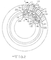
- an improved one-way freewheeling clutch assembly is generally indicated by the reference number 10.
- the clutch assembly 10 includes an outer race 11 having annular inner surface 12 and a concentric inner race 13 having an annular outer surface 14.
- the annular inner surface 12 of the outer race 11 is radially spaced from the annular outer surface 14 of the inner race 13.
- a plurality of locking elements or sprags 16 having opposed ends 17 and 18 are spaced circumferentially at predetermined intervals between the inner surface 12 and the outer surface 14.
- the sprags 16 have a narrowed center section 20 which are received in openings 21 defined in an annular energizing spring 22.
- the energizing spring 22 is a metallic flat ribbon spring.
- the annular outer surface 14 of the inner race 13 defines a plurality of circumferentially spaced pockets 24 which receive the inner ends 18 of the sprags 16.
- the one-way freewheeling clutch assembly 10, shown in Figs. 1-3, does not include either an outer or an inner cage.
- the sprags 16 have generally flat, parallel side surfaces 25 and 26.
- the ends 18 of the sprags 16 are generally arcuate and are complimentary with the arcuate shape of the pockets 24.
- the sprags 16 rotate in the pockets 24 as the sprags are moved between the normal free-wheeling position when the inner and outer races 11 and 13 rotate relative to one another and a locked position where the ends 17 of the sprags 16 are tilted and positioned against the inter surface 12 of the outer race 11 to lock the outer race 11 and the inner race 13 together.
- the pockets 24 have a shape which allows the sprags 16 to initially move slightly to position themselves properly within the pockets 24. It has been found that the pockets 24 guide the sprags 16 wherein the sprags 16 travel with the pocketed race. In the Figs. 1-3 embodiment the sprags 16 travel with the inner race 13.
- the pockets 24 with the inner race 13 are forged, cast or machined.
- the pockets 16 can be formed without a secondary grinding operation.
- ring shaped end bearings (not shown) are provided between the races 11 and 13 in a position spaced from the sprags 16 and the energizing spring 22.
- the clutch assembly 30 includes an outer race 31 having an annular inner surface 32.
- the clutch assembly 30 also includes an inner race 33 having an annular outer surface 34 which is concentric with and radially spaced from the inner surface 32 of the outer race 31.
- the outer race 31 of the clutch assembly 30 defines a plurality of circumferentially spaced pockets 36 in its inner surface 32.
- a plurality of sprags 37 having opposed ends 38 and 39 are spaced circumferentially at predetermined intervals between the inner surface 32 of the race 31 and the outer surface 34 of the race 33.
- An energizing spring 41 in this embodiment a metallic ribbon spring, defines openings 42 which receive the narrowed portions of the sprag 37.
- An annular inner cage 44 defines circumferentially spaced and axially extending slots 45 which receive and hold the ends 39 of the sprags 37.
- the opposed ends 38 of the sprags 37 are received by the pockets 36 and rotate in the pockets 36. As the outer race 31 having the packets 36 rotate, the clutch assembly 10 rotates in the direction of that race.
- a still further embodiment of a one-way freewheeling clutch assembly is generally indicated in Figs. 6 and 7 by the reference number 50.
- the clutch assembly 50 includes an outer race 51 having an annular inner surface 52.
- An inner race 53 has an annular outer surface 54 which is radially spaced from the inner surface 52 of the outer race 51.
- a plurality of locking elements or sprags 56 having opposed ends 57 and 58 are spaced circumferentially at predetermined intervals between the inner surface 52 and the outer surface 54.
- the sprags 56 serve as locking elements as the clutch assembly 50 is moved between its freewheeling position where the outer race 51 and inner race 53 rotate relative to one another and a locked position were the races 51 and 53 are locked together.
- An annular energizing spring 60 in this embodiment a ribbon spring, has openings 61 which receive a narrowed portion of the sprags 56.
- the sprags 56 have generally flat and parallel side edges as shown in Fig. 7.
- the annular outer surface 54 of the inner race 53 defines a plurality of circumferentially spaced pockets 63 having a generally arcuate cross-section.
- the pockets receive the arcuate and complementary shaped ends 58 of the sprags 56.
- the sprags 56 pivot or rotate within the pockets 63.
- an annular outer cage 65 having slots 66 is positioned in the space between the races 51 and 53. The slots 66 receive and hold the ends 57 of the sprags 56.
- a still further embodiment of a one-way freewheeling clutch assembly, according to the present invention, is generally indicated in Figs. 8 and 9 by the reference number 70.
- the clutch assembly 70 includes an annular outer race 71 having an inner surface 72.
- An inner race 73 having an annular outer surface 74 is coaxially disposed with the outer race 71.
- a plurality of locking elements or sprags 76 having opposed ends 77 and 78 are circumferentially spaced at predetermined intervals between the inner surface 72 and outer surface 74.
- An annular energizing spring 80 having openings 81 is positioned between the races 71 and 73. The openings 81 receive narrowed portions of the sprags 76.
- the inner surface 72 of the outer race 71 defines a plurality of spaced pockets 83 having a generally arcuate cross-sections.
- the pockets 83 receive complementary arcuate ends 77 of the sprags 76.
- the sprags 76 rotate within the pockets 83 as the clutch assembly 70 is moved between its freewheel position and its locked position.
Abstract
A freewheeling one-way clutch assembly (10) is disclosed. The clutch
assembly includes an annular outer race (11) having an inner surface (12). An
annular inner race (13) having an outer surface (14) is coaxially disposed with said
outer race (11). A plurality of sprags (16) having opposed ends (17,18) are spaced
circumferentially at predetermined intervals between said inner surface (12)
and said outer surface (14). Either the inner surface (12) of the outer race (11) or the
outer surface (14) of the inner race (13) defines circumferentially spaced pockets (24)
for receiving the sprag ends (17,18). The sprags tilt or pivot within said pockets
as the clutch assembly is moved between a freewheel position and a
locked position.
Description
This invention relates to one-way freewheeling clutches having
tiltable sprags disposed between concentric races for automatically
controlling torque delivery between a driving member and a driven
member.
Conventional freewheeling sprag type clutches include inner and
outer concentric races and a plurality of sprags disposed between the
races. The prior art freewheeling spray type clutches often include a
holder, sometimes referred to as a cage, for mounting the sprags.
United States Patent Nos. 5,139,123 and 5,445,255 disclose prior
art sprag type clutches which include inner and outer concentric races.
The sprags are tiltable to engage and disengage the concentric clutch
races. The sprags tilt to engage and lock the clutch when moving in one
direction of rotation and tilt to disengage and allow overrunning or
freewheeling of the clutch when moving in an opposite direction.
United States Patent No. 3,515,249 does not disclose a
freewheeling clutch as described above, but rather, discloses a sprag
clutch having a torque sensitive releasing means. Patent No. 3,515,249
which is not a freewheeling clutch does disclose a releasable coupling
member having sockets. Sprag elements are pivotally slideably engaged
in the sockets.
The present invention relates to an improved freewheeling one-way
clutch assembly. The clutch assembly includes an outer race having an
annular inner surface and an inner race having an annular outer surface
coaxially disposed with the outer race. A plurality of sprags having
opposed ends are spaced circumferentially at predetermined intervals
between the inner surface and outer surface. At least one of the race
surfaces defines circumferentially spaced pockets for receiving the sprag
ends, whereby the sprags rotate or pivot within the pockets as the clutch
is moved between a freewheel position and a locked position.
In some embodiments, one or two cages or holders are provided
between the races and hold the sprags. An energizing spring is provided
to ensure proper phasing of the sprags.
Referring to Figs. 1-3 of the drawings, an improved one-way
freewheeling clutch assembly, according to the present invention, is
generally indicated by the reference number 10. The clutch assembly 10
includes an outer race 11 having annular inner surface 12 and a
concentric inner race 13 having an annular outer surface 14. The annular
inner surface 12 of the outer race 11 is radially spaced from the annular
outer surface 14 of the inner race 13. A plurality of locking elements or
sprags 16 having opposed ends 17 and 18 are spaced circumferentially
at predetermined intervals between the inner surface 12 and the outer
surface 14. The sprags 16 have a narrowed center section 20 which are
received in openings 21 defined in an annular energizing spring 22. In
the present embodiment, the energizing spring 22 is a metallic flat ribbon
spring. The annular outer surface 14 of the inner race 13 defines a
plurality of circumferentially spaced pockets 24 which receive the inner
ends 18 of the sprags 16.
The one-way freewheeling clutch assembly 10, shown in Figs. 1-3,
does not include either an outer or an inner cage. As shown in Fig. 3,
the sprags 16 have generally flat, parallel side surfaces 25 and 26. The
ends 18 of the sprags 16 are generally arcuate and are complimentary
with the arcuate shape of the pockets 24. The sprags 16 rotate in the
pockets 24 as the sprags are moved between the normal free-wheeling
position when the inner and outer races 11 and 13 rotate relative to one
another and a locked position where the ends 17 of the sprags 16 are
tilted and positioned against the inter surface 12 of the outer race 11 to
lock the outer race 11 and the inner race 13 together. The pockets 24
have a shape which allows the sprags 16 to initially move slightly to
position themselves properly within the pockets 24. It has been found
that the pockets 24 guide the sprags 16 wherein the sprags 16 travel
with the pocketed race. In the Figs. 1-3 embodiment the sprags 16
travel with the inner race 13.
The pockets 24 with the inner race 13 are forged, cast or
machined. In most embodiments, the pockets 16 can be formed without
a secondary grinding operation. The elimination of a secondary grinding
or machining operation together with the reduction in the number of
components, as compared to prior art one-way freewheeling clutch
assemblies, is an advantage. In a preferred embodiment of the clutch
assembly 10, ring shaped end bearings (not shown) are provided
between the races 11 and 13 in a position spaced from the sprags 16
and the energizing spring 22.
Another embodiment of a one-way freewheeling clutch assembly
is generally indicated in Figs. 4 and 5 by the reference number 30. The
clutch assembly 30 includes an outer race 31 having an annular inner
surface 32. The clutch assembly 30 also includes an inner race 33
having an annular outer surface 34 which is concentric with and radially
spaced from the inner surface 32 of the outer race 31.
The outer race 31 of the clutch assembly 30 defines a plurality of
circumferentially spaced pockets 36 in its inner surface 32. A plurality
of sprags 37 having opposed ends 38 and 39 are spaced
circumferentially at predetermined intervals between the inner surface 32
of the race 31 and the outer surface 34 of the race 33. An energizing
spring 41, in this embodiment a metallic ribbon spring, defines openings
42 which receive the narrowed portions of the sprag 37. An annular
inner cage 44 defines circumferentially spaced and axially extending slots
45 which receive and hold the ends 39 of the sprags 37. The opposed
ends 38 of the sprags 37 are received by the pockets 36 and rotate in
the pockets 36. As the outer race 31 having the packets 36 rotate, the
clutch assembly 10 rotates in the direction of that race.
A still further embodiment of a one-way freewheeling clutch
assembly, according to the present invention, is generally indicated in
Figs. 6 and 7 by the reference number 50. The clutch assembly 50
includes an outer race 51 having an annular inner surface 52. An inner
race 53 has an annular outer surface 54 which is radially spaced from the
inner surface 52 of the outer race 51. A plurality of locking elements or
sprags 56 having opposed ends 57 and 58 are spaced circumferentially
at predetermined intervals between the inner surface 52 and the outer
surface 54. The sprags 56 serve as locking elements as the clutch
assembly 50 is moved between its freewheeling position where the outer
race 51 and inner race 53 rotate relative to one another and a locked
position were the races 51 and 53 are locked together.
An annular energizing spring 60, in this embodiment a ribbon
spring, has openings 61 which receive a narrowed portion of the sprags
56. The sprags 56 have generally flat and parallel side edges as shown
in Fig. 7.
In the present embodiment, the annular outer surface 54 of the
inner race 53 defines a plurality of circumferentially spaced pockets 63
having a generally arcuate cross-section. The pockets receive the
arcuate and complementary shaped ends 58 of the sprags 56. The
sprags 56 pivot or rotate within the pockets 63. In the present
embodiment, an annular outer cage 65 having slots 66 is positioned in
the space between the races 51 and 53. The slots 66 receive and hold
the ends 57 of the sprags 56.
A still further embodiment of a one-way freewheeling clutch
assembly, according to the present invention, is generally indicated in
Figs. 8 and 9 by the reference number 70. The clutch assembly 70
includes an annular outer race 71 having an inner surface 72. An inner
race 73 having an annular outer surface 74 is coaxially disposed with the
outer race 71. A plurality of locking elements or sprags 76 having
opposed ends 77 and 78 are circumferentially spaced at predetermined
intervals between the inner surface 72 and outer surface 74. An annular
energizing spring 80 having openings 81 is positioned between the races
71 and 73. The openings 81 receive narrowed portions of the sprags
76. In the present embodiment, the inner surface 72 of the outer race
71 defines a plurality of spaced pockets 83 having a generally arcuate
cross-sections. The pockets 83 receive complementary arcuate ends 77
of the sprags 76. The sprags 76 rotate within the pockets 83 as the
clutch assembly 70 is moved between its freewheel position and its
locked position.
Many revisions to the above described embodiments of the
invention may be made without departing from the scope of the invention
or from the following claims.
Claims (9)
- A freewheeling one-way clutch assembly (12,30,50,70) comprising an outer race (11,31,51,71) having an annular inner surface (12,32,52,72), an inner race (13,33,53,73) having an annular outer surface (14,34,54,74) and coaxially disposed with said outer race (11,31,51,71), a plurality of sprags (16,37,56,76) having opposed ends (17-18,38-39,57-58,77-78) spaced circumferentially at a predetermined interval between said inner surface (12,32,52,72) and said outer surface (14,34,54,74), at least one of said surfaces (12-14,32-34,52-54,72-74) defining circumferentially spaced pockets (24,36,63,83) for receiving said sprag ends (17-18,38-39,57-58,77-78), whereby said sprags tilt within said pockets as said clutch assembly is moved between a freewheel position and a locked position.
- A freewheeling one-way clutch assembly (10,30,50,70), according to claim 1, wherein said pockets (24,36,63,83) have an arcuate cross-section and said sprag ends (18,38,58,77) have a complementary cross-section, wherein when said sprag ends are received by said pockets said sprags (16,37,56,76) move slightly to position themselves properly within said pockets.
- A freewheeling one-way clutch assembly (10,30,50,70), according to claim 1, including a spring (22,41,60,80) connected to said sprags (16,37,56,76).
- A freewheeling one-way clutch assembly (10,30,50,70), according to claim 3, wherein said spring (22,41,60,80) is an annular ribbon spring defining openings (21,42,61,81) for receiving said sprags (16,37,56,76).
- A freewheeling one-way clutch assembly (10,30,50,70), according to claim 2, wherein said sprags have flat, parallel side edges (25-26).
- A freewheeling one-way clutch assembly (10,50), according to claim 2, wherein said pockets (24,63) are defined by said outer surface (14,54) of said inner race (13,53).
- A freewheeling one-way clutch assembly (50), according to claim 6, including an annular outer cage (65) defining slots (66) for receiving said sprags (56).
- A freewheeling one-way clutch assembly (30,70), according to claim 2, wherein said pockets (36,83) are defined by said inner surface (32,72) of said outer race (31,71).
- A freewheeling one-way clutch assembly (30), according to claim 8, including an annular inner cage (44) defining slots (45) for receiving said sprags (37).
Applications Claiming Priority (2)
| Application Number | Priority Date | Filing Date | Title |
|---|---|---|---|
| US87148197A | 1997-06-09 | 1997-06-09 | |
| US871481 | 1997-06-09 |
Publications (1)
| Publication Number | Publication Date |
|---|---|
| EP0884493A1 true EP0884493A1 (en) | 1998-12-16 |
Family
ID=25357547
Family Applications (1)
| Application Number | Title | Priority Date | Filing Date |
|---|---|---|---|
| EP98303133A Withdrawn EP0884493A1 (en) | 1997-06-09 | 1998-04-23 | One-way freewheeling clutch with sprags disposed within pockets in the inner or outer race |
Country Status (4)
| Country | Link |
|---|---|
| EP (1) | EP0884493A1 (en) |
| JP (1) | JPH1113789A (en) |
| KR (1) | KR19990006441A (en) |
| CA (1) | CA2234030A1 (en) |
Cited By (1)
| Publication number | Priority date | Publication date | Assignee | Title |
|---|---|---|---|---|
| CN110185719A (en) * | 2018-02-22 | 2019-08-30 | 株式会社捷太格特 | One-way clutch |
Families Citing this family (2)
| Publication number | Priority date | Publication date | Assignee | Title |
|---|---|---|---|---|
| DE102007037222A1 (en) * | 2006-09-01 | 2008-03-06 | Luk Lamellen Und Kupplungsbau Beteiligungs Kg | Wedge-shaped freewheel |
| CN103775496B (en) * | 2012-10-25 | 2016-08-10 | 赵广胜 | Surmount drive bearing and manufacture method thereof |
Citations (6)
| Publication number | Priority date | Publication date | Assignee | Title |
|---|---|---|---|---|
| US2021921A (en) * | 1931-10-22 | 1935-11-26 | William C Osterholm | Clutch |
| US2240359A (en) * | 1939-02-11 | 1941-04-29 | Weigel Daniel Michel | Clutch |
| FR1474838A (en) * | 1966-01-07 | 1967-03-31 | Variable pitch freewheel | |
| US3515249A (en) | 1969-06-05 | 1970-06-02 | Houdaille Industries Inc | Torque sensitive releasing means for sprag clutches |
| US5139123A (en) | 1991-04-11 | 1992-08-18 | Borg-Warner Automotive Transmission & Engine Components Corporation | Outer cage for one-way sprag clutch |
| US5445255A (en) | 1993-07-08 | 1995-08-29 | Borg-Warner Automotive, Inc. | Sprag one-way clutch with inertia resistance members |
-
1998
- 1998-04-06 CA CA002234030A patent/CA2234030A1/en not_active Abandoned
- 1998-04-23 EP EP98303133A patent/EP0884493A1/en not_active Withdrawn
- 1998-05-13 KR KR1019980017271A patent/KR19990006441A/en not_active Application Discontinuation
- 1998-06-08 JP JP10159308A patent/JPH1113789A/en active Pending
Patent Citations (6)
| Publication number | Priority date | Publication date | Assignee | Title |
|---|---|---|---|---|
| US2021921A (en) * | 1931-10-22 | 1935-11-26 | William C Osterholm | Clutch |
| US2240359A (en) * | 1939-02-11 | 1941-04-29 | Weigel Daniel Michel | Clutch |
| FR1474838A (en) * | 1966-01-07 | 1967-03-31 | Variable pitch freewheel | |
| US3515249A (en) | 1969-06-05 | 1970-06-02 | Houdaille Industries Inc | Torque sensitive releasing means for sprag clutches |
| US5139123A (en) | 1991-04-11 | 1992-08-18 | Borg-Warner Automotive Transmission & Engine Components Corporation | Outer cage for one-way sprag clutch |
| US5445255A (en) | 1993-07-08 | 1995-08-29 | Borg-Warner Automotive, Inc. | Sprag one-way clutch with inertia resistance members |
Cited By (1)
| Publication number | Priority date | Publication date | Assignee | Title |
|---|---|---|---|---|
| CN110185719A (en) * | 2018-02-22 | 2019-08-30 | 株式会社捷太格特 | One-way clutch |
Also Published As
| Publication number | Publication date |
|---|---|
| JPH1113789A (en) | 1999-01-22 |
| CA2234030A1 (en) | 1998-12-09 |
| KR19990006441A (en) | 1999-01-25 |
Similar Documents
| Publication | Publication Date | Title |
|---|---|---|
| EP1265000B1 (en) | Ratchet one-way clutch assembly | |
| JP5089948B2 (en) | One-way clutch | |
| JP5089949B2 (en) | One-way clutch | |
| CA2287184C (en) | Controllable overrunning coupling | |
| JP4970883B2 (en) | One-way clutch | |
| WO1998057072A1 (en) | Overrunning planar clutch assembly | |
| JP2006250350A (en) | One-way clutch | |
| EP0923680B1 (en) | Ratchet one-way clutch assembly | |
| JPH049930B2 (en) | ||
| JPH11108085A (en) | Over-running clutch | |
| JPS5855368B2 (en) | Spragg retainer assembly | |
| US4911273A (en) | One-way clutch with cage-displacement limiting mechanism | |
| EP0884493A1 (en) | One-way freewheeling clutch with sprags disposed within pockets in the inner or outer race | |
| EP0575037B1 (en) | One-way spray clutch | |
| US6119838A (en) | One-way clutch | |
| US5383542A (en) | Overrunning clutch | |
| EP0230987B1 (en) | One-way clutch | |
| EP0781934B1 (en) | One-way clutch | |
| JPH10184737A (en) | One-way clutch | |
| JP4318343B2 (en) | One-way clutch assembly for stator | |
| EP0892189A1 (en) | One-way clutch with grouped sprags and cage | |
| JP3865350B2 (en) | Two-way clutch | |
| EP0678684A1 (en) | Cage assembly of a one-way spray clutch | |
| JPH0754668Y2 (en) | One way clutch | |
| JP2004218665A (en) | One-way clutch |
Legal Events
| Date | Code | Title | Description |
|---|---|---|---|
| PUAI | Public reference made under article 153(3) epc to a published international application that has entered the european phase |
Free format text: ORIGINAL CODE: 0009012 |
|
| AK | Designated contracting states |
Kind code of ref document: A1 Designated state(s): AT BE CH CY DE DK ES FI FR GB GR IE IT LI LU MC NL PT SE |
|
| AX | Request for extension of the european patent |
Free format text: AL;LT;LV;MK;RO;SI |
|
| AKX | Designation fees paid | ||
| STAA | Information on the status of an ep patent application or granted ep patent |
Free format text: STATUS: THE APPLICATION IS DEEMED TO BE WITHDRAWN |
|
| 18D | Application deemed to be withdrawn |
Effective date: 19990617 |
|
| REG | Reference to a national code |
Ref country code: DE Ref legal event code: 8566 |