BACKGROUND OF THE INVENTION
The present invention relates to a method of manufacturing a battery
can-forming plate and the battery can-forming plate manufactured by the
method.
Batteries are used as a power source of various kinds of cordless
equipments such as personal lap-top computers, cellular telephones, and
the like which are widely used in recent years. The space occupied by the
batteries is very large. In order to make the portable equipments compact
and light, it is necessary to provide them with batteries which are compact
and light and yet have a high performance. To this end, battery cans are
required to have high capacities. But the outer shapes of the battery cans
are specified by the international standard. In order to allow the battery
cans to have high capacity, it is necessary to make the thickness thereof
small.
A battery can-forming plate is hitherto manufactured by hot-rolling
casted slab, then by cold-rolling a resulting hot-rolled steel plate to a
required thickness, and then, by plating the cold-rolled steel plate with
nickel or other metals.
In another conventional method, after the cold-rolled steel plate is
rolled to 1% - 3% which is short of a required thickness of a final product,
plated and then annealed. Then, the steel plate is rolled to 1% - 3% by a
skin pass roller to allow the final product to have the required thickness.
The annealing after the plating is performed and the skin pass rolling
are intended to form a diffusion layer between iron of the steel plate and the
plated metal layer.
In the conventional manufacturing method, because a thin plate (for
example, as thin as 0.2mm - 0.25mm) obtained after the cold rolling is
plated, electric resistance is high and thus it Is very difficult to make current
(current density A/dm2) high in the plating operation. Therefore, in order
to increase productivity, it is necessary to use an electrolytic tank as long as
tens of meters to hundreds of meters. In this case, much chemicals are
required to plate the cold-rolled steel plate, electric equipments are large-sized,
and much electric power is consumed. Moreover, because the cold-rolled
steel plate is thin, the length thereof per unit weight is great. Thus,
the productivity of the conventional manufacturing method is poor.
SUMMARY OF THE INVENTION
The present invention has been made in view of the above-described
problem. It is an object of the present invention to form a metal layer on a
steel plate, for example, by plating in a short period of time so that a great
deal of surface-treating operation can be accomplished in a short period of
time and with high productivity.
In order to achieve the object, at first, there is provided a method of
manufacturing a battery can-forming plate, comprising the steps of:
As above-described, the metal layer can be formed on the surface of
the hot-rolled steel plate by spreading metal powder on or applying them in
the form of paste to the surface of the steel plate, annealing and then rolling
the plate. Because the surface area of the hot-rolled steel plate is smaller
than that of a cold-roiled steel plate, the metal layer can be formed in a short
period of time and thus the productivity can be enhanced.
More specifically, when the hot-rolled steel plate having a thickness of
1.5mm is cold-roiled to reduce its thickness to 0.2mm, the length per unit
weight in the cold-rolled steel plate is about 7.5 as great as that of the hot-rolled
steel plate. In other words, the surface area of the hot-rolled steel
plate is about 1/7.5 times as small as that of the cold-rolled steel plate.
That is, the metal layer is formed on the surface of the hot-rolled steel plate
at about 1/7.5 times as small as that of the cold-roiled steel plate. Thus,
the method allows the metal layer to be formed on the hot-rolled steel plate
in a short period of time and with a high productivity.
| | thickness | width | (kg/m | (m/ton) |
| hot-rolled steel plate | 1.5 | 900 | 10.597 | 94.4 |
| cold-rolled steel plate | 0.2 | 900 | 1.413 | 707.7 |
In the present invention, secondly, there is provided a method of
manufacturing a battery can-forming plate, comprising the steps of:
That is, when a metal layer Is formed by plating the surface of the
hot-rolled steel plate instead of forming a metal layer consisting of metal
powder on the surface of the hot-roiled steel plate, the metal layer can be
formed on the hot-rolled steel plate in a short period of time and with a high
productivity, because the surface area of the hot-rolled steel plate is smaller
than that of a cold-rolled steel plate.
In the present invention, thirdly, there is provided a method of
manufacturing a battery can-forming plate, comprising the steps of:
The third method in the present invention is combination of the first
method and the second method. That is, after the hot-rolled steel plate is
plated, the metal layer consisting of metal powder is formed on the plated
metal layer. The third method allows the thickness of the plated metal
layer to be thin. Further, the metal layer can be easily formed of a metal
which is different from a metal of the plated layer and a metal such as
aluminum which is difficult to form the plated layer.
Preferably, in the first method or the third method, after the metal
layer consisting of the metal powder is formed, annealing is performed again
to form a diffusion layer between the hot-rolled steel plate and the metal
layer or between the plated layer and the metal layer of metal powder, and
then the cold-rolling is performed.
When the diffusion layer is formed between iron of the steel plate and
the metal layer or between the plated layer and the metal layer as described
above, the degree of the adhesion between the metal layer and the steel plate
as well as the plated layer can be enhanced. Further, this method allows
rolling to be accomplished at a high rolling percentage without the metal
layer being separated from the steel plate in the cold-rolling which is
performed subsequently to the formation of the diffusion layer. Therefore,
the method allows the thickness of the steel plate to be small and allows the
thickness of a battery can-forming plate to be small.
Preferably, in the first, third and fourth manufacturing method, after
the metal layer of metal powder is formed, a metal is plated to form plated
metal layer, and then annealing is performed again.
Further, preferably after the cold-rolling is performed, plating is
performed, and then, annealing and skin pass rolling are performed. That
is, after the metal layer consisting of metal powder is formed on the surface
of the hot-rolled steel plate, the metal layer is plated or after the cold-rolling
is performed, plating is performed. In this manner, it is possible to form a
plated layer consisting of a kind of metal different from the kind of the metal
forming the metal layer on the surface of the steel plate.
Said metal powder is selected from Ni, Al, In, Ca, Ag, Ge, Co, Sn, Sr,
Se, Pb, Ba, Bi, Be, B, Mn, P, Cr, Si, C, Cu, Fe, Zn, La, W, Ti, Mo, and Ga or
an alloy thereof or mixture of two or more kind of the metal powders.
When plating is performed, Ni or the following alloys can be preferably
used: Ni or an alloy of Ni-Mn, Ni-In, Ni-Ag, Ni-Ge, Ni-Co, Ni-Sn, Ni-Se,
Ni-B,
Ni-P, Ni-Si, Ni-Fe, Ni-Zn, Ni-La, Ni-W, Ni-Ti, Ni-Mo, Ni-Ga, Co-Mo, Fe-W,
and Ag-Sn.
When the metal layer consisting of metal powder is formed on the
surface of the hot-rolled steel plate or the plated layer is formed thereon, the
rolling rate in the cold-rolling which is subsequently performed is preferably
80% - 90%. That is, the hot-rolled steel plate having a thickness of 1mm -
6mm is formed as a cold-rolled steel plate having a thickness of 0.1mm -
0.8mm.
It is preferable that the rolling rate, which is carried out to enhance
the adhesion between iron of the steel plate and the metal layer, is 0.3% -
10%.
The rolling rate of a skin pass rolling which is carried out at the final
process is preferably 0.3% - 3%.
Further, in the present invention, there Is provided a battery can-forming
plate manufactured by the manufacturing method according to any
one of above-mentioned method.
In the battery can-forming plate, the metal of a metal layer formed on
one surface of a steel plate may be different from that of a metal layer formed
on the other surface thereof. In this case, preferably, a Ni layer or an Ni
alloy layer is formed on one surface of the steel plate, and an Al layer is
formed on the other surface thereof. Different kinds of metal layers may be
laminated one upon another on a surface of the steel plate.
Further, in the present invention, there is provided a battery can
formed of the above-described battery can-forming plate. Further, in the
present invention, there is provided a battery comprising the above-described
battery can.
BRIEF DESCRIPTION OF THE DRAWINGS
These and other objects and features of the present invention will
become clear from the following description taken in conjunction with the
preferred embodiment thereof with reference to the accompanying drawings
throughout which like parts are designated by like reference numerals, and
in which:
DESCRIPTION OF THE PREFERRED EMBODIMENTS
The embodiments of the present invention will be described below in
detail with reference to drawings.
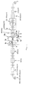
The method of manufacturing the battery can-forming plate of the
first embodiment is carried out in the procedure shown in Fig. 1.
As shown in Fig. 1, a hot-rolled steel plate 1, namely a hot coil, is
successively transported to each process to form a metal layer (nickel layer
in the first embodiment) on both surfaces of the plate 1, then wound as a
coil 2.
That is, initially, the hot-rolled plate 1 having a thickness 1mm - 6mm
is passed through an acid treatment device 3 to remove oxidized scale
formed on both surfaces thereof. Then, the hot rolled plate 1 is introduced
into a rinse tank 4 to wash it. Then, it is introduced into a drying oven 5 to
dry it.
Then, the hot rolled plate 1 is successively transported to a roll coater
(metal-coating device) 6. In the device, paste 7 consisting of metal powder
and screen oil or a binder added thereto is stored in tanks 8 and 8, and
rotation rollers 9a and 9a whose lower portions are immersed in the paste
are in contact with each of a pair of paste-applying rollers 10A and 10B.
The paste-applying rollers 10A and 10B are positioned vertically with a hot
coil transport path extending therebetween. Thus, the paste 7 supplied
from the tanks 8 and 8 to the surface of the paste-applying rollers 10A and
10B through the rotation rollers 9a and 9a, respectively is applied to the
upper and lower surfaces of the hot coil 1. Rolls 9b and 9b are in contact
with the rotation rolls 9a and 9a, respectively to drop excess paste.
As the metal powder forming the paste 7, Ni powder having a
diameter of 0.3µm - 10µm or a mixture of the nickel powder and powder of
other metal is used in the first embodiment. The metal mixed with the Ni
are selected from Al, In, Ca, Ag, Ge, Co, Sn, Sr, Se, Pb, Ba, Bi, Be, B, Mn, P,
Cr, Si, C, Cu, Fe, Zn, La, W, Ti, Mo, Ga and alloy thereof or mixture two or
more of the metals. Although the powder of these metals may be particulate,
scaly or flake-shaped, scaly or flake-shaped metal powder can be
preferably used.
The metal powder which can be used to coat both surfaces of the hot
roiled plate 1 is not limited to the Ni powder and a mixture of the Ni powder
and powder of other metal. For example, the powder of the above-listed
metals may be used.
The amount of the above metal powder which is applied to the hot
rolled plate 1 is set to 13g - 640g/m2. The metal powder and the screen oil
are mixed with each other at 50% - 75% of the metal powder and 50% - 25%
of the screen oil. Ordinary organic binder resin may be used instead of the
screen oil.
The method of applying the paste 7 consisting of the metal powder
and the screen oil to the hot rolled plate 1 is not limited to the method using
the roll coater, but other methods can be appropriately adopted.
After the paste 7 consisting of the metal powder and the screen oil is
applied to the upper and lower surfaces of the hot rolled plate 1, the hot
rolled plate 1 is introduced into a drying oven 11 and then into an annealing
oven 12. In the annealing oven 12, the metal powder is sintered at 600°C -
900°C for 1 - 30 minutes in a deoxidizing atmosphere (N2: 25% - 99%, H2;
75%- 1%).
The screen oil (or binder) is thermally decomposed and removed by
continuous annealing in the annealing oven 12, and Ni (and other metal
mixed with Ni) on the both surfaces of the steel plate is reduced by the
temperature and the deoxidizing gas.
Then, the plate 1 is passed through a pressure roll 13 at the normal
temperature - 500°C to roll them at rolling rate of 0.3% - 10%. The rolling
enhances the degree of the adhesion of the Ni powder to both surfaces of the
iron of the steel plate.
Then, the plate 1 is introduced into an annealing oven 14 to anneal at
600°C - 900°C for 1 - 2 minutes to form a diffusion layer between the iron of
the steel plate and the Ni layer or the layer of the mixture of Ni and other
metal. Then, the plate 1 is taken out from the annealing oven 14 and
introduced into a cooling oven 15 to cool so that the temperature of the plate
is reduced at 60°C.
The plate having the metal layer formed on both surfaces thereof is
wound as a coil 2.
Then, the plate having the metal (Ni) layer formed on its surface and
rewound from coil 2 is introduced into a cold rolling device to roll the plate at
rolling rate of 80% - 90% until the thickness of the plate is 103% - 101% of
the predetermined thickness of a final product. After the plate is cold rolled,
the plate is introduced into an annealing oven for annealing (550°C - 800°C,
24 hours - 48 hours) by the batch or for successive annealing (600°C -
900°C, 0.5 minutes - 3 minutes) in a deoxidizing atmosphere.
After the plate is annealed, the plate is rolled by a pair of skin pass
rollers at rolling rate of 0.3% - 3% so that a thickness of the plate, which is
used as a battery can-forming plate, become 0.1mm-o.8mm required. Then
the plate is wound as coil.
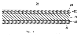
Referring to Fig. 2, in the battery can-forming plate 20 which is
manufactured by the method, a Ni-plated layer (or layer of mixture of Ni and
other metal) 23 is formed on either surface of a steel plate 21 through a
diffusion layer 22. The thickness of the steel plate 21 is 0.1mm - 0.8mm.
The thickness of the diffusion layer 22 is 0.1µm - 3µm. The thickness of
the Ni-plated layer 23 formed on both surfaces of the steel plate 21 is 1µm -
5 µm.
First Experiment
A hot-rolled steel plate (hot coil) having a thickness of 1.66mm was
acid-treated to remove oxidized scale. Then, the hot coil was washed with
water and dried. Then, 100 parts by weight of Ni powder (consisting of
powder having diameter 2 - 5µm contained at 80% and powder having
diameter 0.5µm contained at 20%) and 100 parts by weight of screen oil
were kneaded to obtain paste. The paste was applied by a roll coater to
either surface of the plate such that either surface was coated with 195g/m2
of the Ni powder. Then, the plate was annealed in a deoxidizing gas
consisting of N2 at 80% and H2 at 20% for three minutes at 800°C. Then,
using a rolling machine, the plate was successively rolled in a reducing
atmosphere at 400°C at a rolling rate of 3%. Thereafter, the plate was
annealed again in a reducing atmosphere at 800°C for two minutes. After
the plate was cooled to adjust the temperature of the steel plate to 60°C, it
was taken out to the atmospheric air. The thickness of the plate was
1.65mm at this time,
The hot-rolled plate having a thickness of 1.65mm and having a Ni
layer formed on either surface of the steel plate was cold-rolled at a rolling
rate 84.6% to adjust the thickness thereof to 0.255m. Thereafter, the
cold-roiled plate was annealed successively for one minute at 700°C in a
reducing atmosphere. Then, the cold-rolled plate was rolled by a skin pass
roller at a rolling rate of 2% to obtain a final product, namely, a battery
can-forming plate having a thickness of 0.25mm. The thickness of the Ni
layer was 2.9µm and that of the diffusion layer was 1.2µm.
Second Experiment
Using the same manufacturing method as that of the first experiment
and changing the kind of metal powder of the first experiment, a battery
can-forming plate was manufactured. Metal powder consisting of
Ni:97.9%, Fe;1.0%, Co:0.5%, C:0.2%, and Si:0.4% was used.
Fig. 3 shows the second embodiment of the present invention.
Similarly to the first embodiment, a metal layer consisting of Ni powder is
formed on the surface of the hot-rolled plate (hot coil). The second
embodiment is different from the first embodiment in that the Ni powder
was applied to the surface of the hot-rolled plate not in the form of paste but
spread thereon. The thickness of a metal powder layer is adjusted to a
predetermined one by a doctor knife. The metal layer consisting of the Ni
powder is also formed on the hot-rolled plate in the second embodiment.
But needless to say, the above-listed metal powders which are used in the
first embodiment may be used in the second embodiment.
The method of spreading metal powder is not limited to a specific
method, but a sieve may be used to spread it or a shoot may be used to
spread it between a pair of rollers.
In the second embodiment, as shown in Fig. 3, a hot-rolled steel plate
1 is introduced into an acid treatment device 3 to remove oxized scale from
the surface of the plate. Then, the plate 1 is introduced into a rinse tank 4
to wash it with water and is dried in a drying oven 5. Then, the plate 1 is
successively transported to a metal spreading device 30 in which the metal
powder is spread on the upper surface of the plate 1 by using a spreading
machine 33, then the thickness of the metal powder layer is adjusted to a
predetermined thickness by a doctor knife 31. Then, the plate 1 is passed
between a pair of compression rollers 32a and 32b vertically located to
compress the spread metal powder.
Then, the plate 1 is introduced into an annealing oven 12 to sinter the
metal powder at 600°C - 900°C for one minute - 30 minutes in a deoxidizing
atmosphere (N2: 25% - 99%, H2: 75% - 1%). Successively, the plate 1 is
rolled at rolling rate of 0.3% - 10% in a rolling machine 13, then it is
introduced into a cooling oven 34.
Then, the plate 1 is turned upside down to transport it with the lower
surface thereof at the upper side thereof. In this state, the metal powder is
deposited on the lower surface of the plate 1 in the same method as that
used to deposit it to the upper surface thereof. That is, the plate 1 is
introduced into a metal spreading device 30' to spread the metal powder to
the lower surface thereof by a spreading machine 33'. Then, the thickness
of the metal powder layer is adjusted to a required one by a doctor knife 31'.
Then, the plate 1 is passed between a pair of compression rollers 32a' and
32b' vertically arranged to compress the metal powder. Then, the plate 1 is
introduced into an annealing oven 12' to sinter the metal powder at 600°C -
900°C for 1 - 30 minutes in a deoxidizing atmosphere (N2: 25% - 99%, H2:
75% - 1%). Then, the plate 1 is rolled at rolling rate of 0.3% - 10% in a
rolling machine 13' and then, introduced into an annealing oven 35 and a
cooling oven 36 to adjust the temperature of the steel plate to 60°C. The
plate having the Ni layer formed on both surfaces thereof is wound around a
roll as a coil 2.
Then, the plate rewound from the coil 2 is introduced into a cold
rolling device to roll it at rolling rate of 80% - 90% until the plate is rolled to
103% - 101% of the predetermined thickness of a final product.
After the plate is cold-rolled, the plate is introduced into an annealing
oven for annealing (550°C - 800°C, 24 hours - 48 hours) by the batch or for
successive annealing (600°C - 900°C, 0.5 minutes - 3 minutes) in a
deoxidizing atmosphere. After the plate is annealed, the plate is rolled by a
skin pass roller at rolling rate of 0.3% - 3% so as to be a required thickness
of 0.1mm -0.8mm. Then, the plate used a battery can-forming plate 20 is
wound as a coil. Referring to Fig. 2, in the battery can-forming plate 20
which is manufactured by the method, a Ni plated layer (or layer of mixture
of Ni and other metal) 23 is formed on either surface of a steel plate 21
through a diffusion layer 22. The thickness of the steel plate 21 is 0.1mm -
0.8mm. The thickness of the diffusion layer 22 is 0.1µm - 3µm. The
thickness of the Ni-plated layer 23 formed on both surfaces of the steel plate
21 is 1µm - 5µm.
Third Experiment
Slab formed by casting was hot-rolled to form a hot coil (a hot-rolled
steel plate) having a thickness of 2.0mm. Then, oxidized scale was
removed from the hot-rolled plate by acid treatment. Then, the hot-rolled
plate was washed with water and dried. Then, using a spreading machine,
mixed metal powder consisting of Ni:98.7%, Fe:0,8%, B:0.2%, Ag:0.1%, and
Mn:0.2% was spread on the surface of the hot-rolled plate at 180g/m2, and
then, the thickness of a metal powder layer was adjusted by a doctor knife.
Then, the plate was annealed at 850°C for three minutes in a
deoxidizing gas consisting of N2 at 80% and H2 at 20%. Then, the plate was
successively rolled at a rolling rate of 1% at 400°C in a reducing atmosphere.
Then, the plate was turned upside down to spread mixed metal power to
the lower surface thereof by using a spreading machine in a method similar
to the above, Then, the thickness of the metal powder layer was adjusted to
a required one by a doctor knife. Then, the plate was annealed at 850°C
for three minutes in a reducing atmosphere. Then, the plate was
successively rolled at a rolling rate of 1% in a reducing atmosphere at 400°C
by a rolling machine. Then, the plate was annealed again at 800°C for two
minutes in a reducing atmosphere. After the plate was cooled to adjust the
temperature of the steel plate to 60°C, it was taken out to the atmospheric
air. The thickness of the plate was 1.99mm at this time.
The plate which having a thickness of 1.99mm and having the Ni
alloy layer formed on the surface thereof was cold-rolled at a rolling rate of
84.6% to adjust the thickness thereof to 0.306m. Thereafter, the plate was
annealed successively for one minute at 750°C in a reducing atmosphere.
Then, the plate was rolled by a skin pass roller at a rolling rate of 2% to
obtain a final product, namely, a battery can-forming plate having a
thickness of 0.3mm. The thickness of the Ni alloy layer was 2.8µm and
that of the diffusion layer was 1.6µm.
Fig. 4 shows the third embodiment of the present invention. The third
embodiment is different from the first and second embodiments in that,
instead of forming a metal layer consisting of metal powder on the surface of
the hot-rolled steel plate, a plated layer (in the third embodiment, Ni-plated
layer) is formed thereon by electroplating.
That is, a hot-rolled steel plate1 is introduced into an acid treatment
device 3 to remove oxidized scale formed on the surface thereof. Then, the
hot coil 1 was washed with water in a rinse tank 4. After the plate 1 is
introduced into a neutralizing device 40, it is introduced into a rinse tank 41.
Then, it is introduced into a plating tank 42 to plate both surfaces of the
hot-rolled steel plate 1. After the hot-rolled steel plate 1 is electroplated in
the plating tank 42, it is washed with water in a rinse tank 43. Then, it is
introduced into a drying oven 44 to dry it.
Then, the plate 1 having the metal plated thereon is annealed in a
reducing atmosphere at 600°C - 900°C. Then, the plate 1 is rolled at the
normal temperature - 500°C at rolling rate of 0.3% - 5% in a rolling machine
46. Thereafter, the plate 1 is introduced into a cooling oven 47 to cool it.
As a result, a plate having the Ni-plated layer thereon is formed.
When the plated metal layer is thin, it is unnecessary to anneal the
plate. In the third embodiment, the steel plate is thick and the plated layer
is also thick because the steel plate and the plated layer are cold-rolled
after
the steel plate is plated. Thus, the plated layer is liable to be separated
from the steel plate. In order to prevent this, the diffusion layer is formed
between the steel plate and the plated metal layer.
Then, the hot-rolled plate having the Ni plated layers on both surfaces
thereof is introduced into a cold rolling device to roll it at rolling rate of 80%
- 90%, until the thickness of the plate is 103% - 101% of the predetermined
thickness of a final product.
After the plate is cold-rolled, the plate is introduced into an annealing
oven for annealing (550°C - 800°C, 24 hours - 48 hours) by the batch or
successive annealing (600°C - 900°C, 0.5 minutes - 3 minutes) in a
deoxidizing atmosphere. After the plate is annealed, the plate is rolled by a
skin pass roller at rolling rate of 0.3% - 3% so as to be a required thickness
of 0.1mm - 0.8mm, then the plate used for a battery can-forming plate is
wound as a coil. Referring to Fig. 2, in the battery can-forming plate 20
which is manufactured thus, a Ni-plated layer (or layer of mixture of Ni and
other metal) 23 is formed on either surface of a steel plate 21 through a
diffusion layer 22. The thickness of the steel plate 21 is 0.1mm - 0.8mm.
The thickness of the diffusion layer 22 is 0.1µm - 3µm. The thickness of
the Ni-plated layer 23 is 1µm - 5µm.
Fourth Experiment
Iron slab formed by casting was hot-rolled to form a hot -rolled plate
(hot coil) having a thickness of 2.67mm. Then, oxidized scale was removed
from the plate by acid treatment. Then, the plate was washed with water,
neutralized, and washed. Then, the hot coil was Ni-plated in Watts bath to
form a nickel-plated layer having a thickness of 22µm on each of both
surfaces (44µm on both surfaces) thereof.
Then, the plate having the nickel-plated layer formed thereon was
annealed in a deoxidizing gas consisting of N2 at 80% and H2 at 20% at
750°C for three minutes. Then, using a rolling machine, the hot coil was
successively rolled in a reducing atmosphere at 400°C at a rolling rate of 2%.
After the plate was cooled to adjust the temperature of the steel plate 60°C,
it was taken out to the atmospheric air. The thickness of the plate was
2.66mm at this tune.
The plate having a thickness of 2.66mm and the Ni layer formed on
the surface thereof was cold-rolled at a rolling rate of 84.6% to adjust the
thickness thereof to 0.41m. Thereafter, the plate was annealed by the
batch in a reducing atmosphere at 600°C for 24 hours. Then, the plate was
rolled by a skin pass roller at a rolling rate of 2.5% to obtain a final product,
namely, a battery can-forming plate having a thickness of 0.4mm. The
thickness of the Ni layer was 3µm and that of the diffusion layer was 1.4µm.
The thickness of the battery can-forming plate manufactured by the
method of the first through fourth experiments and the components thereof
are as shown in table 2 shown below. The mechanical characteristics of
each battery can-forming plate, namely, the YP (yield point), TS (tensile
strength), EL (elongation), HR-30T (hardness) thereof, and the thickness of
the diffusion layer thereof are also as shown in table 2.
As shown in table 2, the yield point, tensile strength, and elongation
of the battery can-forming plate of each of the first through fourth
experiments were almost equal to those of a conventional battery can-forming
plate manufactured by plating a cold-rolled steel plate having a
final thickness and those of a battery can-forming plate manufactured by
plating a cold-rolled steel plate and then annealing and rolling it to have a
final thickness.
It was confirmed that the manufacturing method of the present
invention, in which metal layer on the hot-rolled steel plate (hot coil) is
formed by plating it directly or spreading metal powder thereon or coating
metal powder on the hot-rolled steel plate, is more productive and much
less costly than the conventional manufacturing method. Further, it was
confirmed that the battery can-forming plate of the present invention have a
quality similar to that of the battery can-forming plate manufactured by the
conventional method.
Comparison tests were conducted on the battery can-forming plate of
the first through fourth experiments, a conventional example 1( nickel was
plated on only iron plate), and a conventional example 2 (nickel was plated
on iron plate, then the plate was annealed and rolled by skin pass roller) to
compare the corrosion resistance, press drawing property, and separation
property thereof.
In accordance with JIS Z 2371, the corrosion resistance test was
carried out.
In order to carry out the method of testing the press drawing property,
battery cans were formed of the battery can-forming plate of the first
through fourth experiments of the present invention and that of the
conventional examples 1 and 2 by using press drawing. That is, the
battery cans were formed by using three kinds of drawing processes, namely,
transfer drawing, DI (drawing and ironing), and drawing in combination of
transfer drawing and DI.
In order to carry out the method of testing the separation property,
the battery can-forming plates were bent by 360° three times to visually
inspect the degree of separation of the metal layer formed on the surface of
the steel plate.
Table 3 shown below shows the result of the corrosion test, the press
drawing property test, and the separation property test. In the table 3, X
indicates "worst", ▵ indicates "worse", O indicates "good", and o ○ indicates
"best". The separation property means the degree of adhesion between the
steel plate and the nickel layer formed thereon. "Good separation" means
that the steel plate and the nickel layer are not separated from each other
but stably kept in an adhesive state.
| | Corrosion Resistance | Press Drawing Property | Separation Property |
| Conventional example 1 | ▵ | O | O |
| Conventional example 2 | O | O | O |
| Experiment 1 | O | O | o ○ |
| Experiment 2 | O | O | o ○ |
| Experiment 3 | O | O | o ○ |
| Experiment 4 | o ○ | O | o ○ |
X···worst, ▵···worse, O···good, o ○···best
Conventional example 1 (Nickel plating on iron plate)
Conventional example 2 (Nickel plating on iron plate□Annealing□Skin pass rolling) |
As indicated in the table 3, the battery can-forming plate of each of
the first through fourth experiments of the present invention was good in
the corrosion resistance, the press drawing property, and the separation
property and excellent in the separation property.
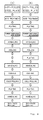
The present invention is not limited to the first through third
embodiments, the battery can-forming plate of the present invention can be
manufactured by various processes as shown in Figs. 5A, 5B, 5C, and 5D;
Figs. 6A, 6B, 6C, and 6D; Figs. 7A, 7B, and 7C; and Figs. 8A and 8B.
Although in each of the first through fourth embodiments, the metal
layer which is formed on either surface of the hot-rolled plate consists of the
same kind of metal, the layer which is formed on the upper surface thereof
and that which is formed on the lower surface thereof may consist of
different kinds of metal. For example, a Ni-plated layer may be formed on
one surface thereof, whereas a layer of aluminum powder may be formed on
the other surface thereof.
Further, different kinds of metal layers may be laminated on the
surface of a steel plate. For example, a layer of aluminum powder may be
formed on the surface of the nickel-plated layer. Furthermore, two or more
metal layers may be laminated on each surface of the plate.
The battery cans were formed by using the known battery can-forming
method, namely, transfer drawing, DI or drawing in combination of
transfer drawing and DI. As confirmed in the test, because the battery
can-forming plate of the present invention is preferable in press drawing
property, it is superior in processability as well.
As apparent from the foregoing description, according to the present
invention, replacing the conventional method of cold-rolling a hot-rolled
steel plate (hot coil) to make the thickness thereof thin and plating the
cold-rolled steel plate, metal powder is spread on the hot-roiled steel plate or
applied thereto in the form of slurry to form a metal layer thereon.
Therefore, the length per unit weight in the hot-rolled steel plate is shorter
than that of the steel plate which is cold-rolled to a required thickness. The
method of the present invention allows the surface area of the steel plate
which is treated to be smaller than that of the steel plate which is treated by
the conventional method, thus forming the metal layer consisting of metal
powder or the plated metal layer in a short period of time. In result, the
method of the present invention enhances the productivity, thus accomplishing
a great deal of surface-treating operation in a short period of time.
In particular, when metal powder is spread on the hot-rolled steel
plate or applied thereto in the form of slurry to form a metal layer thereon
and plating operation is omitted, it is unnecessary to use a large plating
apparatus and possible to consume no electric power. Therefore, the
method of the present invention allows the battery can-forming plate to be
manufactured with reducing cost much.
Further, in the present invention, the plated layer or/and the metal
layer consisting of metal powder are formed on the surface of the steel plate,
the only small area may be surface- treated. It allows the total manufacturing
cost can be reduced by about 25% compared to that of the conventional
method of surface-treating the cold-rolled steel plate.
Furthermore, in the present invention, a battery can-forming plate of
the same thickness and width that the conventional battery can-forming
plate has can be manufactured with reducing the required period to about
1/7 of the period by the conventional manufacturing method (after steel
plate is hot-rolled, it is cold-rolled, and then, plated).