EP0883777B1 - HIGH-HEAT TRANSFER, LOW-NOx COMBUSTION SYSTEM - Google Patents
HIGH-HEAT TRANSFER, LOW-NOx COMBUSTION SYSTEM Download PDFInfo
- Publication number
- EP0883777B1 EP0883777B1 EP97907953A EP97907953A EP0883777B1 EP 0883777 B1 EP0883777 B1 EP 0883777B1 EP 97907953 A EP97907953 A EP 97907953A EP 97907953 A EP97907953 A EP 97907953A EP 0883777 B1 EP0883777 B1 EP 0883777B1
- Authority
- EP
- European Patent Office
- Prior art keywords
- fuel
- preheated
- combustion
- oxidant
- accordance
- Prior art date
- Legal status (The legal status is an assumption and is not a legal conclusion. Google has not performed a legal analysis and makes no representation as to the accuracy of the status listed.)
- Expired - Lifetime
Links
Images


Classifications
-
- F—MECHANICAL ENGINEERING; LIGHTING; HEATING; WEAPONS; BLASTING
- F23—COMBUSTION APPARATUS; COMBUSTION PROCESSES
- F23C—METHODS OR APPARATUS FOR COMBUSTION USING FLUID FUEL OR SOLID FUEL SUSPENDED IN A CARRIER GAS OR AIR
- F23C3/00—Combustion apparatus characterised by the shape of the combustion chamber
- F23C3/006—Combustion apparatus characterised by the shape of the combustion chamber the chamber being arranged for cyclonic combustion
-
- C—CHEMISTRY; METALLURGY
- C03—GLASS; MINERAL OR SLAG WOOL
- C03B—MANUFACTURE, SHAPING, OR SUPPLEMENTARY PROCESSES
- C03B5/00—Melting in furnaces; Furnaces so far as specially adapted for glass manufacture
- C03B5/16—Special features of the melting process; Auxiliary means specially adapted for glass-melting furnaces
- C03B5/235—Heating the glass
-
- C—CHEMISTRY; METALLURGY
- C03—GLASS; MINERAL OR SLAG WOOL
- C03B—MANUFACTURE, SHAPING, OR SUPPLEMENTARY PROCESSES
- C03B5/00—Melting in furnaces; Furnaces so far as specially adapted for glass manufacture
- C03B5/16—Special features of the melting process; Auxiliary means specially adapted for glass-melting furnaces
- C03B5/235—Heating the glass
- C03B5/237—Regenerators or recuperators specially adapted for glass-melting furnaces
-
- F—MECHANICAL ENGINEERING; LIGHTING; HEATING; WEAPONS; BLASTING
- F23—COMBUSTION APPARATUS; COMBUSTION PROCESSES
- F23C—METHODS OR APPARATUS FOR COMBUSTION USING FLUID FUEL OR SOLID FUEL SUSPENDED IN A CARRIER GAS OR AIR
- F23C6/00—Combustion apparatus characterised by the combination of two or more combustion chambers or combustion zones, e.g. for staged combustion
- F23C6/04—Combustion apparatus characterised by the combination of two or more combustion chambers or combustion zones, e.g. for staged combustion in series connection
- F23C6/045—Combustion apparatus characterised by the combination of two or more combustion chambers or combustion zones, e.g. for staged combustion in series connection with staged combustion in a single enclosure
- F23C6/047—Combustion apparatus characterised by the combination of two or more combustion chambers or combustion zones, e.g. for staged combustion in series connection with staged combustion in a single enclosure with fuel supply in stages
-
- F—MECHANICAL ENGINEERING; LIGHTING; HEATING; WEAPONS; BLASTING
- F23—COMBUSTION APPARATUS; COMBUSTION PROCESSES
- F23C—METHODS OR APPARATUS FOR COMBUSTION USING FLUID FUEL OR SOLID FUEL SUSPENDED IN A CARRIER GAS OR AIR
- F23C7/00—Combustion apparatus characterised by arrangements for air supply
- F23C7/02—Disposition of air supply not passing through burner
- F23C7/06—Disposition of air supply not passing through burner for heating the incoming air
-
- F—MECHANICAL ENGINEERING; LIGHTING; HEATING; WEAPONS; BLASTING
- F23—COMBUSTION APPARATUS; COMBUSTION PROCESSES
- F23D—BURNERS
- F23D14/00—Burners for combustion of a gas, e.g. of a gas stored under pressure as a liquid
- F23D14/32—Burners for combustion of a gas, e.g. of a gas stored under pressure as a liquid using a mixture of gaseous fuel and pure oxygen or oxygen-enriched air
-
- F—MECHANICAL ENGINEERING; LIGHTING; HEATING; WEAPONS; BLASTING
- F23—COMBUSTION APPARATUS; COMBUSTION PROCESSES
- F23D—BURNERS
- F23D14/00—Burners for combustion of a gas, e.g. of a gas stored under pressure as a liquid
- F23D14/46—Details
- F23D14/66—Preheating the combustion air or gas
-
- F—MECHANICAL ENGINEERING; LIGHTING; HEATING; WEAPONS; BLASTING
- F23—COMBUSTION APPARATUS; COMBUSTION PROCESSES
- F23L—SUPPLYING AIR OR NON-COMBUSTIBLE LIQUIDS OR GASES TO COMBUSTION APPARATUS IN GENERAL ; VALVES OR DAMPERS SPECIALLY ADAPTED FOR CONTROLLING AIR SUPPLY OR DRAUGHT IN COMBUSTION APPARATUS; INDUCING DRAUGHT IN COMBUSTION APPARATUS; TOPS FOR CHIMNEYS OR VENTILATING SHAFTS; TERMINALS FOR FLUES
- F23L15/00—Heating of air supplied for combustion
- F23L15/04—Arrangements of recuperators
-
- F—MECHANICAL ENGINEERING; LIGHTING; HEATING; WEAPONS; BLASTING
- F23—COMBUSTION APPARATUS; COMBUSTION PROCESSES
- F23L—SUPPLYING AIR OR NON-COMBUSTIBLE LIQUIDS OR GASES TO COMBUSTION APPARATUS IN GENERAL ; VALVES OR DAMPERS SPECIALLY ADAPTED FOR CONTROLLING AIR SUPPLY OR DRAUGHT IN COMBUSTION APPARATUS; INDUCING DRAUGHT IN COMBUSTION APPARATUS; TOPS FOR CHIMNEYS OR VENTILATING SHAFTS; TERMINALS FOR FLUES
- F23L7/00—Supplying non-combustible liquids or gases, other than air, to the fire, e.g. oxygen, steam
-
- F—MECHANICAL ENGINEERING; LIGHTING; HEATING; WEAPONS; BLASTING
- F23—COMBUSTION APPARATUS; COMBUSTION PROCESSES
- F23D—BURNERS
- F23D2900/00—Special features of, or arrangements for burners using fluid fuels or solid fuels suspended in a carrier gas
- F23D2900/00004—Burners specially adapted for generating high luminous flames, e.g. yellow for fuel-rich mixtures
-
- F—MECHANICAL ENGINEERING; LIGHTING; HEATING; WEAPONS; BLASTING
- F23—COMBUSTION APPARATUS; COMBUSTION PROCESSES
- F23L—SUPPLYING AIR OR NON-COMBUSTIBLE LIQUIDS OR GASES TO COMBUSTION APPARATUS IN GENERAL ; VALVES OR DAMPERS SPECIALLY ADAPTED FOR CONTROLLING AIR SUPPLY OR DRAUGHT IN COMBUSTION APPARATUS; INDUCING DRAUGHT IN COMBUSTION APPARATUS; TOPS FOR CHIMNEYS OR VENTILATING SHAFTS; TERMINALS FOR FLUES
- F23L2900/00—Special arrangements for supplying or treating air or oxidant for combustion; Injecting inert gas, water or steam into the combustion chamber
- F23L2900/15042—Preheating combustion air by auxiliary combustion, e.g. in a turbine
-
- Y—GENERAL TAGGING OF NEW TECHNOLOGICAL DEVELOPMENTS; GENERAL TAGGING OF CROSS-SECTIONAL TECHNOLOGIES SPANNING OVER SEVERAL SECTIONS OF THE IPC; TECHNICAL SUBJECTS COVERED BY FORMER USPC CROSS-REFERENCE ART COLLECTIONS [XRACs] AND DIGESTS
- Y02—TECHNOLOGIES OR APPLICATIONS FOR MITIGATION OR ADAPTATION AGAINST CLIMATE CHANGE
- Y02E—REDUCTION OF GREENHOUSE GAS [GHG] EMISSIONS, RELATED TO ENERGY GENERATION, TRANSMISSION OR DISTRIBUTION
- Y02E20/00—Combustion technologies with mitigation potential
- Y02E20/34—Indirect CO2mitigation, i.e. by acting on non CO2directly related matters of the process, e.g. pre-heating or heat recovery
-
- Y—GENERAL TAGGING OF NEW TECHNOLOGICAL DEVELOPMENTS; GENERAL TAGGING OF CROSS-SECTIONAL TECHNOLOGIES SPANNING OVER SEVERAL SECTIONS OF THE IPC; TECHNICAL SUBJECTS COVERED BY FORMER USPC CROSS-REFERENCE ART COLLECTIONS [XRACs] AND DIGESTS
- Y02—TECHNOLOGIES OR APPLICATIONS FOR MITIGATION OR ADAPTATION AGAINST CLIMATE CHANGE
- Y02P—CLIMATE CHANGE MITIGATION TECHNOLOGIES IN THE PRODUCTION OR PROCESSING OF GOODS
- Y02P40/00—Technologies relating to the processing of minerals
- Y02P40/50—Glass production, e.g. reusing waste heat during processing or shaping
-
- Y—GENERAL TAGGING OF NEW TECHNOLOGICAL DEVELOPMENTS; GENERAL TAGGING OF CROSS-SECTIONAL TECHNOLOGIES SPANNING OVER SEVERAL SECTIONS OF THE IPC; TECHNICAL SUBJECTS COVERED BY FORMER USPC CROSS-REFERENCE ART COLLECTIONS [XRACs] AND DIGESTS
- Y02—TECHNOLOGIES OR APPLICATIONS FOR MITIGATION OR ADAPTATION AGAINST CLIMATE CHANGE
- Y02P—CLIMATE CHANGE MITIGATION TECHNOLOGIES IN THE PRODUCTION OR PROCESSING OF GOODS
- Y02P40/00—Technologies relating to the processing of minerals
- Y02P40/50—Glass production, e.g. reusing waste heat during processing or shaping
- Y02P40/57—Improving the yield, e-g- reduction of reject rates
Definitions
- This invention relates to a process and apparatus for oxygen-enriched combustion of fuel, preferably natural gas, in which the fuel is preheated and burned in a manner which enhances in-flame soot formation and flame luminosity.
- fuel preferably natural gas
- New environmental requirements are a major driving force today for the development of new combustion methods and apparatuses. Manufacturers are being forced to reduce emissions, all the while striving to control costs and maintain product quality. For example, the glass industry is faced with the need to reduce NO x emissions significantly. In response thereto, advanced combustion systems, oxygen-enrichment, and oxygen-fuel combustion are being developed. In those instances where fuel and oxygen are essentially free of nitrogen, NO x emissions can be significantly reduced. However, nitrogen is often found in fuel as well as in oxygen produced by more cost efficient processes. Raw material feed stocks, such as glass mixing feed stocks, and air infiltration into an industrial furnace can also introduce nitrogen into the flame.
- U.S. Patent No. 5,057,133 and U.S. Patent No. 4,909,727 both teach modification of a fuel by preheating to produce a reformed and/or cracked fuel which is subsequently introduced into a combustion chamber for burning.
- the '133 patent teaches the use of furnace waste heat from an oxygen-enriched glass melting furnace to heat a reformer for partially reforming a fuel to produce a synthesis gas which is subsequently burned in the glass melting furnace.
- the '721 patent teaches a combustion process in which a portion of the fuel to be burned is cracked using oxygen-enriched air producing a cracked fuel, including soot, which is subsequently introduced into a combustion chamber with a second portion of fuel, producing a highly luminous flame.
- Patent 5,216,968 teaches reduction of NO x emissions in a combustion process by preheating a fuel gas in a chamber separate and apart from a main combustion chamber to a temperature above the ignition temperature of the fuel gas and introducing the preheated fuel gas into the main combustion chamber where it mixes with an oxygen-containing gas and is burned.
- U.S. Patent 5,139,755 which teaches a reburning process for reducing NO x emissions in which reducing agents are introduced into a reburn zone of a combustion process, said reducing agents including fuel, to produce an oxygen deficient reburn zone
- U.S. Patent 5,180,300 which teaches a low NO x regenerative burner having a regenerative bed for preheating combustion air in which fuel is burned in stages and flue gases generated by the combustion process are recirculated into the combustion zones.
- U.S. Patent 4,488,866 teaches a process and apparatus for burning high-nitrogen, high-sulfur fuels in which the fuel is first treated to remove SO x precursors and the resulting fuel is then burned in a two-step process, a first fuel-rich stage followed by a second fuel-lean stage.
- U.S. Patent 5,043,232 teaches a fuel processing system suitable for gas and liquid fuels for use in connection with fuel cell power generation systems in which the fuel is preheated in a heat exchanger for use in the fuel cell power generation system.
- Patent 5,161,366 teaches a gas turbine catalytic combustor having a preburner in which combustion products from the preburner are mixed with a hydrocarbon fuel in the presence of a combustion catalyst to ignite and initiate a catalytic combustion reaction after which the preburner is then shut down.
- U.S. Patent 3,975,138 teaches an oil burner in which the liquid fuel is thermally cracked to produce gaseous hydrocarbons which are subsequently burned.
- US-A-5,248,252 discloses a process and apparatus for combustion of a gaseous fuel in which the gaseous fuel is preheated to form soot and the soot, thus formed, is mixed with an oxidant and ignited to form a highly luminous flame.
- WO-A-9,002,907 discloses a process and an apparatus in which a first oxidizing gas containing a high oxygen concentration is injected as a stream into the central zone of a combustion tunnel and a part of the fuel is injected into the central pyrolisis zone to mix with the first oxidizing gas to create a highly luminous, high temperature flame core. The remaining part of the fuel is injected in a plurality of streams about said flame core to mix with the second oxidizing gas.
- JP-63315814 A discloses a process and an apparatus for combustion of a mixture of fuel and oxidant as defined respectively in the preamble of claim 1 and claim 12.
- a process for combustion of a fuel/oxidant mixture according to claim 1. This process increases the heat transfer from the flame to the load being treated and reduces NO x formation.
- the fuel is natural gas and the oxidant is oxygen or oxygen-enriched air.
- Preheating of the fuel is accomplished in accordance with this process by preburning a portion of the fuel or in a furnace heat recovery system, that is, by exchanging heat with flue products exhausted from the combustion process and by preburning a portion of the fuel with an oxidant and transferring at least a portion of the heat in the resulting precombustion products to the remaining portion of the fuel indirectly through a heat exchanger and/or directly by mixing and mixing the resulting precombustion products with the remaining portion of fuel.
- preheated fuel in accordance with the process of this invention produces reduced NO x emissions in the presence of nitrogen, improves the rate of heat transfer from the resulting flame to a load being processed, and reduces heat losses resulting from the ejection of high temperature flue gases from the combustion process.
- Preheated fuel in particular natural gas, produces a more luminous flame, thus improving heat transfer and reducing flame temperature which, in turn, results in NO x formation reduction.
- Improved heat transfer provides benefits such as increased productivity and, eventually, smaller, more cost effective furnaces. These benefits increase even more where heat recovery from the flue gas is used for preheating fuel alone or in combination with a recuperator to produce hot partially reformed fuel.
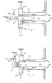
- Fig. 1 shows a schematic diagram of an oxygen-fuel burner design utilizing the process of this invention in which a portion of the fuel to be burned is burned separately within a burner space using oxygen in a precombustion zone. Hot gases so produced are used for preheating the remaining portion of the fuel stream in a preheating zone. The preheated fuel is then supplied to a furnace for combustion.
- This type of fuel is capable of producing soot when firing with an appropriate amount of industrial oxygen resulting in a significant increase in flame luminosity, improved heat transfer and reduced NO x emissions.
- a first portion of the fuel to be burned in the combustion process is introduced through precombustor fuel inlet 23a into precombustor 25 and precombustion oxidant, preferably oxygen or oxygen-enriched air, is introduced through precombustor oxidant inlet 24a into precombustor 25 in which the resulting oxidant-fuel mixture is burned, forming fuel precombustion zone 20.
- precombustion oxidant preferably oxygen or oxygen-enriched air
- precombustion oxidant preferably oxygen or oxygen-enriched air
- the preheating of fuel in first fuel preheat zone 21a and second fuel preheat zone 21b may be enhanced by utilizing a combustor in which said zones are formed by metallic walls which are protected from overheating by the flowing fuel and oxidant.
- the resulting preheated fuel is subsequently mixed in main combustion zone 22 with primary combustion oxidant introduced into main combustion zone 22 through primary combustion oxidant inlet 24b.
- the primary combustion oxidant introduced through primary combustion oxidant inlet 24b may be preheated by indirect means in oxidant preheating zone 21c.
- flame temperature is maintained generally below the level required for significant formation of NO x emissions.
- controlled mixing we mean a slow, generally non-turbulent mixing as opposed to a rapid, highly turbulent mixing whereby fuel-rich zones are created within the flame in which at least a portion of the fuel is further heated to above about 1093°C (2000°F) in the absence of sufficient oxygen for complete combustion, thereby cracking a portion of the fuel to form soot.
- cyclonic chamber 30 as shown in Fig. 2, is employed as a precombustor, fuel and oxidant being premixed and/or directly introduced into cyclonic chamber 30 in a manner which imparts a swirl to the combustion products.
- cyclonic chamber 30 as a precombustor in accordance with one embodiment of this invention produces high intensity, efficient combustion, low level of NO x emissions within cyclonic chamber 30, and high heat transfer to the combustor walls and in the fuel preheating zone due to the swirling patterns within cyclonic chamber 30.
- Fig. 3 shows a schematic diagram of an oxygen-fuel burner design utilizing the process of this invention in accordance with yet another embodiment of the burner of this invention.
- the secondary oxidant introduced through oxidant inlet 24b is provided to main combustion zone 22 in stages, a first portion of said oxidant mixing at an upstream end of main combustion zone 22 proximate the exit of the combustor and a second portion of said oxidant mixing downstream thereof as shown by arrows 26 and 27, respectively.
- the temperature of the preheated fuel/oxidant mixture at the exit of the combustor is preferably in the range of about 982°C (1800°F) to 1315°C (2400°F).
- Operation within this temperature range is important for minimizing the formation of NO x within the flame.
- introducing the secondary oxidant into main combustion zone 22 in stages produces a fuel-rich zone within the center portion (core) of the flame, thereby promoting the formation of soot within the flame, and an oxidant-rich zone surrounding the flame core, thus ensuring complete combustion of the fuel.
- Fig. 4 shows a schematic diagram of an oxygen-fuel burner design utilizing the process of this invention in accordance with yet another embodiment of the burner of this invention.
- all of the fuel is introduced into the combustor in a single stage and mixed with a portion of the oxidant required for complete combustion of the fuel, resulting in partial combustion of a portion of the fuel and preheating of the remaining portion of the fuel.
- the temperature of the resulting mixture of products of partial combustion and preheated fuel proximate the exit end of the combustor is preferably in the range of about 982°C (1800°F) to 1315°C (2400°F).
- Secondary oxidant is then introduced into the combustor through oxidant inlet 24b and passes in an annular region surrounding cyclonic combustion chamber 30 to the exit end of the combustor, enveloping the mixture of products of partial combustion and preheated fuel so as to form soot in main combustion zone 22 and enhance luminosity of the resulting flame.
- Fig. 5 is a schematic diagram of a regenerative glass melter employing a high-heat transfer, low NO x oxygen-fuel combustion system as shown in Fig. 1 as an example of a furnace with heat recovery utilizing combustion air as the main oxidant.
- fuel used for firing in regenerative glass melter 40 is preheated up to 538°C (1000°F) in heat exchanger 42 utilizing waste heat from regenerators 41 and then injected into the burner as two separate streams.
- One stream is used for firing with oxidant within precombustor 25 to preheat the other stream to temperatures up to about 1093°C (2000°F).
- the resulting fuel is then mixed with combustion air within main combustion zone 22 and burned. It will be apparent to those skilled in the art that this invention is employable in other types of furnaces with heat recovery, such as recuperative furnaces.
Landscapes
- Engineering & Computer Science (AREA)
- Chemical & Material Sciences (AREA)
- Combustion & Propulsion (AREA)
- Mechanical Engineering (AREA)
- General Engineering & Computer Science (AREA)
- Physics & Mathematics (AREA)
- Thermal Sciences (AREA)
- Materials Engineering (AREA)
- Organic Chemistry (AREA)
- Combustion Of Fluid Fuel (AREA)
Abstract
Description
- This invention relates to a process and apparatus for oxygen-enriched combustion of fuel, preferably natural gas, in which the fuel is preheated and burned in a manner which enhances in-flame soot formation and flame luminosity.
- New environmental requirements are a major driving force today for the development of new combustion methods and apparatuses. Manufacturers are being forced to reduce emissions, all the while striving to control costs and maintain product quality. For example, the glass industry is faced with the need to reduce NOx emissions significantly. In response thereto, advanced combustion systems, oxygen-enrichment, and oxygen-fuel combustion are being developed. In those instances where fuel and oxygen are essentially free of nitrogen, NOx emissions can be significantly reduced. However, nitrogen is often found in fuel as well as in oxygen produced by more cost efficient processes. Raw material feed stocks, such as glass mixing feed stocks, and air infiltration into an industrial furnace can also introduce nitrogen into the flame. As a result, all of these sources of nitrogen can result in increased NOx emissions, thereby negating part of the NOx reduction benefit derived from using oxygen in the combustion process. In addition, because of the high cost of oxygen and the absence of highly effective heat-recovery from the flue gases, operating costs can also increase. Accordingly, in applications using oxygen-enriched fuel combustion, there is a clear need for reducing NOx emissions by improving heat transfer from the flame to the load being heated, and recovering heat from the flue gases exhausted by the combustion process.
- U.S. Patent No. 5,057,133 and U.S. Patent No. 4,909,727 both teach modification of a fuel by preheating to produce a reformed and/or cracked fuel which is subsequently introduced into a combustion chamber for burning. The '133 patent teaches the use of furnace waste heat from an oxygen-enriched glass melting furnace to heat a reformer for partially reforming a fuel to produce a synthesis gas which is subsequently burned in the glass melting furnace. The '721 patent teaches a combustion process in which a portion of the fuel to be burned is cracked using oxygen-enriched air producing a cracked fuel, including soot, which is subsequently introduced into a combustion chamber with a second portion of fuel, producing a highly luminous flame. U.S. Patent 5,216,968 teaches reduction of NOx emissions in a combustion process by preheating a fuel gas in a chamber separate and apart from a main combustion chamber to a temperature above the ignition temperature of the fuel gas and introducing the preheated fuel gas into the main combustion chamber where it mixes with an oxygen-containing gas and is burned.
- Other methods of reducing NOx emissions from combustion processes are taught by U.S. Patent 5,139,755 which teaches a reburning process for reducing NOx emissions in which reducing agents are introduced into a reburn zone of a combustion process, said reducing agents including fuel, to produce an oxygen deficient reburn zone and U.S. Patent 5,180,300 which teaches a low NOx regenerative burner having a regenerative bed for preheating combustion air in which fuel is burned in stages and flue gases generated by the combustion process are recirculated into the combustion zones.
- U.S. Patent 4,488,866 teaches a process and apparatus for burning high-nitrogen, high-sulfur fuels in which the fuel is first treated to remove SOx precursors and the resulting fuel is then burned in a two-step process, a first fuel-rich stage followed by a second fuel-lean stage. U.S. Patent 5,043,232 teaches a fuel processing system suitable for gas and liquid fuels for use in connection with fuel cell power generation systems in which the fuel is preheated in a heat exchanger for use in the fuel cell power generation system. U.S. Patent 5,161,366 teaches a gas turbine catalytic combustor having a preburner in which combustion products from the preburner are mixed with a hydrocarbon fuel in the presence of a combustion catalyst to ignite and initiate a catalytic combustion reaction after which the preburner is then shut down. Finally, U.S. Patent 3,975,138 teaches an oil burner in which the liquid fuel is thermally cracked to produce gaseous hydrocarbons which are subsequently burned.
- US-A-5,248,252 discloses a process and apparatus for combustion of a gaseous fuel in which the gaseous fuel is preheated to form soot and the soot, thus formed, is mixed with an oxidant and ignited to form a highly luminous flame.
- WO-A-9,002,907 discloses a process and an apparatus in which a first oxidizing gas containing a high oxygen concentration is injected as a stream into the central zone of a combustion tunnel and a part of the fuel is injected into the central pyrolisis zone to mix with the first oxidizing gas to create a highly luminous, high temperature flame core. The remaining part of the fuel is injected in a plurality of streams about said flame core to mix with the second oxidizing gas.
- JP-63315814 A (OSAKA GAS) discloses a process and an apparatus for combustion of a mixture of fuel and oxidant as defined respectively in the preamble of
claim 1 and claim 12. - None of the prior art references cited hereinabove simultaneously address the combination of reduced NOx emissions and improved heat transfer from a flame using industrial oxygen for fuel preheat.
- Accordingly, it is an object of this invention to provide a process and apparatus for combustion producing enhanced flame luminosity.
- It is another object of this invention to provide a process and apparatus for combustion of a fuel which produces low NOx emissions.
- These and other objects of this invention are achieved by a process for combustion of a fuel/oxidant mixture according to
claim 1. This process increases the heat transfer from the flame to the load being treated and reduces NOx formation. In accordance with a preferred embodiment of this invention, the fuel is natural gas and the oxidant is oxygen or oxygen-enriched air. - Preheating of the fuel is accomplished in accordance with this process by preburning a portion of the fuel or in a furnace heat recovery system, that is, by exchanging heat with flue products exhausted from the combustion process and by preburning a portion of the fuel with an oxidant and transferring at least a portion of the heat in the resulting precombustion products to the remaining portion of the fuel indirectly through a heat exchanger and/or directly by mixing and mixing the resulting precombustion products with the remaining portion of fuel.
- An apparatus for combustion of a mixture of fuel and oxidant in accordance with this invention is given in claim 12.
- These and other features arid objects of this invention will be better understood from the following detailed description taken in conjunction with the drawings wherein:
- Fig. 1 is a schematic side view of a high-heat transfer, low-NOx, oxygen-fuel combustion system in accordance with one embodiment of this invention where preheating of the fuel is accomplished by a precombustor;
- Fig. 2 is a schematic side view of a high-heat transfer, low-NOx, oxygen-fuel combustion system in accordance with another embodiment of this invention where the fuel is preheated by a precombustor in the form of a cyclonic chamber;
- Fig. 3 is a schematic side view of a high-heat transfer, low-NOx, oxygen-fuel combustion system in accordance with another embodiment of this invention where secondary oxidant is supplied in stages to promote formation of soot within the flame;
- Fig. 4 is a schematic side view of a high-heat transfer, law-NOx, oxygen-fuel combustion system in accordance with another embodiment of this invention where all of the fuel is preheated; and
- Fig. 5 is a schematic diagram of a portion of a regenerative industrial furnace having the system shown in Figs. 1 or 2 and further showing preheating of the fuel by the furnace heat recovery system.
-
- The use of preheated fuel in accordance with the process of this invention produces reduced NOx emissions in the presence of nitrogen, improves the rate of heat transfer from the resulting flame to a load being processed, and reduces heat losses resulting from the ejection of high temperature flue gases from the combustion process. Preheated fuel, in particular natural gas, produces a more luminous flame, thus improving heat transfer and reducing flame temperature which, in turn, results in NOx formation reduction. Improved heat transfer provides benefits such as increased productivity and, eventually, smaller, more cost effective furnaces. These benefits increase even more where heat recovery from the flue gas is used for preheating fuel alone or in combination with a recuperator to produce hot partially reformed fuel.
- Fig. 1 shows a schematic diagram of an oxygen-fuel burner design utilizing the process of this invention in which a portion of the fuel to be burned is burned separately within a burner space using oxygen in a precombustion zone. Hot gases so produced are used for preheating the remaining portion of the fuel stream in a preheating zone. The preheated fuel is then supplied to a furnace for combustion. This type of fuel is capable of producing soot when firing with an appropriate amount of industrial oxygen resulting in a significant increase in flame luminosity, improved heat transfer and reduced NOx emissions.
- In particular, in accordance with one embodiment of this invention, a first portion of the fuel to be burned in the combustion process is introduced through
precombustor fuel inlet 23a intoprecombustor 25 and precombustion oxidant, preferably oxygen or oxygen-enriched air, is introduced throughprecombustor oxidant inlet 24a intoprecombustor 25 in which the resulting oxidant-fuel mixture is burned, formingfuel precombustion zone 20. The remaining portion of fuel to be burned in the combustion process is introduced through primarycombustion fuel inlet 23b into a firstfuel preheat zone 21a and then into a second fuel preheat zone 21b where it mixes with precombustion products fromfuel precombustion zone 20, resulting in preheating of the remaining portion of fuel. The preheating of fuel in firstfuel preheat zone 21a and second fuel preheat zone 21b may be enhanced by utilizing a combustor in which said zones are formed by metallic walls which are protected from overheating by the flowing fuel and oxidant. The resulting preheated fuel is subsequently mixed inmain combustion zone 22 with primary combustion oxidant introduced intomain combustion zone 22 through primarycombustion oxidant inlet 24b. To further enhance combustion efficiency, the primary combustion oxidant introduced through primarycombustion oxidant inlet 24b may be preheated by indirect means inoxidant preheating zone 21c. By controlling the mixing of the primary combustion oxidant and the preheated fuel, soot is formed within the flame inmain combustion zone 22 to produce a highly luminous flame having enhanced heat transfer characteristics. Also, due to the formation of soot within the flame, as well as the enhanced heat transfer from the flame to the load being processed, flame temperature is maintained generally below the level required for significant formation of NOx emissions. By controlled mixing, we mean a slow, generally non-turbulent mixing as opposed to a rapid, highly turbulent mixing whereby fuel-rich zones are created within the flame in which at least a portion of the fuel is further heated to above about 1093°C (2000°F) in the absence of sufficient oxygen for complete combustion, thereby cracking a portion of the fuel to form soot. - In an alternative embodiment of this invention,
cyclonic chamber 30 as shown in Fig. 2, is employed as a precombustor, fuel and oxidant being premixed and/or directly introduced intocyclonic chamber 30 in a manner which imparts a swirl to the combustion products. Usingcyclonic chamber 30 as a precombustor in accordance with one embodiment of this invention produces high intensity, efficient combustion, low level of NOx emissions withincyclonic chamber 30, and high heat transfer to the combustor walls and in the fuel preheating zone due to the swirling patterns withincyclonic chamber 30. - Fig. 3 shows a schematic diagram of an oxygen-fuel burner design utilizing the process of this invention in accordance with yet another embodiment of the burner of this invention. In accordance with the embodiment shown in Fig. 3, the secondary oxidant introduced through
oxidant inlet 24b is provided tomain combustion zone 22 in stages, a first portion of said oxidant mixing at an upstream end ofmain combustion zone 22 proximate the exit of the combustor and a second portion of said oxidant mixing downstream thereof as shown byarrows main combustion zone 22 in stages produces a fuel-rich zone within the center portion (core) of the flame, thereby promoting the formation of soot within the flame, and an oxidant-rich zone surrounding the flame core, thus ensuring complete combustion of the fuel. This represents one example of controlled mixing of fuel and oxidant in order to enhance soot formation within the flame and produce a luminous flame. - Fig. 4 shows a schematic diagram of an oxygen-fuel burner design utilizing the process of this invention in accordance with yet another embodiment of the burner of this invention. In accordance with this embodiment, in contrast to other embodiments, all of the fuel is introduced into the combustor in a single stage and mixed with a portion of the oxidant required for complete combustion of the fuel, resulting in partial combustion of a portion of the fuel and preheating of the remaining portion of the fuel. The temperature of the resulting mixture of products of partial combustion and preheated fuel proximate the exit end of the combustor is preferably in the range of about 982°C (1800°F) to 1315°C (2400°F). Secondary oxidant is then introduced into the combustor through
oxidant inlet 24b and passes in an annular region surroundingcyclonic combustion chamber 30 to the exit end of the combustor, enveloping the mixture of products of partial combustion and preheated fuel so as to form soot inmain combustion zone 22 and enhance luminosity of the resulting flame. - Fig. 5 is a schematic diagram of a regenerative glass melter employing a high-heat transfer, low NOx oxygen-fuel combustion system as shown in Fig. 1 as an example of a furnace with heat recovery utilizing combustion air as the main oxidant. In accordance with this embodiment of the invention, fuel used for firing in
regenerative glass melter 40 is preheated up to 538°C (1000°F) inheat exchanger 42 utilizing waste heat fromregenerators 41 and then injected into the burner as two separate streams. One stream is used for firing with oxidant withinprecombustor 25 to preheat the other stream to temperatures up to about 1093°C (2000°F). The resulting fuel is then mixed with combustion air withinmain combustion zone 22 and burned. It will be apparent to those skilled in the art that this invention is employable in other types of furnaces with heat recovery, such as recuperative furnaces.
Claims (12)
- A process for combustion of a mixture of fuel and oxidant in which a portion of the fuel to be burned is preheated, and said preheated portion of fuel is mixed with any remaining portion of said fuel and at least a portion of an oxidant required for complete combustion of said fuel and ignited, forming a flame,
characterized in thatsaid preheated portion of fuel is preheated by preburning a first portion of said fuel with a preburn oxidant having an amount of oxygen greater than the amount of oxygen in air, forming precombustion products,said preheated fuel is mixed with any remaining portion of said fuel, at least a portion of an oxidant required for complete combustion of said fuel, and said precombustion products, and ignited, forming said flame, andthen forming soot within said flame to produce a luminous flame. - A process in accordance with Claim 1, wherein said fuel is natural gas.
- A process in accordance with Claim 1, wherein said oxidant is selected from the group consisting of oxygen and oxygen-enriched air.
- A process in accordance with Claim 1, wherein said fuel is preheated in a furnace heat recovery system.
- A process in accordance with Claim 1, wherein said fuel is preheated in stages, a first stage comprising preheating in a furnace heat recovery system and a second stage comprising preheating by said preburning of said at least a portion of said fuel from said first stage with said preburn oxidant having an amount of oxygen greater than the amount of oxygen in air, forming said precombustion products, and mixing said precombustion products with said remaining portion of said fuel from said first stage.
- A process in accordance with Claim 5, wherein said fuel is preheated up to 538°C (1000°F) in said first stage.
- A process in accordance with Claim 1, wherein formation of said soot within said flame is achieved by controlled mixing.
- A process in accordance with Claim 1, wherein said fuel is preheated to a temperature between about 371°C (700°F) and about 1315°C (2400°F).
- A process in accordance with Claim 5, wherein said precombustion is carried out in a cyclonic chamber.
- A process in accordance with Claim 1, wherein at least a portion of said oxidant is preheated.
- A process in accordance with Claim 10, wherein said oxidant is preheated up to about 538°C (1000°F).
- An apparatus for combustion of a mixture of fuel and oxidant having preheat means for preheating at least a portion of said fuel, mixing means for mixing preheated fuel with at least a portion of an oxidant required for complete combustion of said fuel and combustion means for combustion of said preheated fuel and said oxidant and any remaining portion of said fuel,
characterized in that
said preheated means comprises a precombustor or a furnace heat recovery system and a precombustor ; said precombustor being a premixed cyclonic oxygen/natural gas chamber, and said combustion means comprising means for controlling mixing of said preheated fuel and oxidant so as to form soot within a flame generated by said combustion means.
Applications Claiming Priority (3)
| Application Number | Priority Date | Filing Date | Title |
|---|---|---|---|
| US08/609,065 US5725366A (en) | 1994-03-28 | 1996-02-29 | High-heat transfer, low-nox oxygen-fuel combustion system |
| US609065 | 1996-02-29 | ||
| PCT/US1997/003196 WO1997032162A1 (en) | 1996-02-29 | 1997-02-28 | HIGH-HEAT TRANSFER, LOW-NOx COMBUSTION SYSTEM |
Publications (2)
| Publication Number | Publication Date |
|---|---|
| EP0883777A1 EP0883777A1 (en) | 1998-12-16 |
| EP0883777B1 true EP0883777B1 (en) | 2000-04-12 |
Family
ID=24439219
Family Applications (1)
| Application Number | Title | Priority Date | Filing Date |
|---|---|---|---|
| EP97907953A Expired - Lifetime EP0883777B1 (en) | 1996-02-29 | 1997-02-28 | HIGH-HEAT TRANSFER, LOW-NOx COMBUSTION SYSTEM |
Country Status (6)
| Country | Link |
|---|---|
| US (1) | US5725366A (en) |
| EP (1) | EP0883777B1 (en) |
| JP (1) | JP2000506255A (en) |
| CA (1) | CA2247819A1 (en) |
| DE (1) | DE69701678T2 (en) |
| WO (1) | WO1997032162A1 (en) |
Families Citing this family (40)
| Publication number | Priority date | Publication date | Assignee | Title |
|---|---|---|---|---|
| US6007326A (en) * | 1997-08-04 | 1999-12-28 | Praxair Technology, Inc. | Low NOx combustion process |
| US5997596A (en) * | 1997-09-05 | 1999-12-07 | Spectrum Design & Consulting International, Inc. | Oxygen-fuel boost reformer process and apparatus |
| US6126438A (en) | 1999-06-23 | 2000-10-03 | American Air Liquide | Preheated fuel and oxidant combustion burner |
| IT1317143B1 (en) * | 2000-03-23 | 2003-05-27 | Danieli Off Mecc | GAS AND OXYGEN REACTOR AND METHOD FOR THE PRODUCTION OF REDUCING ELEMENTS |
| JP2002115808A (en) * | 2000-10-12 | 2002-04-19 | Asahi Glass Co Ltd | Method for reducing nitrogen oxides in combustion furnace combustion gas |
| US6699031B2 (en) | 2001-01-11 | 2004-03-02 | Praxair Technology, Inc. | NOx reduction in combustion with concentrated coal streams and oxygen injection |
| US6699030B2 (en) | 2001-01-11 | 2004-03-02 | Praxair Technology, Inc. | Combustion in a multiburner furnace with selective flow of oxygen |
| US20020127505A1 (en) | 2001-01-11 | 2002-09-12 | Hisashi Kobayashi | Oxygen enhanced low nox combustion |
| US6702569B2 (en) | 2001-01-11 | 2004-03-09 | Praxair Technology, Inc. | Enhancing SNCR-aided combustion with oxygen addition |
| US6699029B2 (en) | 2001-01-11 | 2004-03-02 | Praxair Technology, Inc. | Oxygen enhanced switching to combustion of lower rank fuels |
| FR2825448B1 (en) * | 2001-05-30 | 2003-09-12 | Inst Francais Du Petrole | THERMAL GENERATOR FOR LIMITING EMISSIONS OF NITROGEN OXIDES BY RECOMBUSTION OF FUMES AND METHOD FOR IMPLEMENTING SUCH A GENERATOR |
| CA2485570C (en) | 2002-05-15 | 2009-12-22 | Praxair Technology, Inc. | Combustion with reduced carbon in the ash |
| ES2566798T3 (en) * | 2002-05-15 | 2016-04-15 | Praxair Technology, Inc. | Combustion with low NOx emissions |
| US20040143149A1 (en) * | 2002-08-02 | 2004-07-22 | Decourcy Michael Stanley | Method for reducing nitrogen oxide emissions in industrial process |
| EP1585920B1 (en) | 2003-01-21 | 2010-10-20 | L'AIR LIQUIDE, Société Anonyme pour l'Etude et l'Exploitation des Procédés Georges Claude | Process and apparatus for oxygen enrichment in fuel conveying gases |
| US20040175663A1 (en) * | 2003-03-06 | 2004-09-09 | M. Shannon Melton | Method for combusting fuel in a fired heater |
| US6939130B2 (en) * | 2003-12-05 | 2005-09-06 | Gas Technology Institute | High-heat transfer low-NOx combustion system |
| FR2863689B1 (en) * | 2003-12-16 | 2006-05-05 | Air Liquide | A TIRED COMBUSTION PROCESS USING PREHEATED OXIDANT |
| JP4340873B2 (en) * | 2004-01-06 | 2009-10-07 | 株式会社ノーリツ | Combustion device |
| CA2456791A1 (en) * | 2004-02-10 | 2005-08-10 | William H. Velke | Method and combination of devices to improve the combustion efficiency of combustors operating with fluid hydro carbon fuel |
| WO2005113125A2 (en) * | 2004-05-17 | 2005-12-01 | Nuvera Fuel Cells, Inc. | Startup burner |
| US7168947B2 (en) * | 2004-07-06 | 2007-01-30 | General Electric Company | Methods and systems for operating combustion systems |
| US20060134569A1 (en) * | 2004-12-21 | 2006-06-22 | United States Of America As Respresented By The Department Of The Army | In situ membrane-based oxygen enrichment for direct energy conversion methods |
| GB2429516B (en) * | 2005-08-27 | 2010-12-29 | Siemens Ind Turbomachinery Ltd | An apparatus for modifying the content of a gaseous fuel |
| US7802452B2 (en) * | 2005-12-21 | 2010-09-28 | Johns Manville | Processes for making inorganic fibers |
| EP1801498A1 (en) * | 2005-12-23 | 2007-06-27 | Nederlandse Organisatie voor Toegepast-Natuuurwetenschappelijk Onderzoek TNO | Method for generating radiation |
| US7622087B2 (en) * | 2006-11-16 | 2009-11-24 | H2Gen Innovations, Inc. | Reactor air supply system and burner configuration |
| FR2906867A1 (en) * | 2006-12-20 | 2008-04-11 | Air Liquide | Heating of at least two cold oxygen streams, useful to preheat oxygen stream of burner for staged combustion and to preheat primary and secondary oxygen stream, comprises heating the cold oxygen stream by exchanging heat with hot flow |
| US20100081103A1 (en) * | 2008-09-26 | 2010-04-01 | Hisashi Kobayashi | Furnace with multiple heat recovery systems |
| TR200809852A1 (en) * | 2008-12-26 | 2010-07-21 | Yenbu Maki̇ne Sanayi̇ Ve Ti̇caret Anoni̇m Şi̇rketi̇ | Consumption saving system by using the expansion of gases. |
| RU2390694C1 (en) * | 2009-01-22 | 2010-05-27 | Общество с ограниченной ответственностью "Завод полимеров Кирово-Чепецкого химического комбината" (ООО "Завод полимеров КЧХК") | Method of burning gas stream and device for implementing said method |
| US9976740B2 (en) * | 2012-06-12 | 2018-05-22 | Board of Regents of the Nevada Systems of Higher Educations, on Behalf of the University of Nevada, Reno | Burner |
| WO2016192833A1 (en) * | 2015-05-29 | 2016-12-08 | Linde Aktiengesellschaft | Process burner and method for operating a reactor with a process burner |
| JP6090419B1 (en) * | 2015-12-22 | 2017-03-08 | 富士電機株式会社 | Fuel cell device |
| GB2551135A (en) * | 2016-06-06 | 2017-12-13 | Energy Tech Institute Llp | High temperature multiphase injection device |
| EP3441670A1 (en) * | 2017-08-09 | 2019-02-13 | Linde Aktiengesellschaft | Method and burner assembly for combusting a fuel gas with an oxidant |
| WO2019057108A1 (en) * | 2017-09-22 | 2019-03-28 | 邹立松 | Denitration process and device, combustion power generation process and system, electric vehicle and aerostat |
| JP7074558B2 (en) * | 2018-05-14 | 2022-05-24 | 東邦瓦斯株式会社 | Burner |
| SE545336C2 (en) | 2020-10-22 | 2023-07-04 | Luossavaara Kiirunavaara Ab | A charging device and a method of preparing the charging device with explosive material, an autonomous or semi-automatic vehicle for charging the charging device, and a data medium for storing a program for controlling charging of the charging device |
| SE546884C2 (en) * | 2022-08-16 | 2025-03-04 | Luossavaara Kiirunavaara Ab | A gas heater assembly for a gas heating process and a system for a gas heating process |
Family Cites Families (23)
| Publication number | Priority date | Publication date | Assignee | Title |
|---|---|---|---|---|
| US3656878A (en) * | 1970-03-26 | 1972-04-18 | Exxon Research Engineering Co | High luminosity burner |
| US3975138A (en) * | 1974-08-29 | 1976-08-17 | Kinney Leslie J | Oil burner |
| US4358268A (en) * | 1980-12-15 | 1982-11-09 | Neville Warren H | Furnace system with reheated flue gas recirculation |
| US4488866A (en) * | 1982-08-03 | 1984-12-18 | Phillips Petroleum Company | Method and apparatus for burning high nitrogen-high sulfur fuels |
| US4761132A (en) * | 1987-03-04 | 1988-08-02 | Combustion Tec, Inc. | Oxygen enriched combustion |
| US4909727A (en) * | 1987-03-04 | 1990-03-20 | Combustion Tec, Inc. | Oxygen enriched continuous combustion in a regenerative furance |
| JPH0623605B2 (en) * | 1987-05-26 | 1994-03-30 | 日本ファーネス工業株式会社 | Radiant tube burner |
| JP2584776B2 (en) * | 1987-06-15 | 1997-02-26 | 大阪瓦斯株式会社 | Bright flame combustion device |
| US5180300A (en) * | 1988-03-16 | 1993-01-19 | Bloom Engineering Company, Inc. | Low NOx regenerative burner |
| WO1990002907A1 (en) * | 1988-09-02 | 1990-03-22 | American Combustion, Inc. | Method and apparatus for generating highly luminous flame |
| DE9000960U1 (en) * | 1989-02-02 | 1990-04-05 | Joh. Vaillant Gmbh U. Co, 5630 Remscheid | Device for the step-by-step combustion of a fuel-primary air mixture |
| US5013236A (en) * | 1989-05-22 | 1991-05-07 | Institute Of Gas Technology | Ultra-low pollutant emission combustion process and apparatus |
| US5158445A (en) * | 1989-05-22 | 1992-10-27 | Institute Of Gas Technology | Ultra-low pollutant emission combustion method and apparatus |
| US5161366A (en) * | 1990-04-16 | 1992-11-10 | General Electric Company | Gas turbine catalytic combustor with preburner and low nox emissions |
| US5043232A (en) * | 1990-05-10 | 1991-08-27 | International Fuel Cells Corporation | Fuel Preheating for a fuel processing system of a fuel cell power plant |
| US5057133A (en) * | 1990-07-02 | 1991-10-15 | Air Products And Chemicals, Inc. | Thermally efficient melting and fuel reforming for glass making |
| US5139755A (en) * | 1990-10-17 | 1992-08-18 | Energy And Environmental Research Corporation | Advanced reburning for reduction of NOx emissions in combustion systems |
| US5216968A (en) * | 1990-11-09 | 1993-06-08 | Bayer Aktiengesellschaft | Method of stabilizing a combustion process |
| US5256058A (en) * | 1992-03-30 | 1993-10-26 | Combustion Tec, Inc. | Method and apparatus for oxy-fuel heating with lowered NOx in high temperature corrosive environments |
| US5248252A (en) * | 1992-06-30 | 1993-09-28 | Gas Research Institute | Enhanced radiant output burner |
| US5458483A (en) * | 1993-07-15 | 1995-10-17 | Maxon Corporation | Oxygen-fuel burner with integral staged oxygen supply |
| US5454712A (en) * | 1993-09-15 | 1995-10-03 | The Boc Group, Inc. | Air-oxy-fuel burner method and apparatus |
| US5490775A (en) * | 1993-11-08 | 1996-02-13 | Combustion Tec, Inc. | Forward injection oxy-fuel burner |
-
1996
- 1996-02-29 US US08/609,065 patent/US5725366A/en not_active Expired - Lifetime
-
1997
- 1997-02-28 DE DE69701678T patent/DE69701678T2/en not_active Expired - Fee Related
- 1997-02-28 CA CA002247819A patent/CA2247819A1/en not_active Abandoned
- 1997-02-28 WO PCT/US1997/003196 patent/WO1997032162A1/en not_active Ceased
- 1997-02-28 EP EP97907953A patent/EP0883777B1/en not_active Expired - Lifetime
- 1997-02-28 JP JP9531166A patent/JP2000506255A/en active Pending
Also Published As
| Publication number | Publication date |
|---|---|
| JP2000506255A (en) | 2000-05-23 |
| DE69701678D1 (en) | 2000-05-18 |
| EP0883777A1 (en) | 1998-12-16 |
| DE69701678T2 (en) | 2000-08-10 |
| CA2247819A1 (en) | 1997-09-04 |
| US5725366A (en) | 1998-03-10 |
| WO1997032162A1 (en) | 1997-09-04 |
Similar Documents
| Publication | Publication Date | Title |
|---|---|---|
| US5725366A (en) | High-heat transfer, low-nox oxygen-fuel combustion system | |
| WO1997032162A9 (en) | HIGH-HEAT TRANSFER, LOW-NOx COMBUSTION SYSTEM | |
| CA2094690C (en) | Oxygen-enriched combustion method | |
| EP0281144B1 (en) | Oxygen enriched combustion | |
| US4973346A (en) | Glassmelting method with reduced nox generation | |
| CN101588995B (en) | glass furnace | |
| EP1287290B1 (en) | Low nitrogen oxides emissions using three stages of fuel oxidation and in-situ furnace flue gas recirculation | |
| EP4086512B1 (en) | Burner for fuel combustion and combustion method therefor | |
| EP0432153B1 (en) | Method and apparatus for generating highly luminous flame | |
| EP0748982B1 (en) | Improved staged combustion method | |
| JP2004523717A (en) | Oxygen enhanced NOx reduction combustion | |
| US4909727A (en) | Oxygen enriched continuous combustion in a regenerative furance | |
| EP0643020B1 (en) | Flue system combustion | |
| US5531973A (en) | Production of plasma generated NOx reducing precursors from a molecular nitrogen and hydrocarbon mixture | |
| US20090004611A1 (en) | Low velocity staged combustion for furnace atmosphere control | |
| JP2001064049A (en) | Combustion process applicable to production of cement | |
| EP0840877B1 (en) | Adjustable thermal profile heated crucible method and apparatus | |
| EP0756135B1 (en) | A furnace having a low nitrogen oxide producing burner system and burning method | |
| RU2353855C2 (en) | Method of staged combustion using preheated oxidant | |
| MXPA98007085A (en) | System of combustion of elevated thermal transfer with nox b | |
| JPS62169907A (en) | Pulverized coal combustion boiler | |
| JP2000274663A (en) | Regeneration burner for non-oxidizing combustion |
Legal Events
| Date | Code | Title | Description |
|---|---|---|---|
| PUAI | Public reference made under article 153(3) epc to a published international application that has entered the european phase |
Free format text: ORIGINAL CODE: 0009012 |
|
| 17P | Request for examination filed |
Effective date: 19980929 |
|
| AK | Designated contracting states |
Kind code of ref document: A1 Designated state(s): DE FR GB IT |
|
| 17Q | First examination report despatched |
Effective date: 19990119 |
|
| GRAG | Despatch of communication of intention to grant |
Free format text: ORIGINAL CODE: EPIDOS AGRA |
|
| GRAG | Despatch of communication of intention to grant |
Free format text: ORIGINAL CODE: EPIDOS AGRA |
|
| GRAH | Despatch of communication of intention to grant a patent |
Free format text: ORIGINAL CODE: EPIDOS IGRA |
|
| GRAH | Despatch of communication of intention to grant a patent |
Free format text: ORIGINAL CODE: EPIDOS IGRA |
|
| GRAA | (expected) grant |
Free format text: ORIGINAL CODE: 0009210 |
|
| AK | Designated contracting states |
Kind code of ref document: B1 Designated state(s): DE FR GB IT |
|
| ITF | It: translation for a ep patent filed | ||
| REF | Corresponds to: |
Ref document number: 69701678 Country of ref document: DE Date of ref document: 20000518 |
|
| ET | Fr: translation filed | ||
| PLBE | No opposition filed within time limit |
Free format text: ORIGINAL CODE: 0009261 |
|
| STAA | Information on the status of an ep patent application or granted ep patent |
Free format text: STATUS: NO OPPOSITION FILED WITHIN TIME LIMIT |
|
| 26N | No opposition filed | ||
| REG | Reference to a national code |
Ref country code: GB Ref legal event code: IF02 |
|
| PGFP | Annual fee paid to national office [announced via postgrant information from national office to epo] |
Ref country code: FR Payment date: 20040219 Year of fee payment: 8 |
|
| PGFP | Annual fee paid to national office [announced via postgrant information from national office to epo] |
Ref country code: GB Payment date: 20050223 Year of fee payment: 9 |
|
| PG25 | Lapsed in a contracting state [announced via postgrant information from national office to epo] |
Ref country code: IT Free format text: LAPSE BECAUSE OF NON-PAYMENT OF DUE FEES Effective date: 20050228 |
|
| PGFP | Annual fee paid to national office [announced via postgrant information from national office to epo] |
Ref country code: DE Payment date: 20050331 Year of fee payment: 9 |
|
| PG25 | Lapsed in a contracting state [announced via postgrant information from national office to epo] |
Ref country code: FR Free format text: LAPSE BECAUSE OF NON-PAYMENT OF DUE FEES Effective date: 20051031 |
|
| REG | Reference to a national code |
Ref country code: FR Ref legal event code: ST Effective date: 20051031 |
|
| PG25 | Lapsed in a contracting state [announced via postgrant information from national office to epo] |
Ref country code: GB Free format text: LAPSE BECAUSE OF NON-PAYMENT OF DUE FEES Effective date: 20060228 |
|
| PG25 | Lapsed in a contracting state [announced via postgrant information from national office to epo] |
Ref country code: DE Free format text: LAPSE BECAUSE OF NON-PAYMENT OF DUE FEES Effective date: 20060901 |
|
| GBPC | Gb: european patent ceased through non-payment of renewal fee |
Effective date: 20060228 |