EP0883301A2 - Motion-vector detecting device - Google Patents
Motion-vector detecting device Download PDFInfo
- Publication number
- EP0883301A2 EP0883301A2 EP98304350A EP98304350A EP0883301A2 EP 0883301 A2 EP0883301 A2 EP 0883301A2 EP 98304350 A EP98304350 A EP 98304350A EP 98304350 A EP98304350 A EP 98304350A EP 0883301 A2 EP0883301 A2 EP 0883301A2
- Authority
- EP
- European Patent Office
- Prior art keywords
- motion
- block
- vector
- field
- frame
- Prior art date
- Legal status (The legal status is an assumption and is not a legal conclusion. Google has not performed a legal analysis and makes no representation as to the accuracy of the status listed.)
- Ceased
Links
- 239000013598 vector Substances 0.000 title claims abstract description 209
- 238000000034 method Methods 0.000 abstract description 60
- 238000005070 sampling Methods 0.000 description 33
- 238000004364 calculation method Methods 0.000 description 21
- 238000012545 processing Methods 0.000 description 18
- 239000008186 active pharmaceutical agent Substances 0.000 description 16
- 238000010586 diagram Methods 0.000 description 15
- 238000001514 detection method Methods 0.000 description 7
- 238000007792 addition Methods 0.000 description 6
- 230000006870 function Effects 0.000 description 6
- 238000004891 communication Methods 0.000 description 4
- 230000000694 effects Effects 0.000 description 3
- 238000001914 filtration Methods 0.000 description 3
- 238000012360 testing method Methods 0.000 description 3
- 238000013500 data storage Methods 0.000 description 2
- 230000003111 delayed effect Effects 0.000 description 2
- 238000004088 simulation Methods 0.000 description 2
- 238000012546 transfer Methods 0.000 description 2
- 238000010276 construction Methods 0.000 description 1
- 230000003247 decreasing effect Effects 0.000 description 1
- 239000000203 mixture Substances 0.000 description 1
Images


Classifications
-
- H—ELECTRICITY
- H04—ELECTRIC COMMUNICATION TECHNIQUE
- H04N—PICTORIAL COMMUNICATION, e.g. TELEVISION
- H04N19/00—Methods or arrangements for coding, decoding, compressing or decompressing digital video signals
- H04N19/10—Methods or arrangements for coding, decoding, compressing or decompressing digital video signals using adaptive coding
- H04N19/102—Methods or arrangements for coding, decoding, compressing or decompressing digital video signals using adaptive coding characterised by the element, parameter or selection affected or controlled by the adaptive coding
- H04N19/103—Selection of coding mode or of prediction mode
- H04N19/105—Selection of the reference unit for prediction within a chosen coding or prediction mode, e.g. adaptive choice of position and number of pixels used for prediction
-
- H—ELECTRICITY
- H04—ELECTRIC COMMUNICATION TECHNIQUE
- H04N—PICTORIAL COMMUNICATION, e.g. TELEVISION
- H04N19/00—Methods or arrangements for coding, decoding, compressing or decompressing digital video signals
- H04N19/10—Methods or arrangements for coding, decoding, compressing or decompressing digital video signals using adaptive coding
- H04N19/102—Methods or arrangements for coding, decoding, compressing or decompressing digital video signals using adaptive coding characterised by the element, parameter or selection affected or controlled by the adaptive coding
- H04N19/103—Selection of coding mode or of prediction mode
- H04N19/112—Selection of coding mode or of prediction mode according to a given display mode, e.g. for interlaced or progressive display mode
-
- H—ELECTRICITY
- H04—ELECTRIC COMMUNICATION TECHNIQUE
- H04N—PICTORIAL COMMUNICATION, e.g. TELEVISION
- H04N19/00—Methods or arrangements for coding, decoding, compressing or decompressing digital video signals
- H04N19/10—Methods or arrangements for coding, decoding, compressing or decompressing digital video signals using adaptive coding
- H04N19/134—Methods or arrangements for coding, decoding, compressing or decompressing digital video signals using adaptive coding characterised by the element, parameter or criterion affecting or controlling the adaptive coding
- H04N19/136—Incoming video signal characteristics or properties
- H04N19/137—Motion inside a coding unit, e.g. average field, frame or block difference
-
- H—ELECTRICITY
- H04—ELECTRIC COMMUNICATION TECHNIQUE
- H04N—PICTORIAL COMMUNICATION, e.g. TELEVISION
- H04N19/00—Methods or arrangements for coding, decoding, compressing or decompressing digital video signals
- H04N19/50—Methods or arrangements for coding, decoding, compressing or decompressing digital video signals using predictive coding
- H04N19/503—Methods or arrangements for coding, decoding, compressing or decompressing digital video signals using predictive coding involving temporal prediction
- H04N19/51—Motion estimation or motion compensation
Definitions
- the present invention relates to a motion-vector detecting device used in a video sequence encoding device.
- an interframe coding system using a motion-compensated prediction technique such as MPE-1 (ISO/IEC11172) and MPEG-2 (ISO/IEC13818) has been increasingly applied in the fields of data storage, communication and broadcast.
- the system conducts motion-compensated prediction in such a manner that each image in a video sequence is divided into blocks to be coded (coding blocks) and predicted blocks are determined for each coding block by applying a detected motion-vector to a reference image.
- a difference (prediction-error) value between a coding block and each prospective prediction candidate-block in a motion-vector searching area is first calculated and a prospective block having a smallest error value is selected as a prediction block.
- a relative shift value of the prediction block position from the coding block is determined as a motion-vector.
- the block matching usually defines a prediction-error D i,j as a total of absolute values of difference between a pixel in a coding block and a pixel in a prospective prediction candidate-block, which has the following expression (1).
- a motion-vector is defined as a value (i,j) which makes the value D i , j be smallest.
- the expression (1) presumes that a block has a size of M ⁇ N and a searching area thereof has a horizontal size of [-K:K-1] and a vertical size of [-L:L-1].
- T represents a pixel value of the coding block and R represents a pixel value of the searching area.
- the equation (1) requires M ⁇ N times calculations of absolute values of the differences and M ⁇ N-1 times additions.
- a coding block on an interlaced image is decomposed into fields which motion-vectors are detected for further motion-compensated prediction for respective fields.
- a prediction-error value for motion-vectors of odd-field components of the coding block (hereinafter called “an odd-field motion-vector” and a prediction-error value for motion-vectors of even-field components of the coding block (hereinafter called “an even-field motion-vector”) are determined by the following equations (2) and (3) respectively.
- T m,2r represents a pixel of the odd field of the coding block but a value R m+i,2r+j may be a pixel of either odd field or even field depending on a value of j.
- T m,2r+1 represents a pixel of the odd field of the coding block but a value R m+i,2r+1+j may be a pixel of either even field or odd field depending on a value of j.
- an odd-field motion-vector (i, j) may be expressed by (+2,+1) and an even-field motion-vector (i, j) may be expressed by (-3, +2).
- a so-called “full search method” is known as a most accurate motion-vector detecting method that is introduced in the above document.
- the full search method calculates prediction-error values of each of all the prediction candidates-blocks existing in a motion-vector search area by comparing with a coding block. Namely, a value of D i+j expressed by Equation (1) is calculated for each of all the combinations of (i, j) within the ranges of -K ⁇ i ⁇ K and -L ⁇ j ⁇ L.
- the document also describes a sub-sampling technique that is known as a method for effectively reducing the huge number of the above-mentioned operations.
- This method reduces the amount of pixels in each coding block to a certain pattern by sub-sampling pixels therein and performs calculations on only the restricted number of pixels.
- an error-value necessary for detecting a motion-vector for a frame is equal to DS i,j according to Equation (4).
- 15 ⁇ (M/4) ⁇ (N/4) ⁇ operations for determining a sum of the difference values for each of the prediction candidates-block.
- the subsampling method can substantially reduce the number of operations as compared to the full search method (according to Equation (1)).
- the subsampling method reduces by sub-sampling the number of pixels to be calculated for error-value, it treats the same number of prediction candidate-blocks that the full search method does. Namely, the subsampling method differs from the hierarchical search method which reduces the amount of calculation by reducing the number of prediction candidate-blocks as described in the cited reference.
- the accuracy of error calculation may decrease due to sub-sampled pixels used for calculation, resulting in the decrease of the accuracy of produced motion-vectors.
- an image containing a large amount of fine texture has many high-frequency components and can therefore suffer a considerable decrease of the high-frequency component detection accuracy.
- a motion-vector detecting device which processes each coding block and a prediction candidate-block first with a two-dimensional low-pass filter device and then by sub-sampling pixels in both blocks and finally calculates an error-value (Japanese Laid-open Patent Publication (TOKKAI HEI) No. 2-274083 ⁇ (motion-vector detecting device) ⁇ ).
- Japanese Laid-open Patent Publication (TOKKAI HEI) No. 2-274083 discloses the case of using, as a spatial filter, a two-dimensional low-pass filter that can be expressed by the following transfer function: Z -1 W -1 (2+Z 1 +Z -1 )(2+W 1 +W -1 )/4
- Z is a delay operator in a horizontal direction and W is a delay operator in a vertical direction.
- a sub-sampling pattern is also disclosed in the publication.
- the filter device In a two-dimensional filter device, it is necessary to do alias-processing for a pixel value at each block end while making the pixel value delayed in horizontal and vertical directions. To do the alias-processing, the filter device has to perform complicated address control for reading necessary pixel data from a memory. This necessarily, increases the circuit of the filter device.
- a motion area of an interlaced image contains vertical high-frequency components produced by interlaced scanning, which has no relation with motion of a subject. These components may cause the motion-vector detecting device to detect erroneous motion-vectors because of influence of the high-frequency components to pixel values after filter processing.
- Japanese Laid-open Patent Publication (TOKKAI HEI) No. 2-274083 cannot detect field motion-vectors because of lacking in concept of using a field image.
- the present invention is directed to a motion-vector detecting device using a subsampling method, which has a small filter circuit to be easily controlled and which can detect both frame-image based motion-vectors and field-image based motion-vectors, assuring the high detection accuracy of motion-vectors even with interlaced images of a video sequence.
- An object of the present invention is to provide a motion-vector detecting device for detecting a match between a coding block on an image to be coded (coding image) and a prediction candidate-block on a reference image in a motion-vector searching area of the reference image, comprising an one-dimensional spatial filter applied to the coding block, an one-dimensional spatial filter applied to the prediction candidate-block, a motion-vector detecting circuit for detecting a motion-vector by calculating differences between a part of pixels on the coding block and prediction candidate-block, wherein one-dimensional spatial filters are used for limiting bands to the coding block and the prediction candidate-block in vertical or horizontal direction and a motion-vector is detected by calculating matching errors between the part of pixels on the band-limited coding block and the band- limited prediction candidate-block.
- Another object of the present invention is to provide a motion-vector detecting device for detecting a field-based motion-vector by searching a match between a field-based coding block on an interlaced coding image and a field-based candidate-block on an interlaced reference image, detecting a frame-based motion-vector by searching a match between a frame-based coding block on an interlaced coding image and a frame-based prediction candidate-block on an interlaced reference image and adaptively selecting either the field-based motion-vector or the frame-based motion-vector, comprising a first field-based spatial filter applied to the field-based coding blocks, a second field-based spatial filter applied to the field-based prediction candidate-blocks of a field-image to be matched with the field-based coding block, a field-based motion-vector detecting circuit for detecting a field-based motion-vector by calculating an error between a part of pixels on the field-based coding block and a part of pixels on a field-
- Another object of the present invention is to provide a motion-vector detecting device which is characterized in that the first field-based spatial filter and the first frame-based spatial filter are identical with each other and the second field-based spatial-filter and the second frame-based spatial-filter are identical with each other.
- Another object of the present invention is to provide a motion-vector detecting device which is characterized in that the first field-based spatial filter and the second field-based spatial-filter are identical with each other and the first frame-based spatial-filter and the second frame-based spatial-filter are identical with each other.
- Another object of the present invention is to provide a motion-vector detecting device which is characterized in that all the first and second field-based spatial-filters and the first and second frame-based spatial-filter are identical.
- Another object of the present invention is to provide a motion-vector detecting device which is characterized in that each of the spatial filters is a one-dimensional low-pass filter.
- Another object of the present invention is to provide a motion-vector detecting device which is characterized in that each of the spatial filters is a two-dimensional low-pass filter.
- Another object of the present invention is to provide a motion-vector detecting device which is characterized in that a part of the spatial filters is one-dimensional and a remaining part is two-dimensional.
- Another object of the present invention is to provide a motion-vector detecting device which is characterized in that in calculating error values for a group of pixels by the motion-vector detecting circuit, block-end pixels are considered to exist inside the block boundary by the number of pixels rounded off after a decimal point corresponding to one half of the number of taps of the spatial filters.
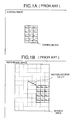
- Fig. 1A is a conceptual view for explaining a block matching method.
- Fig. 1B is a conceptual view for explaining a block matching method.
- Fig. 2A is a conceptual view for explaining a field-unit block-matching method.
- Fig. 2B is a conceptual view for explaining a field-unit block-matching method.
- Fig. 3 shows a conventional sub-sampling pattern.
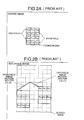
- Fig. 4A is view for explaining how to process a block-end pixel value with a two-dimensional filter.
- Fig. 4B is view for explaining how to process a block-end pixel value with a two-dimensional filter.
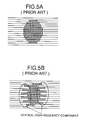
- Fig. 5A is a view for explaining vertical high-frequency components resulted from interlaced scanning.
- Fig. 5B is a view for explaining vertical high-frequency components resulted from interlaced scanning.
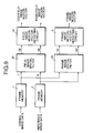
- Fig. 6 is a block-diagram of a motion-vector detecting device according to one aspect of the present invention.
- Fig. 7 is a block-diagram of a motion-vector detecting device according to another aspect of the present invention.
- Fig. 8 is a block-diagram of a motion-vector detecting device according to another aspect of the present invention.
- Fig. 9 is a block-diagram of a motion-vector detecting device according to another aspect of the present invention.
- Fig. 10 is a block-diagram of a motion-vector detecting device according to another aspect of the present invention.
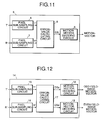
- Fig. 11 is a block-diagram of a frame motion-vector detecting circuit for detecting frame motion-vectors.
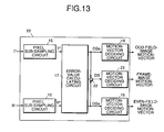
- Fig. 12 is a block-diagram of a field motion-vector detecting circuit for detecting field motion-vectors.
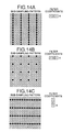
- Fig. 13 is a block-diagram of a total circuit composed of the circuits of Figs. 11 and 12 for detecting frame/frame motion-vectors.
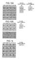
- Fig. 14A is an exemplified pixel sub-sampling pattern and filter coefficients used in the embodiment of the present invention.
- Fig. 14B is an exemplified pixel sub-sampling pattern and filter coefficients used in the embodiment of the present invention.
- Fig. 14C is an exemplified pixel sub-sampling pattern and filter coefficients used in the embodiment of the present invention.
- Fig. 15A is an exemplified pixel sub-sampling pattern and filter coefficients used in the embodiment of the present invention.
- Fig. 15B is an exemplified pixel sub-sampling pattern and filter coefficients used in the embodiment of the present invention.
- Fig. 16 is a first example of a pixel sub-sampling pattern with filter coefficients used in the embodiment of the present invention.
- Fig. 17 is a second example of a pixel sub-sampling pattern with filter coefficients used in the embodiment of the present invention.
- Fig. 18A is view for explaining how to process a block-end pixel value with a one-dimensional filter.
- Fig. 18B is view for explaining how to process a block-end pixel value with a one-dimensional filter.
- an interframe coding system using a motion-compensated prediction technique such as MPEG-1 (ISO/IEC11172) and MPEG-2 (ISO/IEC13818) has been increasingly applied in the fields of data storage, communication and broadcast.
- the system conducts motion-compensated prediction in such a manner that each image in a video sequence is divided into blocks to be coded (coding blocks) and predicted blocks are determined for each coding block by applying a detected motion-vector to a reference image.
- a difference (prediction-error) value between a coding block and each prospective prediction candidate-block in a motion-vector searching area is first calculated and a prospective block having a smallest error value is selected as a prediction block.
- a relative shift value of the prediction block position from the coding block is determined as a motion-vector.
- the block matching usually defines a prediction-error D i,j as a total of absolute values of difference between a pixel in a coding block and a pixel in a prospective prediction candidate-block, which has the following expression (1).
- a motion-vector is defined as a value (i,j) which makes the value D i,j be smallest.
- the expression (1) presumes that a block has a size of M ⁇ N and a searching area thereof has a horizontal size of [-K:K-1] and a vertical size of [-L:L-1].
- T represents a pixel value of the coding block and R represents a pixel value of the searching area.
- the equation (1) requires M ⁇ N times calculations of absolute values of the differences and M ⁇ N-1 times additions.
- a coding block on an interlaced image is decomposed into fields which motion-vectors are detected for further motion-compensated prediction for respective fields.
- a prediction-error value for motion-vectors of odd-field components of the coding block (hereinafter called “an odd-field motion-vector") and a prediction-error value for motion-vectors of even-field components of the coding block (hereinafter called “an even-field motion-vector.”) are determined by the following equations (2) and (3) respectively.
- T m,2r represents a pixel of the odd field of the coding block but a value R m+i,2r+j may be a pixel of either odd field or even field depending on a value of j.
- T m,2r+1 represents a pixel of the odd field of the coding block but a value R m+i,2+1+j may be a pixel of either even field or odd field depending on a value of j.
- T 0,0 ,T 1,0 ,T 2,0 ,T 0,2 ,T 1,2 ,T 2,2 are pixels of the odd field of the coding block and T 0,1 ,T 1,1 ,T 2,1 ,T 0,3 ,T 1,3 , T 2,3 are pixels of the even field of the coding block.
- an odd-field motion-vector (i, j) is equal to (+2,+1) and an even-field motion-vector (i, j) is equal to (-3, +2).
- Fig. 1B shows a frame-motion-vector that is so called in contrast to the field-motion vector shown in Fig. 2B.
- a so-called “full search method” is known as a most accurate motion-vector detecting method that is introduced in the above document.
- the full search method calculates prediction-error values of each of all the prediction candidates-blocks existing in a motion-vector search area by comparing with a coding block. Namely, a value of D i,j expressed by Equation (1) is calculated for each of all the combinations of (i, j) within the ranges of -K ⁇ i ⁇ K and -L ⁇ j ⁇ L.
- the document also describes a sub-sampling technique that is known as a method for effectively reducing the huge number of the above-mentioned operations.
- This method reduces the amount of pixels in each coding block to a certain pattern by sub-sampling pixels therein and performs calculations on only the restricted number of pixels.
- an error value necessary for detecting a motion-vector for a frame is equal to DS i,j according to Equation (4).
- 15 ⁇ (M/4) ⁇ (N/4) ⁇ operations for determining a sum of the difference values for each of the prediction candidates-block.
- the subsampling method can substantially reduce the number of operations as compared to the full search method (according to Equation (1)).
- the subsampling method reduces by sub-sampling the number of pixels to be calculated for error-value, it treats the same number of prediction candidate-blocks that the full search method does. Namely, the subsampling method differs from the hierarchical search method which reduces the amount of calculation by reducing the number of prediction candidate-blocks as described in the cited reference.
- the accuracy of error calculation may decrease due to sub-sampled pixels used for calculation, resulting in the decrease of the accuracy of produced motion-vectors.
- an image containing a large amount of fine texture has many high-frequency components and can therefore suffer a considerable decrease of the high-frequency component detection accuracy.
- a motion-vector detecting device which processes each coding block and a prediction candidate-block first with a two-dimensional low-pass filter device and then by sub-sampling pixels in both blocks and finally calculates an error value (Japanese Laid-open Patent Publication (TOKKAI HEI) No. 2-274083 ⁇ (motion-vector detecting device) ⁇ ).
- Japanese Laid-open Patent Publication (TOKKAI HEI) No. 2-274083 discloses the case of using, as a spatial filter, a two-dimensional low-pass filter that can be expressed by the following transfer function: Z -1 W -1 (2+Z 1 +Z -1 )(2+W 1 +W -1 )/4
- Z is a delay operator in a horizontal direction and W is a delay operator in a vertical direction.
- a sub-sampling pattern is disclosed as shown in Fig. 3.
- Figs. 4A and 4B show an example of alias-processing of a pixel value at a block-boundary.
- Fig. 4A illustrates a top-left corner of a block where a pixel (black circle) to be processed with a filter is shown together with adjacent pixels.
- two-dimensional filter having a tap of 3 ⁇ 3 can be applied to the top-left corner pixel requires pixel data in an area enclosed by a broken line.
- alias-processing In a two-dimensional filter device, it is necessary to do alias-processing for a pixel value at each block end while making the pixel value delayed in horizontal and vertical directions. To do the alias-processing, the filter device has to perform complicated address control for reading necessary pixel data from a memory. This necessarily increases the circuit of the filter device.
- a motion area of an interlaced image contains vertical high-frequency components produced by interlaced scanning, which has no relation with motion of a subject.
- Figs. 5A and 5B illustrates an example of vertically directed high-frequency components produced from interlaced scanning.
- Fig. 5A shows a still state of a subject in an image
- Fig. 5B shows the state when the subject of Fig. 5A moved in a horizontal direction.
- areas enclosed each by an oval contain high-frequency components produced in a vertical direction. These components may cause the motion-vector detecting device to detect erroneous motion-vectors because of influence of the high-frequency components to pixel values after filter processing.
- Japanese Laid-open Patent Publication (TOKKAI HEI) No. 2-274083 cannot detect field motion-vectors because of lacking in concept of using a field image.
- Fig. 6 is a block diagram of an embodiment of the present invention.
- this embodiment comprises a coding image frame memory 1 for storing pixels of a coding block, a reference image frame memory 2 for storing pixels in a motion-vector searching area, one-dimensional spatial filters 3, 4 and a motion-vector detecting circuit 5 for detecting a motion-vector for each block through calculation of matching error values using a part of pixels in the block.
- the frame memory 1 holds data of pixels in a coding image frame and the frame memory 2 holds data of pixels in a reference image frame.
- the pixel data T m,n of the coding block is output from the frame memory 1 and enters the one-dimensional spatial filter 3 through which a coding block T' having a restricted spatial frequency band of the input block is then output.
- a pixel value R m+i,n+j of a prediction candidate-block which corresponds to a motion-vector (i,j) is output from the reference frame-image memory 2 and enters the one-dimensional spatial filter 4 by which it is restricted in the same band as the coding block T and output as a band-restricted prediction candidate-block R'.
- the motion-vector detecting circuit 5 calculates a matching error between the band-restricted coding block and the band-restricted prediction candidate-block by using a part of the pixel data T' and a part of the pixel data R'.
- the motion-vector detecting circuit 5 detects a prospective prediction candidate-block having a least error value and outputs information (i,j) of the detected block.
- Fig. 11 is a block-diagram of the motion-vector detecting circuit 5 of Fig. 6.
- This circuit includes pixel sub-sampling circuits 6, 7, an error-value calculating circuit 8 for determining a block matching error between blocks by using sub-sampled pixel data and a motion-vector deciding circuit 9 for determining a motion-vector by detecting a least matching error value.
- the block pixel data T' and R' is input to the sub-sampling circuits 6 and 7 respectively, which output blocks T" and R" sub-sampled according to a specified pattern.
- the error-value calculating circuit 8 determines a matching error-value between two sub-sampled blocks T" and R" and outputs the determined error value DS i,j .
- the motion-vector deciding circuit 9 detects the least of error values DS i,j determined varying the variable (i,j) and outputs a motion-vector which is a value (i,j) corresponding to the detected least-error value DS i,j .
- black circles are pixels to be used for calculating a matching error-value and white circles are pixels to be thinned out.
- pixels are sub-sampled to 1/4 in horizontal rows only by horizontally applying a one-dimensional three-tapped FIR low-pass filter of [1, 2, 1]/4 as a spatial filter.
- a matching error-value DS i,j to be determined by using the subsampling method can be expressed according to following equation (8):
- Equation (8) T' and R' are determined by Equations (6) and (7) respectively.
- the matching error-value calculating operation is carried out on all combinations (i,j) and a combination (i,j) whose error-value DS i,j is the least of the determined error-values. This is a motion-vector that is then output from the motion-vector deciding circuit 9 of Fig. 11.
- pixels are sub-sampled to 1/4 in horizontal and vertical directions by horizontally applying a one-dimensional three-tapped FIR low-pass filter of [1, 2, 1]/4 as a spatial filter.
- a matching error-value DS i,j to be determined by using the subsampling method can be expressed according to following equation (9):
- T' and R' are determined by Equations (6) and (7) respectively.
- pixels are sub-sampled in horizontal and vertical directions in the case of Fig. 14B, a considerable effect can be obtained by applying the one-dimensional spatial filter in a horizontal direction only. A similar effect can be also obtained by applying the one-dimensional filter in a vertical direction only.
- pixels are sub-sampled to 1/4 in vertical direction by vertically applying a one-dimensional three-tapped FIR low-pass filter of [1, 2, 1]/4 as a spatial filter.
- a matching error-value DS i,j to be determined by using the subsampling method can be expressed according to following equation (12):
- Equation (12) T' and R' are determined by Equations (10) and (11) respectively.
- Figs. 18A and 18B depict how to alias-process pixels at a block end when horizontally applying a one-dimensional filter.
- Fig. 18A there is shown a pixel existing in the upper left corner of a block and an adjacent pixel.
- Fig. 18B depicts the pixel alias-processing when using a three-tapped one-dimensional filter.
- a black circle is a pixel to be processed with the filter and a rectangle drawn by a broken line designates adjacent pixels necessary for processing with the filter.
- Fig. 18B like patterned pixels have the same pixel value.
- the one-dimensional filter requires delaying pixel values in a horizontal or vertical direction only, so pixels at block ends may be alias-processed in a horizontal or vertical direction only. Namely, a filter circuit with a one-dimensional filter may be considerably simplified as compared with that with a two-dimensional filter.
- the pixels (shown by black circles) to be used for calculation of block-matching errors are set inside the block boundary not less than the number of pixels (1 in the shown cases) that are round off after a decimal point corresponding to one half of the number of the filter taps of the filter.
- Fig. 7 shows a block diagram of another embodiment of the present invention.
- This motion-vector detecting device comprises field-based (field-image-based) spatial filters 10 and 11 that are applied to the field-based coding blocks and field-based prediction candidate-blocks respectively, frame-based (frame-image-based) spatial filters 12 and 13 that are applied to the frame-based coding blocks and the frame-based prediction candidate-blocks respectively, a field-base motion-vector detecting circuit 14 for detecting an odd-field-based motion-vector and even-field-based motion-vector by determining an error between a part of plural pixels of the field-based band-limited coding block and a part of plural pixels of the field-based band-limited prediction candidate-block and a frame-based motion-vector detecting circuit 5 for detecting a frame-based motion-vector by determining an error between a part of plural pixels of the frame-based band-limited coding block and a part of plural pixels of the frame-based band-limited prediction candidate-block.
- black circles are pixels to be used for determining a matching error-value
- white circles are pixels of odd-fields
- hatched circles are pixels of even-fields.
- a two-dimensional spatial filter is used.
- a one-dimensional spatial filter may, of course, be used instead of the two-dimensional.
- pixels T m,n of a coding block on frame-by-frame basis are read out from the frame memory 1 and inputted to the field-based spatial filters 10 arid the frame-based spatial filter 12.
- the field-based spatial filter 10 possesses filter coefficients (A) shown in Fig. 15A and the frame-based spatial filter 12 possesses filter coefficients (B) shown in Fig. 15A.
- the coefficient values in the second row and the fourth row are all zeros. This is the same that respective filter coefficients (C) are applied to respective odd-field and even-field into which the coding block is decomposed as shown in Fig. 15B.
- the filter coefficients for the second and fourth rows may be set at a value other than zero, but the coding block, however, cannot be decomposed into the fields as shown in Fig. 15B.
- Pixel data of the band-limited coding block, which is processed with filter coefficients (A) shown in Fig. 15A, can be expressed according to Equation (13) while pixel data of the band-limited coding block, which is processed with filter coefficients (B) shown in Fig. 15A, can be expressed according to Equation (14).
- Tfi' m,n (T m-1,n-2 +T m,n-2 +T m+1,n-2 +T m-1,n +2T m,n +T m+1,n +T m-1,n+2 +T m,n+2 +T m+1,n+2 )/10
- Tfr' m,n (T m-1,n-1 +T m,n-1 +T m+1,n-1 +T m-1,n +2T m,n +T m+1,n +T m-1,n+1 +T m+1,n+1 )/10
- pixel data of a prediction candidate-block is read from the frame memory 2 and transferred to the field-based spatial filter 11 and the frame-based spatial filter 13 for restricting the frequency band of the block in Fig. 7.
- the pixel data of the band-limited prediction candidate-block, which is processed with filter coefficients (A) shown in Fig. 15A, can be expressed according to Equation (15) while pixel data of the band-limited prediction candidate-block, which is processed with filter coefficients (B) shown in Fig. 15A, can be expressed according to Equation (16).
- Rfi' m+i,n+j (R m+i-1,n+j-2 +R m+i,n+j-2 +R m+i+1,n+j-2 + R m+i-1,n+j +2R m+i,n+j + R m+i+1,n+j +R m+i-1,n+j+2 + R m+i,n+j+2 +R m+i+1,n+j+2 )/10
- Rfr' m+i,n+j (R m+i-1,n+j-1 +R m+i,n+j-1 +R m+i+1,n+j-1 + R m+i-1,n+j +2R m+i,n+j + R m+i+1,n+j +R m+i-1,n+j+1 + R m+i,n+j+1 +R m+i+1,n+j+1 )/10
- the pixel data of the band-limited coding block through the spatial filter and the pixel data of the band-limited prediction candidate-block through the spatial filter are inputted to the field-based motion-vector detecting circuit 14 (Fig. 7) and frame-based motion-vector detecting circuit 5 (Fig. 7) respectively.
- Field-based motion-vectors and frame-based motion-vectors are detected respectively.
- the pixel data (Equation (13)) of the band-limited field-based coding block and the pixel data (Equation (15)) of the band-limited frame-based prediction candidate-block are sub-sampled to the pattern shown in Fig. 15A by the sub-sampling circuits 15 and 16 respectively.
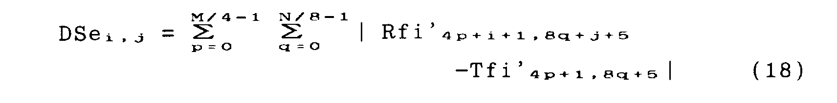
- Matching error-values DSo i,j for odd-field pixels of the coding block and matching error-values DSe i,j for even-field pixels of the coding block are determined by the error-value calculating circuit 17.
- the error-values DSo i,j and DSe i,j are represented by Equations (17) and (18) respectively.
- subscript 4p means that pixels in a block are sub-sampled to 1/4 and in a horizontal direction
- subscript 8q means that pixels in a block are sub-sampled to 1/4 for the same fields in a vertical direction as shown in Fig. 15B, resulting in vertical sub-sampling of pixels to 1/8 for a frame as shown in Fig. 15A.
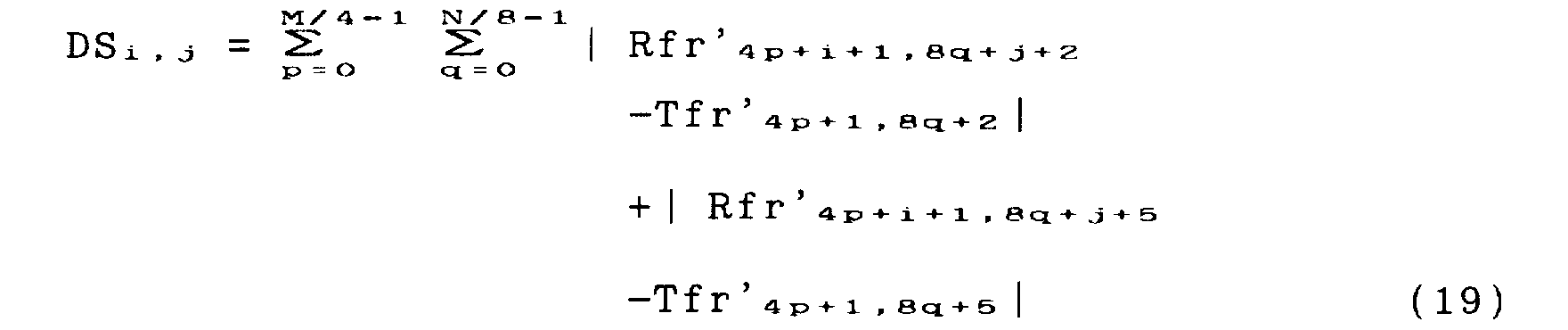
- pixel data of a frame-based band-limited coding block and pixel data of a frame-based band-limited prediction candidate-block are sub-sampled to the pattern shown in Fig. 15A by the pixel sub-sampling circuits 6 and 7 respectively, then a matching error-value DS i,j for the frame-based coding block is determined by the error-value calculating circuit 8.
- the error-value DS i,j is expressed by the following equation (19):
- the filter is applied to a frame when detecting a frame-based motion-vector while the filter is applied to a field image when detecting a field-based motion-vector.
- motion-vectors can be detected at high accuracy even for an interlaced image owing to application of a filter adapted to a base unit for which a motion-vector is detected.
- pixels (black circles) to be used for determining an error-value in Figs. 15A and 15B are disposed in the same way as those shown in Figs. 14A, 14B and 14C to eliminate the need to alias-process pixels at the block ends.
- Fig. 8 is a block diagram of another embodiment of the present invention.
- numeral 20 denotes a spatial filter applied to a coding block
- numeral 21 denotes a spatial filter applied to a prediction candidate-block.
- Components similar in function to those shown in Figs. 6 and 7 are given the same numerals.
- the embodiment of Fig. 8 differs from the embodiment of Fig. 7 only by using a common filter for fields and frame while the embodiment of Fig. 7 uses two separate spatial filters for field-based and frame-based. Accordingly, the operation of the embodiment of Fig. 8 is the same as that of the embodiment of Fig. 7.
- black circles are pixels to be used for determining matching error-values
- white circles are odd-field pixels
- hatched circles are even-field pixels.
- a horizontal one-dimensional filter is applied in the case of Fig. 16.
- the application of a vertical spatial filter to a frame including a motion area shown in Fig. 5B may cause odd lines and even lines to be mixed together, resulting in decrease in motion-vector detection accuracy.
- the horizontal spatial filter shown in Fig. 16 is applied allowing vertical high-frequency components to pass therethrough. By doing so, the field motion-vector detecting accuracy is improved.
- the one-dimensional filter is effective to use in common for a field image and a frame image.
- black circles are pixels to be used for determining matching error-values
- white circles are odd-field pixels
- hatched circles are even-field pixels.
- a two-dimensional filter is applied, which has a wider pass-band in a vertical direction than in a horizontal direction.
- the filter allows the most part of vertical high-frequency components produced in a motion area of an interlaced image to pass therethrough. Therefore, this filter can reduce the influence of mixture of odd-lines and even-lines in the interlaced image, realizing effective function of spatial filtering both a motion area and a still area.
- the filter assures high accuracy of detection of motion-vectors.
- the embodiment shown in Fig. 17 is such that it keeps effectiveness of the one-dimensional filter applied in the embodiment of Fig. 16 and provides an adequate limitation of the band in the vertical direction to improve the detection accuracy of frame motion-vectors.
- a field-based two-dimensional filter having coefficients (A) shown in Fig. 15A, which can also reduce the influence of the vertical high-frequency components produced in the interlaced image to pixel values obtained through the filter.
- Figs. 16 and 17 pixels (black circles) to be used for determining error-values are arranged in the same manner as shown in Figs. 14A, 14B and 14C eliminating the need to fold pixels at the block boundary.
- the field-based motion-vector detecting circuit 14 of Fig. 12 and the frame-based motion-vector detecting circuit 5 of Fig. 11 can be integrated in a frame/field-based motion-vector detecting circuit shown in Fig. 13. Namely, the circuit of Fig. 13 can simultaneously detect an odd-field motion-vector, an even-field motion-vector and a frame motion-vector.
- numeral 22 designates an adder for determining an error-value DS i,j for a frame motion-vector by adding an error-value DSo i,j for an odd-field motion-vector to an error-value DSe i,j for an even-field motion-vector and numeral 23 designates a motion-vector deciding circuit for detecting a smallest error-value DS i,j for frame motion-vectors.
- Components similar in function to those shown in Fig. 12 are given the same reference numerals.
- pixel data of a prediction candidate-block for an odd-field motion-vector (i,j) and pixel data of a prediction candidate-block for an even-field motion-vector (i,j) compose pixel data of a prediction candidate-block for a frame motion-vector (i,j).
- the error-value DS i,j for a frame motion-vector can be determined by adding together error-values DSo i,j and DSe i,j determined by the error-value calculating circuit of the field motion-vector detecting circuit for an odd-field motion-vector and an even-field motion-vector respectively.
- a frame motion-vector can be detected.
- Fig. 9 is a block diagram of another embodiment of the present invention.
- numeral 24 denotes a spatial filter applied to a field-based block and numeral 25 denotes a spatial filter applied to a frame-based block.
- pixel values Tfi', Tfr' of a band-limited coding block do not depend upon a value (i,j). Therefore, the coding block is processed by the filter circuit before calculating an error-value.
- the obtained pixel values Tfi', Tfr' are held in the motion-vector detecting circuit. By doing so, the need for further filtering pixel values T when calculating error-values by changing a variable (i,j). This makes it possible to use a spatial filter in common for the coding block and the prediction candidate-block, realizing the further saving in size of the circuit.
- the spatial filters 10 and 11 of Fig. 7 are integrated into the spatial filter 24 while the spatial filters 12 and 13 are integrated into the spatial filter 25.
- Fig. 10 is a block diagram of another embodiment of the present invention.
- numeral 26 denotes a spatial filter applied to all pixels to be used for error-value calculation.
- the embodiment of Fig. 10 also uses a spatial filter used in common for coding blocks and prediction candidate-block, thus simplifying its circuitry.
- the spatial filters 20 and 21 are integrated into the spatial filter 26.
- spatial filters having different characteristics are used for processing a coding block and for processing a prediction candidate-block or one of them is one-dimensional and the other is two-dimensional.
- the present invention brings the following advantageous effects:
Landscapes
- Engineering & Computer Science (AREA)
- Multimedia (AREA)
- Signal Processing (AREA)
- Compression Or Coding Systems Of Tv Signals (AREA)
Abstract
Description


Claims (9)
- A motion-vector detecting device for detecting a match between a coding block on a coding image and a prediction candidate-block on a reference image in a motion-vector searching area of the reference image, comprising an one-dimensional spatial filter (3) applied to the coding block, an one-dimensional spatial filter (4) applied to the prediction candidate-block, a motion-vector detecting circuit (5) for detecting a motion-vector by calculating differences between a part of pixels on the coding block and prediction candidate-block, characterized in that one-dimensional spatial filters (3, 4) are used for limiting bands to the coding block and the prediction candidate-block in vertical or horizontal direction and a motion-vector is detected by calculating matching errors between the part of pixels on the band-limited coding block and the band-limited prediction candidate-block.
- A motion-vector detecting device for detecting a field-based motion-vector by searching a match between a field-based coding block on an interlaced coding image and a field-based candidate-block on an interlaced reference image, detecting a frame-based motion-vector by searching a match between a frame-based coding block on an interlaced coding image and a frame-based prediction candidate-block on an interlaced reference image and adaptively selecting either the field-based motion-vector or the frame-based motion-vector, comprising a first field-based spatial filter (10) applied to the field-based coding blocks, a second field-based spatial filter (11) applied to the field-based prediction candidate-blocks of a field-image to be matched with the field-based coding block, a field-based motion-vector detecting circuit (14) for detecting a field-based motion-vector by calculating an error between a part of pixels on the field-based coding block and a part of pixels on a field-based prediction candidate-block, a first frame-based spatial filter (12) applied to the frame-based coding blocks, a second frame-based spatial filter (13) applied to frame-based prediction candidate-blocks of a frame-image to be matched with the frame-based coding block, a frame-based motion-vector detecting circuit (5) for detecting a frame-based motion-vector by calculating an error between the part of pixels on the frame-based coding block and the part of pixels on the frame-based prediction candidate-block, wherein a field-based motion-vector and a frame-based motion-vector are detected by respective different filters with different band limitations of a field image and a frame image and by calculating a matching error between the part of pixels on the band-limited coding block and the part of pixels on the band-limited prediction candidate-block for each of the field-based image and the frame-based image.
- A motion-vector detecting device as defined in claim 2, characterized in that the first field-based spatial filter (10) and the first frame-based spatial filter (12) are identical with each other and the second field-based spatial-filter (11) and the second frame-based spatial-filter (13) are identical with each other.
- A motion-vector detecting device as defined in claim 2, characterized in that the first field-based spatial filter (10) and the second field-based spatial-filter (11) are identical with each other and the first frame-based spatial-filter (12) and the second frame-based spatial-filter (13) are identical with each other.
- A motion-vector detecting device as defined in claim 2, characterized in that all the first and second field-based spatial-filters (10, 11) and the first and second frame-based spatial-filters (12, 13) are identical.
- A motion-vector detecting device as defined in any one of claims 2 to 4, characterized in that each of the spatial filters (10, 11, 12, 13) is a one-dimensional low-pass filter.
- A motion-vector detecting device as defined in any one of claims 2 to 4, characterized in that each of the spatial filters (10, 11, 12, 13) is a two-dimensional low-pass filter.
- A motion-vector detecting device as defined in any one of claims 1 to 7, characterized in that a part of the spatial filters (3, 4, 10, 11, 12, 13) is one-dimensional and a remaining part is two-dimensional.
- A motion-vector detecting device as defined in any one of claims 1 to 8, characterized in that in calculating error-values for a group of pixels by the motion-vector detecting circuit (5, 14), block-end pixels are considered to exist inside the block boundary by the number of pixels rounded off after a decimal point corresponding to one half of the number of taps of the spatial filters.
Applications Claiming Priority (3)
| Application Number | Priority Date | Filing Date | Title |
|---|---|---|---|
| JP14376197 | 1997-06-02 | ||
| JP14376197A JPH10336668A (en) | 1997-06-02 | 1997-06-02 | Motion vector detection device |
| JP143761/97 | 1997-06-02 |
Publications (2)
| Publication Number | Publication Date |
|---|---|
| EP0883301A2 true EP0883301A2 (en) | 1998-12-09 |
| EP0883301A3 EP0883301A3 (en) | 2001-01-31 |
Family
ID=15346416
Family Applications (1)
| Application Number | Title | Priority Date | Filing Date |
|---|---|---|---|
| EP19980304350 Ceased EP0883301A3 (en) | 1997-06-02 | 1998-06-02 | Motion-vector detecting device |
Country Status (3)
| Country | Link |
|---|---|
| US (1) | US6343100B1 (en) |
| EP (1) | EP0883301A3 (en) |
| JP (1) | JPH10336668A (en) |
Cited By (3)
| Publication number | Priority date | Publication date | Assignee | Title |
|---|---|---|---|---|
| WO1999040726A3 (en) * | 1998-02-06 | 1999-10-07 | Koninkl Philips Electronics Nv | Motion or depth estimation |
| DE10221172A1 (en) * | 2002-05-13 | 2003-12-04 | Voith Paper Patent Gmbh | Elastic smoothing roller and method for producing such |
| WO2016144443A1 (en) * | 2015-03-06 | 2016-09-15 | Qualcomm Incorporated | Method and apparatus for low complexity quarter pel generation in motion search |
Families Citing this family (23)
| Publication number | Priority date | Publication date | Assignee | Title |
|---|---|---|---|---|
| JP4496595B2 (en) * | 1999-03-29 | 2010-07-07 | ソニー株式会社 | Image processing apparatus, image processing method, and recording medium |
| US6560286B1 (en) * | 1999-12-29 | 2003-05-06 | Intel Corporation | Field frame motion design for digital video decoder |
| WO2001086820A1 (en) * | 2000-05-09 | 2001-11-15 | Sony Corporation | Data processing device and data processing method, and recorded medium |
| US7116372B2 (en) * | 2000-10-20 | 2006-10-03 | Matsushita Electric Industrial Co., Ltd. | Method and apparatus for deinterlacing |
| US7095787B2 (en) | 2001-11-29 | 2006-08-22 | Matsushita Electric Industrial Co., Ltd. | Coding distortion removal method, moving picture coding method, moving picture decoding method, and apparatus for realizing the same, program |
| EP2938071B1 (en) * | 2001-11-29 | 2017-11-15 | Godo Kaisha IP Bridge 1 | Coding distortion removal method |
| CN1279755C (en) * | 2003-04-16 | 2006-10-11 | 华亚微电子(上海)有限公司 | Method of interleave and line by line conversion of mixing two dimensional and three dimensional |
| KR100994771B1 (en) * | 2003-12-29 | 2010-11-16 | 삼성전자주식회사 | Motion vector search method and search device using block matching |
| KR20050119285A (en) * | 2004-06-16 | 2005-12-21 | 삼성전자주식회사 | Apparatus and method for hybrid block-based motion estimation |
| US20050286777A1 (en) * | 2004-06-27 | 2005-12-29 | Roger Kumar | Encoding and decoding images |
| US7705884B2 (en) * | 2004-07-21 | 2010-04-27 | Zoran Corporation | Processing of video data to compensate for unintended camera motion between acquired image frames |
| JP2006279850A (en) * | 2005-03-30 | 2006-10-12 | Sanyo Electric Co Ltd | Image processing apparatus |
| US7920959B1 (en) * | 2005-05-01 | 2011-04-05 | Christopher Reed Williams | Method and apparatus for estimating the velocity vector of multiple vehicles on non-level and curved roads using a single camera |
| US8391630B2 (en) * | 2005-12-22 | 2013-03-05 | Qualcomm Mems Technologies, Inc. | System and method for power reduction when decompressing video streams for interferometric modulator displays |
| US8542278B2 (en) * | 2005-12-26 | 2013-09-24 | Kyocera Corporation | Shaking detection device, shaking correction device, imaging device, and shaking detection method |
| CN101276248B (en) * | 2007-03-27 | 2010-08-04 | 义隆电子股份有限公司 | Multi-template one-dimensional block matching method and device |
| US8422559B2 (en) * | 2007-10-10 | 2013-04-16 | Mediatek Inc. | Matching-pixel sub-sampling motion estimation method for video compression |
| WO2012036493A2 (en) * | 2010-09-17 | 2012-03-22 | (주)에스엔피월드 | Apparatus for liquid material application having an elastic support unit for supporting a rotary roller |
| KR101441899B1 (en) * | 2010-10-06 | 2014-09-25 | 에스케이텔레콤 주식회사 | Method And Apparatus for Encoding And Decoding Motion Vector |
| LT3767952T (en) | 2012-01-19 | 2022-01-10 | Electronics And Telecommunications Research Institute | Apparatus for image coding/decoding |
| US20140105305A1 (en) * | 2012-10-15 | 2014-04-17 | Vixs Systems, Inc. | Memory cache for use in video processing and methods for use therewith |
| CN116320393B (en) | 2013-01-04 | 2025-12-23 | 杜比视频压缩有限责任公司 | High-efficiency scalable coding concept |
| KR102127281B1 (en) | 2013-04-08 | 2020-06-26 | 지이 비디오 컴프레션, 엘엘씨 | Coding concept allowing efficient multi-view/layer coding |
Family Cites Families (5)
| Publication number | Priority date | Publication date | Assignee | Title |
|---|---|---|---|---|
| US5319456A (en) | 1989-10-17 | 1994-06-07 | Mitsubishi Denki Kabushiki Kaisha | Moving vector detecting apparatus |
| DE69230115T2 (en) * | 1991-05-23 | 2000-04-20 | Nippon Hoso Kyokai | Evaluation device and method used for a device for the detection of motion vectors |
| JPH06209466A (en) * | 1992-10-07 | 1994-07-26 | Canon Inc | Motion vector detector |
| US5598217A (en) | 1993-12-07 | 1997-01-28 | Matsushita Electric Industrial Co., Ltd. | Circuit for executing an interpolation processing on a sub-sampled image signal |
| JP3876392B2 (en) * | 1996-04-26 | 2007-01-31 | 富士通株式会社 | Motion vector search method |
-
1997
- 1997-06-02 JP JP14376197A patent/JPH10336668A/en active Pending
-
1998
- 1998-05-28 US US09/085,001 patent/US6343100B1/en not_active Expired - Fee Related
- 1998-06-02 EP EP19980304350 patent/EP0883301A3/en not_active Ceased
Cited By (4)
| Publication number | Priority date | Publication date | Assignee | Title |
|---|---|---|---|---|
| WO1999040726A3 (en) * | 1998-02-06 | 1999-10-07 | Koninkl Philips Electronics Nv | Motion or depth estimation |
| DE10221172A1 (en) * | 2002-05-13 | 2003-12-04 | Voith Paper Patent Gmbh | Elastic smoothing roller and method for producing such |
| WO2016144443A1 (en) * | 2015-03-06 | 2016-09-15 | Qualcomm Incorporated | Method and apparatus for low complexity quarter pel generation in motion search |
| US10291932B2 (en) | 2015-03-06 | 2019-05-14 | Qualcomm Incorporated | Method and apparatus for low complexity quarter pel generation in motion search |
Also Published As
| Publication number | Publication date |
|---|---|
| EP0883301A3 (en) | 2001-01-31 |
| JPH10336668A (en) | 1998-12-18 |
| US6343100B1 (en) | 2002-01-29 |
Similar Documents
| Publication | Publication Date | Title |
|---|---|---|
| EP0883301A2 (en) | Motion-vector detecting device | |
| US6690729B2 (en) | Motion vector search apparatus and method | |
| EP1430724B1 (en) | Motion estimation and/or compensation | |
| EP0720355B1 (en) | Apparatus for determining motion vectors through the use of an adaptive median filtering technique | |
| EP0488795B1 (en) | Motion vector detection apparatus | |
| US6327391B1 (en) | Protecting image quality from occurrence of uncorrectable errors | |
| JP3781203B2 (en) | Image signal interpolation apparatus and image signal interpolation method | |
| EP0540762B1 (en) | Method for detecting moving vector and apparatus therefor, and system for processing image signal using the apparatus | |
| US5650828A (en) | Method and apparatus for detecting and thinning a contour image of objects | |
| CA2218865A1 (en) | Hybrid hierarchical/full-search mpeg encoder motion estimation | |
| US5635994A (en) | Method of making a hierarchical estimate of image motion in a television signal | |
| US7746930B2 (en) | Motion prediction compensating device and its method | |
| EP0585051A2 (en) | Image processing method and apparatus | |
| EP1260094A2 (en) | Method and apparatus for visual lossless image syntactic encoding | |
| JPS6152084A (en) | Highly efficient encoder | |
| CA2449048A1 (en) | Methods and apparatus for sub-pixel motion estimation | |
| JP2005501442A (en) | Apparatus, image encoder and image decoder for interpolating sampling values | |
| EP0720356B1 (en) | Apparatus for determining motion vectors | |
| US6714593B1 (en) | Motion compensating prediction of moving image sequences | |
| KR20050077285A (en) | Resolution conversion method and device | |
| EP1094671A1 (en) | Method of motion estimation for a digital input video signal | |
| US20030086497A1 (en) | Motion vector detecting device improved in detection speed of motion vectors and system employing the same devices | |
| JPH1013836A (en) | Motion vector detection device | |
| JP2005348176A (en) | Image processing device | |
| Itoh | Similarity-based demosaicing algorithm using unified high-frequency map |
Legal Events
| Date | Code | Title | Description |
|---|---|---|---|
| PUAI | Public reference made under article 153(3) epc to a published international application that has entered the european phase |
Free format text: ORIGINAL CODE: 0009012 |
|
| AK | Designated contracting states |
Kind code of ref document: A2 Designated state(s): DE FR GB |
|
| AX | Request for extension of the european patent |
Free format text: AL;LT;LV;MK;RO;SI |
|
| PUAL | Search report despatched |
Free format text: ORIGINAL CODE: 0009013 |
|
| AK | Designated contracting states |
Kind code of ref document: A3 Designated state(s): AT BE CH CY DE DK ES FI FR GB GR IE IT LI LU MC NL PT SE |
|
| AX | Request for extension of the european patent |
Free format text: AL;LT;LV;MK;RO;SI |
|
| 17P | Request for examination filed |
Effective date: 20010406 |
|
| AKX | Designation fees paid |
Free format text: AT BE CH LI |
|
| RBV | Designated contracting states (corrected) |
Designated state(s): DE FR GB |
|
| STAA | Information on the status of an ep patent application or granted ep patent |
Free format text: STATUS: THE APPLICATION HAS BEEN REFUSED |
|
| 18R | Application refused |
Effective date: 20100325 |