EP0882884A2 - Fuel injection system with pressure decay metering method - Google Patents
Fuel injection system with pressure decay metering method Download PDFInfo
- Publication number
- EP0882884A2 EP0882884A2 EP98110100A EP98110100A EP0882884A2 EP 0882884 A2 EP0882884 A2 EP 0882884A2 EP 98110100 A EP98110100 A EP 98110100A EP 98110100 A EP98110100 A EP 98110100A EP 0882884 A2 EP0882884 A2 EP 0882884A2
- Authority
- EP
- European Patent Office
- Prior art keywords
- fuel
- pressure
- injector
- chamber
- engine
- Prior art date
- Legal status (The legal status is an assumption and is not a legal conclusion. Google has not performed a legal analysis and makes no representation as to the accuracy of the status listed.)
- Granted
Links
Images
Classifications
-
- F—MECHANICAL ENGINEERING; LIGHTING; HEATING; WEAPONS; BLASTING
- F02—COMBUSTION ENGINES; HOT-GAS OR COMBUSTION-PRODUCT ENGINE PLANTS
- F02M—SUPPLYING COMBUSTION ENGINES IN GENERAL WITH COMBUSTIBLE MIXTURES OR CONSTITUENTS THEREOF
- F02M37/00—Apparatus or systems for feeding liquid fuel from storage containers to carburettors or fuel-injection apparatus; Arrangements for purifying liquid fuel specially adapted for, or arranged on, internal-combustion engines
- F02M37/04—Feeding by means of driven pumps
- F02M37/046—Arrangements for driving diaphragm-type pumps
-
- F—MECHANICAL ENGINEERING; LIGHTING; HEATING; WEAPONS; BLASTING
- F02—COMBUSTION ENGINES; HOT-GAS OR COMBUSTION-PRODUCT ENGINE PLANTS
- F02D—CONTROLLING COMBUSTION ENGINES
- F02D41/00—Electrical control of supply of combustible mixture or its constituents
- F02D41/30—Controlling fuel injection
- F02D41/32—Controlling fuel injection of the low pressure type
-
- F—MECHANICAL ENGINEERING; LIGHTING; HEATING; WEAPONS; BLASTING
- F02—COMBUSTION ENGINES; HOT-GAS OR COMBUSTION-PRODUCT ENGINE PLANTS
- F02M—SUPPLYING COMBUSTION ENGINES IN GENERAL WITH COMBUSTIBLE MIXTURES OR CONSTITUENTS THEREOF
- F02M39/00—Arrangements of fuel-injection apparatus with respect to engines; Pump drives adapted to such arrangements
- F02M39/02—Arrangements of fuel-injection apparatus to facilitate the driving of pumps; Arrangements of fuel-injection pumps; Pump drives
-
- F—MECHANICAL ENGINEERING; LIGHTING; HEATING; WEAPONS; BLASTING
- F02—COMBUSTION ENGINES; HOT-GAS OR COMBUSTION-PRODUCT ENGINE PLANTS
- F02M—SUPPLYING COMBUSTION ENGINES IN GENERAL WITH COMBUSTIBLE MIXTURES OR CONSTITUENTS THEREOF
- F02M51/00—Fuel-injection apparatus characterised by being operated electrically
- F02M51/02—Fuel-injection apparatus characterised by being operated electrically specially for low-pressure fuel-injection
-
- F—MECHANICAL ENGINEERING; LIGHTING; HEATING; WEAPONS; BLASTING
- F02—COMBUSTION ENGINES; HOT-GAS OR COMBUSTION-PRODUCT ENGINE PLANTS
- F02M—SUPPLYING COMBUSTION ENGINES IN GENERAL WITH COMBUSTIBLE MIXTURES OR CONSTITUENTS THEREOF
- F02M59/00—Pumps specially adapted for fuel-injection and not provided for in groups F02M39/00 -F02M57/00, e.g. rotary cylinder-block type of pumps
- F02M59/12—Pumps specially adapted for fuel-injection and not provided for in groups F02M39/00 -F02M57/00, e.g. rotary cylinder-block type of pumps having other positive-displacement pumping elements, e.g. rotary
- F02M59/14—Pumps specially adapted for fuel-injection and not provided for in groups F02M39/00 -F02M57/00, e.g. rotary cylinder-block type of pumps having other positive-displacement pumping elements, e.g. rotary of elastic-wall type
-
- F—MECHANICAL ENGINEERING; LIGHTING; HEATING; WEAPONS; BLASTING
- F02—COMBUSTION ENGINES; HOT-GAS OR COMBUSTION-PRODUCT ENGINE PLANTS
- F02M—SUPPLYING COMBUSTION ENGINES IN GENERAL WITH COMBUSTIBLE MIXTURES OR CONSTITUENTS THEREOF
- F02M2200/00—Details of fuel-injection apparatus, not otherwise provided for
- F02M2200/40—Fuel-injection apparatus with fuel accumulators, e.g. a fuel injector having an integrated fuel accumulator
Definitions
- This invention relates to fuel delivery systems and more particularly to a fuel injection system wherein a diaphragm type fuel pump is driven by a feature in an engine's exhaust valve train, and fuel metering, through a fuel injector, is a function of a reduction of fuel pressure in an injector chamber of the fuel pump during engine fuel injection.
- this system is extremely expensive by virtue of the extensive number of components in the system, and the accuracy necessary and built into the metering components, i.e. regulator and injector; sensing components for MAP, airflow and camshaft position; and the fuel pressure supply pump.
- the metering components i.e. regulator and injector; sensing components for MAP, airflow and camshaft position; and the fuel pressure supply pump.
- the present invention provides a fuel injection system wherein injector calibration is not a factor in the metering of the system thus reducing the required accuracy of the system components and thereby the cost of such a system.
- the fuel injection system disclosed herein utilizes a diaphragm type fuel pump, where fuel metering is a function of the change in pressure in an injector chamber as fuel is injected into an engine.
- the fuel injection system is used with an engine having exhaust valve train drive means such as an exhaust cam lobe.
- the system includes a compression spring connected to the exhaust valve train drive means for compression and expansion movement.
- the system also includes a diaphragm fuel pump having a pumping chamber and an injector chamber in fuel flow communication.
- the pump diaphragm is driven by the compression spring and pumps fuel from a fuel tank, usually at a higher elevation and operating under the force of gravity, into the injector chamber.
- the pumping chamber includes a fuel inlet passage having a check valve through which fuel is received from the tank.
- the injector chamber receives fuel from the pumping chamber during compression and expansion cycling of the compression spring by the valve train drive means which moves the diaphragm.
- the injector chamber includes a spring accumulator, or other type of pressure accumulator, and connects with a fuel injector.
- a check valve is disposed between the pumping and injector chambers to prevent fuel flow back into the pumping chamber.
- a pressure sensor is mounted for sensing fuel pressure in the injector chamber and operates to communicate the fuel pressure value in the injector chamber.
- An engine controller receives the fuel pressure value of the fuel pressure in the injector chamber and controls fuel metering based upon the reduction in fuel pressure in the injector chamber during engine fuel injection. Timing means in communication with the engine controller initiates fuel injection.
- the timing means may include a crankshaft position sensor and/or a camshaft position sensor.
- the crankshaft position sensor is a crankshaft toothed wheel sensor including a magnetic pickup electrically connected to the engine controller.
- the pressure sensor is a pressure transducer that communicates a voltage proportional to pressure in the injection chamber to the engine controller.
- a throttle position sensor and engine temperature sensor are electrically connected to the engine controller.
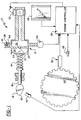
- FIG. 1 is a schematic view of a fuel injection system using a pressure decay metering method constructed in accordance with the present invention.
- numeral 10 generally indicates a fuel injection system that provides for fuel delivery based upon system pressure changes. As is hereinafter more fully described, the system 10 eliminates the necessity of fuel injector calibration.
- FIG. 1 illustrates a diaphragm type fuel pump 12 driven by a compression spring 14 connected to a push rod 16 driven by the engine's exhaust cam lobe 18.
- Fuel pump 12 includes a pumping chamber 20 having a pump diaphragm 22 driven by the compression spring 14.
- the pumping chamber 20 includes a fuel inlet passage 24 having a check valve therein.
- An injector chamber 26, in fuel flow communication with the pumping chamber 20, receives fuel from the pumping chamber during compression and expansion cycling of the compression spring 14.
- the injector chamber 26 includes an accumulator 28, and connects with a fuel injector 30.
- a check valve 32 disposed between the chambers 20,26 prevents fuel flow back into the pumping chamber.
- the exhaust valve train drive means is the exhaust cam lobe 18 although other convenient points in the exhaust valve train can also be utilized.
- the exhaust valve train drive is used since it will create a pressure pulse which will be used for fuel metering just prior to the opening of an associated intake valve, which is an appropriate time to build pressure for a subsequent injection of fuel.
- the fuel for each injection pulse is pressurized just before its corresponding injection.
- the push rod 16 drives the pump diaphragm 22 through the compression spring 14, so that an overpressure condition can be absorbed by compression of the spring, thus insuring that the injector chamber 26 is never overpressurized beyond the burst pressure of the diaphragm 22.
- the pump diaphragm 22 closes the pumping chamber 20 which is fed, optionally by gravity, from a fuel supply tank, not shown, at a higher elevation through a passage 24 equipped with a check valve to prevent fuel outflow back to the tank during the pressurization stroke.
- the pumping chamber 20 pumps fuel to the injector chamber 26, also through a check valve 32, which flows outward, but not back during the return stroke of the diaphragm 22.
- the injector chamber 26 includes accumulator 28 illustrated as a spring accumulator.
- Other accumulators such as of a piston, gas bladder, or diaphragm type construction can be utilized.
- Diaphragm 22 travels outwardly to fill the pumping chamber 20. Thereafter, an amount of fuel is delivered to the injector chamber by inward motion of the diaphragm during the motion of the cam lobe 18 causing push rod 16 movement in a pumping stroke.
- the injector 30 is kept closed.
- a pressure sensor 34 preferably a pressure transducer, which connects to the injector chamber 26, and communicates a voltage proportional to the pressure in the injector chamber 26 to an engine controller 36.
- the engine controller 36 uses this pressure information for two purposes, for fuel metering and for engine position information.
- engine position information is provided by the combination of a crankshaft toothed wheel sensor 38, for accurate crank position information, and by a camshaft position sensor 40 of less accuracy.
- the camshaft sensor 40 provides information (on a four-stroke cycle engine) as to whether the crankshaft TDC marker is indicating a compression TDC or an exhaust TDC, which are indistinguishable by the crankshaft sensor 38.
- the peak of the fuel pressure reading in the injector chamber 26 is an indication of the position of the nose 42 of the exhaust cam lobe 18, since the cam is used to drive the pump diaphragm 22.
- the second function of the pressure sensor 34 is to determine the metering rate of the injector 30. Since the accumulator 28 is of known piston area, the movement of the piston 44 is an indication of the volume of fuel entering or leaving the injector chamber 26. Entering fuel quantity is of no great interest, but fuel quantity leaving the chamber 26 is a measure of the fuel quantity being delivered to the engine. Motion of the accumulator piston 44 and compression of its spring 32 are measurable as a change in the pressure in the injector chamber 26 since the spring force divided by the accumulator piston area represents the pressure of the fuel in the chamber. This pressure change can be used to determine the amount of fuel leaving the chamber 26 during an injection of fuel into the engine.
- a pressure reading taken before the start of injection, less the pressure reading after injection equates to the volume of fuel which left the chamber 26 between readings. More frequent readings during the injection event can be integrated by the engine controller 36 to provide a running total of fuel delivered during one injection. It is then possible to initiate an injection, integrate the delivered fuel until the desired quantity is reached, and then shut off the injector 30. It has been found that a finite amount of fuel above the desired level is injected during shutoff, but this quantity is also measurable by this technique.
- Previous injections allow calculation of the flow delivered between electrical shutoff and close of the injector 30. This offset is subtracted from the desired total before it is compared to the fuel delivered at each time step during the injection. Such independence from opening and closing time considerations allow cost reduction in injector driver circuitry, since driver costs are incurred in trying to optimize injector opening and closing performance.
- injector calibration is not a factor in the metering of the system. Since the fuel quantity is measured at each step of the system, the delivery rate, either static flow, dynamic flow, or opening/closing times, is of little concern to the metering system. This translates to a large cost reduction in the injector 30 since the precision of metering orifices, needle lift, and return spring preload can be lessened, as can the testing and calibration costs associated with conventional injectors.
- the pressure regulation method utilized by system 10 is less costly than fuel delivery applications of conventional systems, since absolute pressure is not required to be accurate. And since the system 10 measures delta pressure rather than absolute levels, the actual setting is less critical. The further implications of this method is that the pressure need not be constant, and that the regulation system need not be referenced to the pressure in an intake manifold since pressure across the injector is of relatively little interest. This dependence on delta pressure also reduces the cost of a pressure transducer, since it does not have to measure absolute pressure.
- a relative (gage) pressure sensor is adequate for the system, and its offset value does not need to be calibrated in sensor manufacturing. Since delta pressures are measured, an accurate gain is required (usually inherent in sensor manufacture), but the subtraction inherent in delta pressure calculations makes offset disappear from the process. Offset is typically the quantity trimmed in the sensor calibration process.
- system 10 may include a throttle position sensor 46 and an engine temperature sensor 48 in communication with engine controller 36 providing throttle position information and engine temperature information, respectively, to the engine controller.
Abstract
Description
Claims (16)
- A fuel injection system for an engine having exhaust valve train drive means, the system comprising:a compression spring connected to said exhaust valve train drive means for compression and expansion movement therewith;a diaphragm fuel pump including:a pumping chamber having a pump diaphragm driven by said compression spring, said pumping chamber including a fuel inlet passage having a check valve therein,an injector chamber in fuel flow communication with said pumping chamber and receiving fuel from said pumping chamber during cycling of said compression spring, said injector chamber including an accumulator and being connected with a fuel injector,a check valve between said chambers preventing fuel flow back into said pumping chamber;a pressure sensor mounted for sensing fuel pressure in said injector chamber and operable to communicate the fuel pressure value in said injector chamber;an engine controller receiving said fuel pressure value in said injector chamber for controlling fuel metering based upon the reduction in fuel pressure in said injector chamber during engine fuel injection; andtiming means in communication with said engine controller for initiating fuel injection.
- The fuel injection system of claim 1 wherein said timing means a crankshaft position sensor.
- The fuel injection system of claim 2 wherein said crankshaft position sensor is a crankshaft toothed wheel sensor including a magnetic pickup electrically connected to said engine controller.
- The fuel injection system of claim 1 wherein said exhaust valve train drive means is an exhaust cam lobe.
- The fuel injection system of claim 1 wherein said timing means is a camshaft position sensor.
- The fuel injection system of claim 1 wherein said timing means uses peak pressure in the injector chamber to indicate engine timing.
- The fuel injection system of claim 1 wherein pressure sensor is a pressure transducer that communicates a voltage proportional to pressure in said injection chamber, to said engine controller.
- The fuel injection system of claim 1 including a throttle position sensor electrically connected to said engine controller.
- The fuel injection system of claim 1 including an engine temperature sensor electrically connected to said engine controller.
- A method for injecting fuel into an engine having exhaust valve train drive means, the method comprising the steps of:providing a diaphragm fuel pump driven by the valve train drive means;providing an injector chamber including an accumulator in fuel flow communication with the fuel pump for receiving fuel from the fuel pump during cycling of the engine;sensing fuel pressure in said injector chamber;communicating the fuel pressure value in the injector chamber to an engine controller; andcontrolling fuel metering based upon the reduction in fuel pressure in the injector chamber during engine fuel injection.
- The method of claim 10 comprising the step of:using peak pressure in the injector chamber to indicate engine timing and thereby initiate the fuel injection.
- The method of claim 10 comprising the step of:initiating fuel injection as a function of sensed engine cycle position.
- A method for injecting fuel into an engine comprising the steps of:providing a fuel pump operative in relation to engine cycle position;providing an accumulator in fuel flow communication with the fuel pump and an associated fuel injector;sensing fuel pressure in the accumulator;communicating the fuel pressure value in the accumulator to an engine controller; andcontrolling fuel metering based upon the reduction in fuel pressure in the accumulator during engine fuel injection.
- The method of claim 13 including the step of:monitoring pressure decay in the accumulator during fuel delivery.
- The method of claim 14 including the step of:closing of the fuel injector to cut off fuel flow upon occurrence of a predetermined value of pressure decay in the accumulator.
- The method of claim 13 including the step of:using peak pressure in the accumulator to initiate the fuel injection.
Applications Claiming Priority (2)
| Application Number | Priority Date | Filing Date | Title |
|---|---|---|---|
| US08/870,153 US5832898A (en) | 1997-06-05 | 1997-06-05 | Fuel injection system with pressure decay metering method |
| US870153 | 1997-06-05 |
Publications (3)
| Publication Number | Publication Date |
|---|---|
| EP0882884A2 true EP0882884A2 (en) | 1998-12-09 |
| EP0882884A3 EP0882884A3 (en) | 2001-11-14 |
| EP0882884B1 EP0882884B1 (en) | 2003-05-07 |
Family
ID=25354881
Family Applications (1)
| Application Number | Title | Priority Date | Filing Date |
|---|---|---|---|
| EP98110100A Expired - Lifetime EP0882884B1 (en) | 1997-06-05 | 1998-06-03 | Fuel injection system with pressure decay metering method |
Country Status (3)
| Country | Link |
|---|---|
| US (1) | US5832898A (en) |
| EP (1) | EP0882884B1 (en) |
| DE (1) | DE69814231T2 (en) |
Families Citing this family (3)
| Publication number | Priority date | Publication date | Assignee | Title |
|---|---|---|---|---|
| US7448361B1 (en) | 2007-10-23 | 2008-11-11 | Ford Global Technologies, Llc | Direct injection fuel system utilizing water hammer effect |
| US7966984B2 (en) * | 2007-10-26 | 2011-06-28 | Ford Global Technologies, Llc | Direct injection fuel system with reservoir |
| JP5195451B2 (en) * | 2008-04-15 | 2013-05-08 | 株式会社デンソー | FUEL INJECTION DEVICE AND PRESSURE ACCUMULATION FUEL INJECTION SYSTEM USED FOR THE SAME |
Citations (3)
| Publication number | Priority date | Publication date | Assignee | Title |
|---|---|---|---|---|
| US4718384A (en) * | 1985-05-29 | 1988-01-12 | Toyota Jidosha Kabushiki Kaisha | Fuel injector for use in an internal combustion engine |
| EP0459429A1 (en) * | 1990-05-29 | 1991-12-04 | Toyota Jidosha Kabushiki Kaisha | Fuel injector |
| EP0691471A1 (en) * | 1994-07-08 | 1996-01-10 | Mitsubishi Jidosha Kogyo Kabushiki Kaisha | Pressure storage fuel injection system |
Family Cites Families (11)
| Publication number | Priority date | Publication date | Assignee | Title |
|---|---|---|---|---|
| US2055578A (en) * | 1930-05-29 | 1936-09-29 | Bosch Robert | Fuel supply and regulating system for internal combustion engines |
| US4100904A (en) * | 1973-09-28 | 1978-07-18 | Robert Bosch Gmbh | Fuel injection system |
| US4419977A (en) * | 1979-03-23 | 1983-12-13 | Eaton Corporation | Fuel injection system and timing advance device therefor |
| DE3327399A1 (en) * | 1983-07-29 | 1985-02-21 | Robert Bosch Gmbh, 7000 Stuttgart | PUMPEDUESE FOR FUEL INJECTION IN INTERNAL COMBUSTION ENGINES |
| JPS61160565A (en) * | 1985-01-04 | 1986-07-21 | Seiko Epson Corp | Fuel injection device |
| JP2580367B2 (en) * | 1990-06-11 | 1997-02-12 | 本田技研工業株式会社 | Electronically controlled fuel injector for internal combustion engines |
| KR100207976B1 (en) * | 1991-05-15 | 1999-07-15 | 톰 바스코비치 | Fuel system for a fuel injected engine |
| US5257606A (en) * | 1992-06-23 | 1993-11-02 | Carter Automotive Company, Inc. | Fuel pump accumulator |
| US5323750A (en) * | 1993-08-25 | 1994-06-28 | Kohler Co. | Integral engine valve cover and fuel pump |
| DE4414242A1 (en) * | 1994-04-23 | 1995-10-26 | Bosch Gmbh Robert | Fuel injection device for internal combustion engines |
| JPH09209867A (en) * | 1996-02-07 | 1997-08-12 | Mitsubishi Motors Corp | Fuel injector |
-
1997
- 1997-06-05 US US08/870,153 patent/US5832898A/en not_active Expired - Fee Related
-
1998
- 1998-06-03 DE DE69814231T patent/DE69814231T2/en not_active Expired - Fee Related
- 1998-06-03 EP EP98110100A patent/EP0882884B1/en not_active Expired - Lifetime
Patent Citations (3)
| Publication number | Priority date | Publication date | Assignee | Title |
|---|---|---|---|---|
| US4718384A (en) * | 1985-05-29 | 1988-01-12 | Toyota Jidosha Kabushiki Kaisha | Fuel injector for use in an internal combustion engine |
| EP0459429A1 (en) * | 1990-05-29 | 1991-12-04 | Toyota Jidosha Kabushiki Kaisha | Fuel injector |
| EP0691471A1 (en) * | 1994-07-08 | 1996-01-10 | Mitsubishi Jidosha Kogyo Kabushiki Kaisha | Pressure storage fuel injection system |
Also Published As
| Publication number | Publication date |
|---|---|
| US5832898A (en) | 1998-11-10 |
| DE69814231T2 (en) | 2004-04-08 |
| EP0882884B1 (en) | 2003-05-07 |
| EP0882884A3 (en) | 2001-11-14 |
| DE69814231D1 (en) | 2003-06-12 |
Similar Documents
| Publication | Publication Date | Title |
|---|---|---|
| US7000600B1 (en) | Fuel injection control apparatus for internal combustion engine | |
| EP0900325B1 (en) | Fuel leakage detector system | |
| US6557530B1 (en) | Fuel control system including adaptive injected fuel quantity estimation | |
| JP3796912B2 (en) | Fuel injection device for internal combustion engine | |
| US4788960A (en) | Solenoid-valve-controlled fuel injection device | |
| US7255087B2 (en) | Method for controlling an injection system of an internal combustion engine | |
| US8459234B2 (en) | Fuel injection device, fuel injection system, and method for determining malfunction of the same | |
| JP4501975B2 (en) | FUEL INJECTION DEVICE AND METHOD FOR MANUFACTURING FUEL INJECTION DEVICE | |
| US9127612B2 (en) | Fuel-injection-characteristics learning apparatus | |
| US7520265B2 (en) | Fuel injection controller | |
| JPH1089090A (en) | Hydraulic actuation type electronic controlled fuel injection device, oil viscosity measuring device, and oil viscosity measuring method | |
| US7905136B2 (en) | Method of operating a fuel injector | |
| JPH109033A (en) | Fuel injection device of internal combustion engine | |
| JP4158501B2 (en) | Accumulated fuel injection system | |
| US5832898A (en) | Fuel injection system with pressure decay metering method | |
| TW559640B (en) | Device and method for detection of atmospheric pressure of engine | |
| US5027768A (en) | Fuel injection control system for diesel engine | |
| JP2000282929A (en) | Fuel injection device | |
| JP2007321694A (en) | Common rail type internal combustion engine fuel injection quantity control device and common rail type internal combustion engine fuel injection valve temperature estimation device | |
| JP2767959B2 (en) | Diesel engine fuel injection system | |
| JP4513895B2 (en) | Fuel injection system control device | |
| JP2007040265A (en) | Fuel injection device manufacturing method | |
| JPS6114621Y2 (en) | ||
| JPH04203441A (en) | Control device for quantity of fuel injection for internal combustion engine | |
| JPH09273443A (en) | Accumulation type fuel injection device |
Legal Events
| Date | Code | Title | Description |
|---|---|---|---|
| PUAI | Public reference made under article 153(3) epc to a published international application that has entered the european phase |
Free format text: ORIGINAL CODE: 0009012 |
|
| AK | Designated contracting states |
Kind code of ref document: A2 Designated state(s): AT BE CH CY DE DK ES FI FR GB GR IE IT LI LU MC NL PT SE Kind code of ref document: A2 Designated state(s): DE FR GB IT |
|
| AX | Request for extension of the european patent |
Free format text: AL;LT;LV;MK;RO;SI |
|
| 17P | Request for examination filed |
Effective date: 19990311 |
|
| PUAL | Search report despatched |
Free format text: ORIGINAL CODE: 0009013 |
|
| AK | Designated contracting states |
Kind code of ref document: A3 Designated state(s): AT BE CH CY DE DK ES FI FR GB GR IE IT LI LU MC NL PT SE |
|
| AX | Request for extension of the european patent |
Free format text: AL;LT;LV;MK;RO;SI |
|
| AKX | Designation fees paid |
Free format text: DE FR GB IT |
|
| GRAH | Despatch of communication of intention to grant a patent |
Free format text: ORIGINAL CODE: EPIDOS IGRA |
|
| RAP1 | Party data changed (applicant data changed or rights of an application transferred) |
Owner name: SIEMENS VDO AUTOMOTIVE CORPORATION |
|
| GRAH | Despatch of communication of intention to grant a patent |
Free format text: ORIGINAL CODE: EPIDOS IGRA |
|
| GRAA | (expected) grant |
Free format text: ORIGINAL CODE: 0009210 |
|
| AK | Designated contracting states |
Designated state(s): DE FR GB IT |
|
| PG25 | Lapsed in a contracting state [announced via postgrant information from national office to epo] |
Ref country code: IT Free format text: LAPSE BECAUSE OF FAILURE TO SUBMIT A TRANSLATION OF THE DESCRIPTION OR TO PAY THE FEE WITHIN THE PRESCRIBED TIME-LIMIT;WARNING: LAPSES OF ITALIAN PATENTS WITH EFFECTIVE DATE BEFORE 2007 MAY HAVE OCCURRED AT ANY TIME BEFORE 2007. THE CORRECT EFFECTIVE DATE MAY BE DIFFERENT FROM THE ONE RECORDED. Effective date: 20030507 |
|
| REG | Reference to a national code |
Ref country code: GB Ref legal event code: FG4D |
|
| REF | Corresponds to: |
Ref document number: 69814231 Country of ref document: DE Date of ref document: 20030612 Kind code of ref document: P |
|
| PGFP | Annual fee paid to national office [announced via postgrant information from national office to epo] |
Ref country code: DE Payment date: 20030818 Year of fee payment: 6 |
|
| ET | Fr: translation filed | ||
| PLBE | No opposition filed within time limit |
Free format text: ORIGINAL CODE: 0009261 |
|
| STAA | Information on the status of an ep patent application or granted ep patent |
Free format text: STATUS: NO OPPOSITION FILED WITHIN TIME LIMIT |
|
| 26N | No opposition filed |
Effective date: 20040210 |
|
| PGFP | Annual fee paid to national office [announced via postgrant information from national office to epo] |
Ref country code: GB Payment date: 20040604 Year of fee payment: 7 |
|
| PGFP | Annual fee paid to national office [announced via postgrant information from national office to epo] |
Ref country code: FR Payment date: 20040618 Year of fee payment: 7 |
|
| PG25 | Lapsed in a contracting state [announced via postgrant information from national office to epo] |
Ref country code: DE Free format text: LAPSE BECAUSE OF NON-PAYMENT OF DUE FEES Effective date: 20050101 |
|
| PG25 | Lapsed in a contracting state [announced via postgrant information from national office to epo] |
Ref country code: GB Free format text: LAPSE BECAUSE OF NON-PAYMENT OF DUE FEES Effective date: 20050603 |
|
| PG25 | Lapsed in a contracting state [announced via postgrant information from national office to epo] |
Ref country code: FR Free format text: LAPSE BECAUSE OF NON-PAYMENT OF DUE FEES Effective date: 20060228 |
|
| GBPC | Gb: european patent ceased through non-payment of renewal fee |
Effective date: 20050603 |
|
| REG | Reference to a national code |
Ref country code: FR Ref legal event code: ST Effective date: 20060228 |