EP0882645A2 - Twist grip for a bicycle gear shift - Google Patents
Twist grip for a bicycle gear shift Download PDFInfo
- Publication number
- EP0882645A2 EP0882645A2 EP98108025A EP98108025A EP0882645A2 EP 0882645 A2 EP0882645 A2 EP 0882645A2 EP 98108025 A EP98108025 A EP 98108025A EP 98108025 A EP98108025 A EP 98108025A EP 0882645 A2 EP0882645 A2 EP 0882645A2
- Authority
- EP
- European Patent Office
- Prior art keywords
- housing
- housings
- fixed
- fixed housing
- rotatable
- Prior art date
- Legal status (The legal status is an assumption and is not a legal conclusion. Google has not performed a legal analysis and makes no representation as to the accuracy of the status listed.)
- Granted
Links
Images

Classifications
-
- B—PERFORMING OPERATIONS; TRANSPORTING
- B62—LAND VEHICLES FOR TRAVELLING OTHERWISE THAN ON RAILS
- B62K—CYCLES; CYCLE FRAMES; CYCLE STEERING DEVICES; RIDER-OPERATED TERMINAL CONTROLS SPECIALLY ADAPTED FOR CYCLES; CYCLE AXLE SUSPENSIONS; CYCLE SIDE-CARS, FORECARS, OR THE LIKE
- B62K23/00—Rider-operated controls specially adapted for cycles, i.e. means for initiating control operations, e.g. levers, grips
- B62K23/02—Rider-operated controls specially adapted for cycles, i.e. means for initiating control operations, e.g. levers, grips hand actuated
- B62K23/04—Twist grips
-
- Y—GENERAL TAGGING OF NEW TECHNOLOGICAL DEVELOPMENTS; GENERAL TAGGING OF CROSS-SECTIONAL TECHNOLOGIES SPANNING OVER SEVERAL SECTIONS OF THE IPC; TECHNICAL SUBJECTS COVERED BY FORMER USPC CROSS-REFERENCE ART COLLECTIONS [XRACs] AND DIGESTS
- Y10—TECHNICAL SUBJECTS COVERED BY FORMER USPC
- Y10T—TECHNICAL SUBJECTS COVERED BY FORMER US CLASSIFICATION
- Y10T74/00—Machine element or mechanism
- Y10T74/20—Control lever and linkage systems
- Y10T74/20207—Multiple controlling elements for single controlled element
- Y10T74/20256—Steering and controls assemblies
- Y10T74/20268—Reciprocating control elements
- Y10T74/2028—Handle bar type
- Y10T74/20287—Flexible control element
-
- Y—GENERAL TAGGING OF NEW TECHNOLOGICAL DEVELOPMENTS; GENERAL TAGGING OF CROSS-SECTIONAL TECHNOLOGIES SPANNING OVER SEVERAL SECTIONS OF THE IPC; TECHNICAL SUBJECTS COVERED BY FORMER USPC CROSS-REFERENCE ART COLLECTIONS [XRACs] AND DIGESTS
- Y10—TECHNICAL SUBJECTS COVERED BY FORMER USPC
- Y10T—TECHNICAL SUBJECTS COVERED BY FORMER US CLASSIFICATION
- Y10T74/00—Machine element or mechanism
- Y10T74/20—Control lever and linkage systems
- Y10T74/20396—Hand operated
- Y10T74/20402—Flexible transmitter [e.g., Bowden cable]
- Y10T74/2042—Flexible transmitter [e.g., Bowden cable] and hand operator
- Y10T74/20438—Single rotatable lever [e.g., for bicycle brake or derailleur]
Definitions
- the invention relates to a switch for the actuation of gears on bicycles, in particular a rotary handle switch for mounting on handlebars according to the preamble of claim 1.
- DE 44 20 125 A1 discloses a rotary handle switch in which a handle housing is connected to a rotating ring in such a way that Handle housing consists of two half-shells and one during assembly Rotating ring attached driver axially sets, causing both, namely the handle housing and the rotary ring are connected to one another in the axial direction. After the rotating ring can be pushed onto the handlebar end no longer loosen due to the axial joint connection.
- the twist grip switch proposed in this invention is used for attachment the housing parts, namely a fixed housing with a rotatable Housing, also a joint: the fixed housing has a cylindrical extension with an outer cylinder, on the front side End bayonet hooks are arranged, which with assembly with recesses cooperate on an inner cylinder of the rotatable housing are arranged.
- the advantage is the interaction of the inner cylinder of the rotatable housing with the outer cylinder of the fixed housing in so far as these together form a bearing which, regardless of its attachment to the Handlebar works.
- the locking point has the advantage that from here the actual Switching path can begin, whereby it is excluded that the switch if you try to turn it backwards, you can release the locking point to overcome.
- the fastening device not shown here on the handlebar are all functions for operating the bicycle transmission as well as for fastening and storing the housings together are contained in the two plastic housings.
- the cable can be in when the switch on the bike is installed, simply change it and the The switch has a very small overall length in the axial direction when assembled on, which makes the switch even on curved handlebars without any special Aid is mountable.
- a switch 1, in particular a rotary handle switch for operating bicycle transmissions consists of a fixed housing 2 and a rotatable housing 3, wherein the fixed housing 2 is an outer cylinder 9 with a bayonet hook 10 on the end face of the outer cylinder 9. 1 that is fixed housing with a projection 4 shown in perspective in the manner that the outer cylinder 9 with its bayonet hook 10 towards the 2 rotatable housing 3, wherein the rotatable housing 3rd is shown with an inner cylinder 7 and recesses 8 in one position, which corresponds to the mounting position, provided that the rotatable housing 3 against the fixed housing 2 is moved along a common center line.
- the bayonet hooks 10 pass through on the fixed Housing 2, the recesses 8 on the rotatable housing 3 and appear an opposite plane surface 13 of the rotatable housing 3 and allow such a rotation of the two housings 2 and 3 against each other.
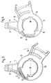
- the switch 1 is shown in FIG. 3, with a twist has not yet taken place.
- the rotatable housing 3 is namely a nose 11 connected, which upon rotation of the rotatable housing 3 with respect to the fixed housing 2 in a direction of rotation 14 in the counterclockwise direction is moved towards a resilient tongue 12 which is connected to the fixed housing 2.
- the nose 11 passes over the resilient tongue 12 to a snap point at which the resilient tongue 12 snaps back into its original position after the nose 11 has run over this resilient tongue 12, as can be seen from FIG. 4 is.
- the recess 8 has around the bayonet hook 10 rotated at least the width of the recess 8.
- the inner cylinder 7 on the rotatable housing 3 forms with the outer cylinder 9 on the fixed housing 2, a bearing around which the rotatable housing 3 is rotatable, starting from the snap point in the direction of rotation 14.
- the switching path formed in this way can still be divided by notches 15, 16, 17 in the fixed housing 2 are arranged, and in which a not shown locking element at Shifting from one gear to the next snaps into place.
- the approach 4 on the fixed housing 2 has a slot 5 in which a cable is operated to operate the bicycle transmission.
- the rotatable housing 3 has a slot radially inward in the mounting position of the locking point on a shaft 6, in which the nipple this Cable can be inserted and fastened from the direction of the slot 5.
- the switching range can be as wide as desired many notches 15, 16, 17 ... are designed so that bicycle gears with a variety of gears with the proposed inexpensive switch 1 be switched.
Abstract
Description
Die Erfindung betrifft einen Schalter für die Betätigung von Getrieben an Fahrrädern,
insbesondere einen Drehgriffschalter zur Montage an Lenkstangen gemäß
dem Oberbegriff des Anspruchs 1.The invention relates to a switch for the actuation of gears on bicycles,
in particular a rotary handle switch for mounting on handlebars according to
the preamble of
Mit der DE 44 20 125 A1 ist ein Drehgriffschalter bekannt geworden, bei welchem ein Griffgehäuse mit einem Drehring in der Weise verbunden ist, daß das Griffgehäuse aus zwei Halbschalen besteht und bei seiner Montage einen am Drehring befestigten Mitnehmer axial festlegt, wodurch beide, nämlich das Griffgehäuse und der Drehring in axialer Richtung miteinander verbunden sind. Nach dem Aufschieben des Griffgehäuses auf das Lenkerende läßt sich der Drehring infolge der axialen Fügeverbindung nicht mehr lösen.DE 44 20 125 A1 discloses a rotary handle switch in which a handle housing is connected to a rotating ring in such a way that Handle housing consists of two half-shells and one during assembly Rotating ring attached driver axially sets, causing both, namely the handle housing and the rotary ring are connected to one another in the axial direction. After the rotating ring can be pushed onto the handlebar end no longer loosen due to the axial joint connection.
Der in dieser Erfindung vorgeschlagene Drehgriffschalter verwendet zur Befestigung der Gehäuseteile, nämlich eines feststehenden Gehäuses mit einem verdrehbaren Gehäuse, ebenfalls eine Fügeverbindung: Das feststehende Gehäuse weist einen zylindrischen Fortsatz mit einem Außenzylinder auf, an dessen stirnseitigem Ende Bajonetthaken angeordnet sind, welche bei der Montage mit Ausnehmungen zusammenwirken, die an einem Innenzylinder des verdrehbaren Gehäuses angeordnet sind. Nach Zusammenschieben der beiden Gehäuseteile kann durch einfaches Verdrehen derselben gegeneinander eine axiale Sicherung durch Sperrung über die Bajonetthaken an der stirnseitigen Planfläche des verdrehbaren Gehäuses erreicht werden, so daß die Gehäuseteile dann nicht mehr voneinander in axialer Richtung gelöst werden können, wenn sie um einen bestimmten Winkelbetrag bis zu einem Einrastpunkt gegeneinander verdreht worden sind. Von Vorteil ist das Zusammenwirken des Innenzylinders des verdrehbaren Gehäuses mit dem Außenzylinder des feststehenden Gehäuses in sofern, als diese miteinander eine Lagerstelle bilden, welche unabhängig von ihrer Befestigung auf der Lenkstange wirkt. Der Einrastpunkt hat den Vorteil, daß von hier aus der eigentliche Schaltweg beginnen kann, wobei ausgeschlossen wird, daß sich die Schalter wieder lösen können, wenn beim Rückwärtsdrehen versucht wird, den Einrastpunkt zu überwinden. Abgesehen von der hier nicht dargestellten Befestigungseinrichtung an der Lenkstange sind alle Funktionen, die zum Betätigen der Fahrradgetriebe sowie zum Befestigen und Lagern der Gehäuse miteinander erforderlich sind, in den beiden Kunststoffgehäusen enthalten. Der Seilzug läßt sich im montierten Zustand des Schalters am Fahrrad bequem auswechseln und der Schalter weist in axialer Richtung im montierten Zustand eine sehr geringe Baulänge auf, wodurch der Schalter auch an geschwungenen Lenkstangen ohne besondere Hilfsmittel montierbar ist.The twist grip switch proposed in this invention is used for attachment the housing parts, namely a fixed housing with a rotatable Housing, also a joint: the fixed housing has a cylindrical extension with an outer cylinder, on the front side End bayonet hooks are arranged, which with assembly with recesses cooperate on an inner cylinder of the rotatable housing are arranged. After pushing the two housing parts together by simply twisting them against each other, secure them axially Locking via the bayonet hook on the front face of the rotatable Housing are reached so that the housing parts are then no longer apart can be solved in the axial direction if they are by a certain angular amount have been rotated against each other up to a locking point. From The advantage is the interaction of the inner cylinder of the rotatable housing with the outer cylinder of the fixed housing in so far as these together form a bearing which, regardless of its attachment to the Handlebar works. The locking point has the advantage that from here the actual Switching path can begin, whereby it is excluded that the switch if you try to turn it backwards, you can release the locking point to overcome. Except for the fastening device, not shown here on the handlebar are all functions for operating the bicycle transmission as well as for fastening and storing the housings together are contained in the two plastic housings. The cable can be in when the switch on the bike is installed, simply change it and the The switch has a very small overall length in the axial direction when assembled on, which makes the switch even on curved handlebars without any special Aid is mountable.
Die vorbeschriebenen Vorteile des Schalters sind das Ergebnis der Lösung der folgenden Aufgabe: Erstellung eines kostengünstigen Drehgriffschalters, der nicht mehr demontierbar zu sein braucht, sofern der mit ihm verbundene Seilzug austauschbar ist.The advantages of the switch described above are the result of the solution of the following task: creating an inexpensive twist grip switch that is not more need to be dismantled, provided that the cable connected to it is replaceable is.
Die Lösung der Aufgabe geht aus dem kennzeichnenden Teil des Anspruchs 1 sowie aus den Unteransprüchen hervor. Ein Ausführungsbeispiel eines kostengünstigen Drehgriffschalters wird in den anliegenden Zeichnungen erläutert. Es zeigen:
- Fig. 1
- ein auf einer Lenkstange eines Fahrrades montierbares feststehendes Gehäuse mit einem Außenzylinder, an dessen Stirnseite Bajonetthaken angeordnet sind;
- Fig. 2
- ein verdrehbares Gehäuse mit einem Innenzylinder und Ausnehmungen zur axialen Montage auf dem feststehenden Gehäuse gem. Fig. 1;
- Fig. 3
- das feststehende Gehäuse und das verdrehbare Gehäuse in Montagestellung, in welcher eine Nase des verdrehbaren Gehäuses in Montagedrehrichtung gesehen, vor einer federnden Zunge des feststehenden Gehäuses angeordnet ist;
- Fig. 4
- die Anordnung des Schalters gemäß Fig. 3, wobei die Nase durch Verdrehen des verdrehbaren Gehäuses die federnde Zunge überlaufen hat in der Stellung eines Einrastpunktes.
- Fig. 1
- a fixed on a handlebar of a bicycle fixed housing with an outer cylinder, on the front side of which bayonet hooks are arranged;
- Fig. 2
- a rotatable housing with an inner cylinder and recesses for axial mounting on the fixed housing acc. Fig. 1;
- Fig. 3
- the fixed housing and the rotatable housing in the assembly position, in which a nose of the rotatable housing seen in the direction of assembly rotation, is arranged in front of a resilient tongue of the fixed housing;
- Fig. 4
- the arrangement of the switch according to FIG. 3, wherein the nose has overflowed the resilient tongue by rotating the rotatable housing in the position of a locking point.
Ein Schalter 1, insbesondere ein Drehgriffschalter zur Betätigung von Fahrradgetrieben
besteht aus einem feststehenden Gehäuse 2 und einem verdrehbaren Gehäuse
3, wobei das feststehende Gehäuse 2 einen Außenzylinder 9 mit Bajonetthaken
10 an des Stirnseite des Außenzylinders 9 aufweist. Gemäß Fig. 1 ist das
feststehende Gehäuse mit einem Ansatz 4 perspektivisch in der Weise dargestellt,
daß der Außenzylinder 9 mit seinen Bajonetthaken 10 in Richtung auf das
verdrehbare Gehäuse 3 gemäß Fig. 2 weist, wobei das verdrehbare Gehäuse 3
mit einem Innenzylinder 7 und Ausnehmungen 8 in einer Stellung dargestellt ist,
die der Montagestellung entspricht, sofern das verdrehbare Gehäuse 3 gegen das
feststehende Gehäuse 2 entlang einer gemeinsamen Mittellinie verschoben wird.
Bei dieser Verschiebung durchwandern die Bajonetthaken 10 am feststehenden
Gehäuse 2 die Ausnehmungen 8 am verdrehbaren Gehäuse 3 und erscheinen auf
einer gegenüberliegenden Planfläche 13 des verdrehbaren Gehäuses 3 und erlauben
so eine Verdrehung der beiden Gehäuse 2 und 3 gegeneinander.A
In dieser Position ist der Schalter 1 gemäß Fig. 3 dargestellt, wobei eine Verdrehung
noch nicht stattgefunden hat. Mit dem verdrehbaren Gehäuse 3 ist nämlich
eine Nase 11 verbunden, welche bei einer Verdrehung des verdrehbaren Gehäuses
3 gegenüber dem feststehenden Gehäuse 2 in einer Drehrichtung 14 im Gegenuhrzeigersinn
in Richtung auf eine federnde Zunge 12 bewegt wird, welche
mit dem feststehenden Gehäuse 2 verbunden ist. Bei Verdrehung des verdrehbaren
Gehäuses 3 gegenüber dem feststehenden Gehäuse 2 in Drehrichtung 14
überfährt die Nase 11 die federnde Zunge 12 bis zu einem Einrastpunkt, bei welchem
die federnde Zunge 12 in ihre Ausgangsstellung zurückschnappt, nachdem
die Nase 11 diese federnde Zunge 12 überfahren hat, wie aus Fig. 4 ersichtlich
ist. In dieser Position hat sich die Ausnehmung 8 unter den Bajonetthaken 10 um
mindestens die Breite der Ausnehmung 8 hinweg verdreht.In this position, the
Der Innenzylinder 7 am verdrehbaren Gehäuse 3 bildet mit dem Außenzylinder 9
am feststehenden Gehäuse 2 eine Lagerstelle, um die das verdrehbare Gehäuse 3
verdrehbar ist, und zwar ausgehend vom Einrastpunkt in der Drehrichtung 14.
Beim Rückdrehen des verdrehbaren Gehäuses 3 kann der Einrastpunkt erreicht
aber nicht überfahren werden. Der auf diese Weise gebildete Schaltweg kann
noch durch Rasten 15,16,17 unterteilt werden, die im feststehenden Gehäuse
2angeordnet sind, und in welche ein hier nicht gezeigtes Rastelement beim
Schalten von einem Gang zum nächsten einrastet.The
Der Ansatz 4 am feststehenden Gehäuse 2 weist einen Schlitz 5 auf, in welchem
ein Seilzug zur Betätigung der Fahrradgetriebe geführt wird. In Verlängerung dieses
Schlitzes nach radial innen weist das verdrehbare Gehäuse 3 in der Montagestellung
des Einrastpunktes einen Schacht 6 auf, in welchen der Nippel dieses
Seilzuges aus der Richtung des Schlitzes 5 einlegbar und befestigbar ist. The
Der Schaltbereich, beginnend am Einrastpunkt, kann beliebig weit mit beliebig
vielen Rasten 15,16,17... ausgelegt werden, so daß auch Fahrradgetriebe mit
einer Vielzahl von Gängen mit dem vorgeschlagenen kostengünstigen Schalter 1
geschaltet werden.The switching range, starting at the snap-in point, can be as wide as desired
Claims (5)
dadurch gekennzeichnet, daß
characterized in that
dadurch gekennzeichnet,
daß der Einrastpunkt durch das Zusammenwirken einer Nase (11) mit einer federnden Zunge (12) hergestellt wird.Switch according to claim 1,
characterized,
that the locking point is produced by the interaction of a nose (11) with a resilient tongue (12).
dadurch gekennzeichnet,
daß die Nase (11) an einem der Gehäuse (2,3), vorzugsweise am verdrehbaren Gehäuse (3), und die federnde Zunge (12) am anderen der Gehäuse (2,3), vorzugsweise am feststehenden Gehäuse (2), angeordnet sind.Switch according to one of claims 1 or 2,
characterized,
that the nose (11) on one of the housings (2, 3), preferably on the rotatable housing (3), and the resilient tongue (12) on the other of the housings (2, 3), preferably on the fixed housing (2) are.
dadurch gekennzeichnet,
daß der Schaltbereich des verdrehbaren Gehäuses (3) gegenüber dem feststehenden Gehäuse (2) beim Einrastpunkt beginnt und sich durch Einschnappen eines Federelementes an einem der beiden Gehäuse (2,3), vorzugsweise am verdrehbaren Gehäuse (3), in Rasten (15,16,17) am anderen der beiden Gehäuse, vorzugsweise am feststehenden Gehäuse (2), erstreckt.Switch according to one of claims 1 to 3,
characterized,
that the switching range of the rotatable housing (3) with respect to the fixed housing (2) begins at the snap-in point and snaps (15,16 , 17) on the other of the two housings, preferably on the fixed housing (2).
dadurch gekennzeichnet,
daß die Aussparung (8) des verdrehbaren Gehäuses (3) in der Position des Einrastpunktes gegenüber den Bajonetthaken (10) des feststehenden Gehäuses (2) eine Winkelverdrehung zur axialen Arretierung der Gehäuse (2,3) gegeneinander aufweisen.Switch according to claim 1,
characterized,
that the recess (8) of the rotatable housing (3) in the position of the locking point with respect to the bayonet hook (10) of the fixed housing (2) has an angular rotation for axially locking the housing (2, 3) against one another.
Applications Claiming Priority (2)
| Application Number | Priority Date | Filing Date | Title |
|---|---|---|---|
| DE19723346 | 1997-06-04 | ||
| DE19723346A DE19723346A1 (en) | 1997-06-04 | 1997-06-04 | Twist shifter for bicycle transmissions |
Publications (3)
| Publication Number | Publication Date |
|---|---|
| EP0882645A2 true EP0882645A2 (en) | 1998-12-09 |
| EP0882645A3 EP0882645A3 (en) | 1999-06-23 |
| EP0882645B1 EP0882645B1 (en) | 2002-02-20 |
Family
ID=7831336
Family Applications (1)
| Application Number | Title | Priority Date | Filing Date |
|---|---|---|---|
| EP98108025A Expired - Lifetime EP0882645B1 (en) | 1997-06-04 | 1998-05-02 | Twist grip for a bicycle gear shift |
Country Status (4)
| Country | Link |
|---|---|
| US (1) | US5893573A (en) |
| EP (1) | EP0882645B1 (en) |
| AT (1) | ATE213475T1 (en) |
| DE (2) | DE19723346A1 (en) |
Cited By (1)
| Publication number | Priority date | Publication date | Assignee | Title |
|---|---|---|---|---|
| CN110958972A (en) * | 2019-09-09 | 2020-04-03 | 柠创控股有限公司 | Rotating handle type controller and electric two-wheeled vehicle provided with same |
Families Citing this family (10)
| Publication number | Priority date | Publication date | Assignee | Title |
|---|---|---|---|---|
| DE19915333A1 (en) | 1999-04-03 | 2000-10-05 | Sram De Gmbh | Grip shift for bicycles has cylindrical housing part with inner contour and outer diameter fabricated by injection-molding using one half of injection mold only |
| AU6066799A (en) * | 1999-11-26 | 2001-05-31 | Lily Hsu | Container device for separately enclosing two different substances |
| US6595894B2 (en) | 2001-03-09 | 2003-07-22 | Shimano (Singapore) Private Limited | Shift control device |
| US20030230160A1 (en) * | 2002-03-20 | 2003-12-18 | Ritchey Designs, Inc. | Barend mounted twist shifter with integrated brake actuator for bicycle |
| US7104154B2 (en) * | 2003-05-29 | 2006-09-12 | Shimano Inc. | Bicycle shift control device |
| US7013751B2 (en) * | 2003-05-29 | 2006-03-21 | Shimano Inc. | Bicycle shift control device |
| JP2007076545A (en) * | 2005-09-15 | 2007-03-29 | Shimano Inc | Bicycle speed change device |
| CN101626669B (en) * | 2008-07-11 | 2011-11-30 | 鸿富锦精密工业(深圳)有限公司 | Electronic equipment |
| US8944415B2 (en) | 2011-04-05 | 2015-02-03 | Dorel Juvenile Group, Inc. | Security enclosure |
| US10239581B2 (en) | 2011-08-26 | 2019-03-26 | Gevenalle, Inc | Bicycle brake and shift lever assembly |
Citations (1)
| Publication number | Priority date | Publication date | Assignee | Title |
|---|---|---|---|---|
| DE4420125A1 (en) | 1993-07-29 | 1995-02-02 | Fichtel & Sachs Ag | Twist-grip switch for bicycles |
Family Cites Families (10)
| Publication number | Priority date | Publication date | Assignee | Title |
|---|---|---|---|---|
| DE3727505C2 (en) * | 1986-09-09 | 1996-10-10 | Campagnolo Spa | Gear selector for a bicycle gear shift |
| JPS63129692U (en) * | 1987-02-18 | 1988-08-24 | ||
| FR2634722B1 (en) * | 1988-07-29 | 1990-11-09 | Huret Sachs Sa | CONTROL DEVICE FOR CYCLE DERAILLEUR |
| FR2656391B1 (en) * | 1989-12-27 | 1992-04-03 | Aerospatiale | SYSTEM FOR THE COAXIAL ASSEMBLY OF TWO PARTS OF REVOLUTION. |
| JPH0648366A (en) * | 1992-07-28 | 1994-02-22 | Maeda Kogyo Kk | Speed shift operation device for bicycle |
| US5310276A (en) * | 1992-12-21 | 1994-05-10 | Hutchinson | Connection device between two mechanical components |
| DE4402344C1 (en) * | 1994-01-27 | 1995-03-16 | Fichtel & Sachs Ag | Control device for ratchet-type locks for bicycle multi-speed drive hubs |
| US5588925A (en) * | 1994-12-02 | 1996-12-31 | Fichtel & Sachs Ag | Shifter for transmissions on bicycles |
| US5799541A (en) * | 1994-12-02 | 1998-09-01 | Fichtel & Sachs Ag | Twist-grip shifter for bicycles and a bicycle having a twist-grip shifter |
| EP0759393B1 (en) * | 1995-03-13 | 2002-08-21 | Sakae Co., Ltd. | Bicycle and speed change operating device for the same |
-
1997
- 1997-06-04 DE DE19723346A patent/DE19723346A1/en not_active Withdrawn
-
1998
- 1998-05-02 AT AT98108025T patent/ATE213475T1/en not_active IP Right Cessation
- 1998-05-02 EP EP98108025A patent/EP0882645B1/en not_active Expired - Lifetime
- 1998-05-02 DE DE59803120T patent/DE59803120D1/en not_active Expired - Lifetime
- 1998-06-03 US US09/089,691 patent/US5893573A/en not_active Expired - Fee Related
Patent Citations (1)
| Publication number | Priority date | Publication date | Assignee | Title |
|---|---|---|---|---|
| DE4420125A1 (en) | 1993-07-29 | 1995-02-02 | Fichtel & Sachs Ag | Twist-grip switch for bicycles |
Cited By (1)
| Publication number | Priority date | Publication date | Assignee | Title |
|---|---|---|---|---|
| CN110958972A (en) * | 2019-09-09 | 2020-04-03 | 柠创控股有限公司 | Rotating handle type controller and electric two-wheeled vehicle provided with same |
Also Published As
| Publication number | Publication date |
|---|---|
| EP0882645A3 (en) | 1999-06-23 |
| ATE213475T1 (en) | 2002-03-15 |
| DE19723346A1 (en) | 1998-12-10 |
| EP0882645B1 (en) | 2002-02-20 |
| DE59803120D1 (en) | 2002-03-28 |
| US5893573A (en) | 1999-04-13 |
Similar Documents
| Publication | Publication Date | Title |
|---|---|---|
| DE19981585B4 (en) | Arrangement for fastening a tubular element to a structural element of a motor vehicle body | |
| DE69731523T2 (en) | Two-wheel hub assembly device | |
| EP1084056B1 (en) | Twist grip shift lever for bicycles | |
| EP1157919B1 (en) | Integrated twist grip for a bicycle gear shift | |
| EP0882645B1 (en) | Twist grip for a bicycle gear shift | |
| DE4401272C1 (en) | Multiple sprocket for bicycle derailleurs | |
| DE10163349A1 (en) | Ratchet screwdriver has handle which can be rotated in counterclockwise direction to enable synchronous rotation of shaft mounting seat and drive shaft in counterclockwise direction | |
| DE4430375C2 (en) | Chain guide | |
| DE4141007C2 (en) | Device for percolating a device for connecting a gear lever arrangement to a steering lock | |
| DE3811757A1 (en) | Device for connecting a wheel rim to an axle of a wheel | |
| EP0703520A1 (en) | Gear shift lever for a motor vehicle gearbox | |
| DE4301504C2 (en) | Electrical connector | |
| DE3612418C2 (en) | ||
| DE19742065C1 (en) | Gear change control for motor vehicle drive | |
| DE4420125C2 (en) | Twist shifter for bicycles | |
| DE102006045639A1 (en) | Coupling system for connecting hose with connection bush, has connecting element and hose has connection at one of its end, which is inserted into or on connection bush | |
| DE4038345C1 (en) | Vehicle seat with adjustable lumbar support - has reduction gearing on drive for positioning cushion support | |
| DE3800361A1 (en) | REAR WHEEL DERAILLEUR FOR A BICYCLE GEAR | |
| DE2655053C3 (en) | Arrangement for the plug-in and detachable connection of an insert part with a receiving part without play in the direction of rotation | |
| DE2314959A1 (en) | SHIFT RODS OF A STEERING WHEEL GEAR OF A MOTOR VEHICLE | |
| WO2019192655A1 (en) | Electrical plug connector part and electrical plug connection system with lock | |
| DE2739870B2 (en) | Switching device for a motor vehicle transfer case | |
| DE19540897C1 (en) | Device for switching motor vehicle gearboxes | |
| EP1398555A1 (en) | Wear ring to be placed on a pipe, hose, cable or the like and corrugated pipe assembly incorporating said wear ring | |
| DE10352162B3 (en) | protection order |
Legal Events
| Date | Code | Title | Description |
|---|---|---|---|
| PUAI | Public reference made under article 153(3) epc to a published international application that has entered the european phase |
Free format text: ORIGINAL CODE: 0009012 |
|
| AK | Designated contracting states |
Kind code of ref document: A2 Designated state(s): AT DE FR GB SE |
|
| AX | Request for extension of the european patent |
Free format text: AL;LT;LV;MK;RO;SI |
|
| PUAL | Search report despatched |
Free format text: ORIGINAL CODE: 0009013 |
|
| AK | Designated contracting states |
Kind code of ref document: A3 Designated state(s): AT BE CH CY DE DK ES FI FR GB GR IE IT LI LU MC NL PT SE |
|
| AX | Request for extension of the european patent |
Free format text: AL;LT;LV;MK;RO;SI |
|
| 17P | Request for examination filed |
Effective date: 19990722 |
|
| AKX | Designation fees paid |
Free format text: AT DE FR GB SE |
|
| GRAG | Despatch of communication of intention to grant |
Free format text: ORIGINAL CODE: EPIDOS AGRA |
|
| GRAG | Despatch of communication of intention to grant |
Free format text: ORIGINAL CODE: EPIDOS AGRA |
|
| GRAH | Despatch of communication of intention to grant a patent |
Free format text: ORIGINAL CODE: EPIDOS IGRA |
|
| 17Q | First examination report despatched |
Effective date: 20010705 |
|
| GRAH | Despatch of communication of intention to grant a patent |
Free format text: ORIGINAL CODE: EPIDOS IGRA |
|
| REG | Reference to a national code |
Ref country code: GB Ref legal event code: IF02 |
|
| GRAA | (expected) grant |
Free format text: ORIGINAL CODE: 0009210 |
|
| AK | Designated contracting states |
Kind code of ref document: B1 Designated state(s): AT DE FR GB SE |
|
| REF | Corresponds to: |
Ref document number: 213475 Country of ref document: AT Date of ref document: 20020315 Kind code of ref document: T |
|
| REF | Corresponds to: |
Ref document number: 59803120 Country of ref document: DE Date of ref document: 20020328 |
|
| PG25 | Lapsed in a contracting state [announced via postgrant information from national office to epo] |
Ref country code: AT Free format text: LAPSE BECAUSE OF NON-PAYMENT OF DUE FEES Effective date: 20020502 |
|
| PGFP | Annual fee paid to national office [announced via postgrant information from national office to epo] |
Ref country code: GB Payment date: 20020502 Year of fee payment: 5 |
|
| PGFP | Annual fee paid to national office [announced via postgrant information from national office to epo] |
Ref country code: FR Payment date: 20020513 Year of fee payment: 5 |
|
| PG25 | Lapsed in a contracting state [announced via postgrant information from national office to epo] |
Ref country code: SE Free format text: LAPSE BECAUSE OF FAILURE TO SUBMIT A TRANSLATION OF THE DESCRIPTION OR TO PAY THE FEE WITHIN THE PRESCRIBED TIME-LIMIT Effective date: 20020520 |
|
| GBT | Gb: translation of ep patent filed (gb section 77(6)(a)/1977) |
Effective date: 20020502 |
|
| ET | Fr: translation filed | ||
| PLBE | No opposition filed within time limit |
Free format text: ORIGINAL CODE: 0009261 |
|
| STAA | Information on the status of an ep patent application or granted ep patent |
Free format text: STATUS: NO OPPOSITION FILED WITHIN TIME LIMIT |
|
| 26N | No opposition filed |
Effective date: 20021121 |
|
| PG25 | Lapsed in a contracting state [announced via postgrant information from national office to epo] |
Ref country code: GB Free format text: LAPSE BECAUSE OF NON-PAYMENT OF DUE FEES Effective date: 20030502 |
|
| GBPC | Gb: european patent ceased through non-payment of renewal fee |
Effective date: 20030502 |
|
| PG25 | Lapsed in a contracting state [announced via postgrant information from national office to epo] |
Ref country code: FR Free format text: LAPSE BECAUSE OF NON-PAYMENT OF DUE FEES Effective date: 20040130 |
|
| REG | Reference to a national code |
Ref country code: FR Ref legal event code: ST |
|
| PGFP | Annual fee paid to national office [announced via postgrant information from national office to epo] |
Ref country code: DE Payment date: 20130528 Year of fee payment: 16 |
|
| REG | Reference to a national code |
Ref country code: DE Ref legal event code: R119 Ref document number: 59803120 Country of ref document: DE |
|
| REG | Reference to a national code |
Ref country code: DE Ref legal event code: R119 Ref document number: 59803120 Country of ref document: DE Effective date: 20141202 |
|
| PG25 | Lapsed in a contracting state [announced via postgrant information from national office to epo] |
Ref country code: DE Free format text: LAPSE BECAUSE OF NON-PAYMENT OF DUE FEES Effective date: 20141202 |