EP0882566A1 - Adjustable clamping frame for the moulding stations of a thermoforming machine - Google Patents
Adjustable clamping frame for the moulding stations of a thermoforming machine Download PDFInfo
- Publication number
- EP0882566A1 EP0882566A1 EP98110099A EP98110099A EP0882566A1 EP 0882566 A1 EP0882566 A1 EP 0882566A1 EP 98110099 A EP98110099 A EP 98110099A EP 98110099 A EP98110099 A EP 98110099A EP 0882566 A1 EP0882566 A1 EP 0882566A1
- Authority
- EP
- European Patent Office
- Prior art keywords
- longitudinal
- plates
- webs
- frame according
- tenter frame
- Prior art date
- Legal status (The legal status is an assumption and is not a legal conclusion. Google has not performed a legal analysis and makes no representation as to the accuracy of the status listed.)
- Granted
Links
Images


Classifications
-
- B—PERFORMING OPERATIONS; TRANSPORTING
- B29—WORKING OF PLASTICS; WORKING OF SUBSTANCES IN A PLASTIC STATE IN GENERAL
- B29C—SHAPING OR JOINING OF PLASTICS; SHAPING OF MATERIAL IN A PLASTIC STATE, NOT OTHERWISE PROVIDED FOR; AFTER-TREATMENT OF THE SHAPED PRODUCTS, e.g. REPAIRING
- B29C51/00—Shaping by thermoforming, i.e. shaping sheets or sheet like preforms after heating, e.g. shaping sheets in matched moulds or by deep-drawing; Apparatus therefor
- B29C51/26—Component parts, details or accessories; Auxiliary operations
- B29C51/261—Handling means, e.g. transfer means, feeding means
- B29C51/262—Clamping means for the sheets, e.g. clamping frames
Definitions
- the invention relates to an adjustable stenter for the molding station of a thermoforming machine with which heated Thermoplastic sheets by differential pressure be deformed by means of a shape, according to the genus of the main claim.
- Such molding stations have in the Always open a blow box on the top a fixed stenter sits in cooperation with the plate is clamped in a vertically movable upper frame.
- the fixed clamping frame is infinitely adjustable design (DE 44 24 845 C 2) in which it consists of four plates exists that can be shifted towards each other. Depending on Shifting these plates creates a larger or smaller window.
- This version of the stenter cannot be used on thermoforming machines, their forming station for automatic loading with Plates and / or for the removal of molded parts via a Transport device is provided.
- This transport facility has a certain height and transports the plastic plate at a certain distance from the surface of the Blow box cover. The plate edge must be on two longitudinal edges can be taken.
- the invention was based, an infinitely the task adjustable stenter so that it can be used for a automatic feeding of plates and / or for an automatic Transport of the molded parts can be used. He should be very stable and simple Allow mounting of bracket for the plate. It should either be rigid crossbars or telescopically movable Crossbars can be used.
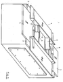
- the stenter 1 covers the blow box 2 in the molding station a thermoforming machine. It consists of two fixed on Board 4 of the blow box 2 at a distance A attached plates 3, which extend over the entire length of the blow box 2. Two plates 5 run between the plates 3 relative to each other and to the plates 3 slidably formed are. They are at the same height as the plates 3 and are led to them.
- Two transverse webs 6 are seated between the two longitudinal webs 10. In the simplest version, these are rigid as one part trained and are attached to the longitudinal webs 10. Per The size of the plate 7 in the transverse direction becomes a set of transverse webs 6 needed. It is more universal to use the crossbars 6 as in the Figures 1 and 3 shown, telescopic in Form of two crossbars 8, 9. A third solution is in Figure 4 shown. At each plate 5 sits in the middle rigid web 20, on each leg 11 there is a web 21 Bars 20, 21 also work together telescopically and can bridge a certain latitude. The The upper edge of the crossbars 6 and the upper edge of the legs 11 the longitudinal webs 10 are at the same height and carry the Plastic plate 7, which cooperates with a height adjustable Frame 24 is clamped.
- the plastic plate 7 is from the side on Transport system 16 introduced, consisting of two guide rails 17 and each with a circulating transport chain 18 Pointed tabs and support strips 19. This transport system also takes over the removal of the molded parts 25 their manufacture.
Abstract
Description
Die Erfindung betrifft einen verstellbaren Spannrahmen für die Formstation einer Thermoformmaschine, mit der erwärmte Platten aus thermoplastischem Kunststoff durch Differenzdruck mittels einer Form verformt werden, nach der Gattung des Hauptanspruches. Solche Formstationen weisen in der Regel einen geschlossenen Blaskasten auf, an dessen Oberseite ein fester Spannrahmen sitzt, der im Zusammenwirken mit einem höhenbeweglichen Oberrahmen die Platte einspannt. Um die Formstation für verschiedene Größen von Formteilen und damit Plattenzuschnitten verwenden zu können, ist es bekannt, den festen Spannrahmen stufenlos verstellbar zu gestalten (DE 44 24 845 C 2), in dem er aus vier Platten besteht, die zueinander verschoben werden können. Je nach Verschiebung dieser Platten entsteht ein größeres oder kleineres Fenster.The invention relates to an adjustable stenter for the molding station of a thermoforming machine with which heated Thermoplastic sheets by differential pressure be deformed by means of a shape, according to the genus of the main claim. Such molding stations have in the Always open a blow box on the top a fixed stenter sits in cooperation with the plate is clamped in a vertically movable upper frame. Around the molding station for different sizes of molded parts and in order to be able to use plate blanks, it is known the fixed clamping frame is infinitely adjustable design (DE 44 24 845 C 2) in which it consists of four plates exists that can be shifted towards each other. Depending on Shifting these plates creates a larger or smaller window.
Nachteilig bei dieser Ausführung des Spannrahmens ist es, daß er nicht bei Thermoformmaschinen eingesetzt werden kann, deren Formstation für eine automatische Beschickung mit Platten und/oder für das Entnehmen von Formteilen über eine Transporteinrichtung vorgesehen ist. Diese Transporteinrichtung hat eine gewisse Bauhöhe und transportiert die Kunststoffplatte in einem gewissen Abstand von der Oberfläche der Blaskastenabdeckung. Der Plattenrand muß an zwei Längskanten ergriffen werden können.The disadvantage of this version of the stenter is that that it cannot be used on thermoforming machines, their forming station for automatic loading with Plates and / or for the removal of molded parts via a Transport device is provided. This transport facility has a certain height and transports the plastic plate at a certain distance from the surface of the Blow box cover. The plate edge must be on two longitudinal edges can be taken.
Der Erfindung lag die Aufgabe zugrunde, einen stufenlos verstellbaren Spannrahmen so auszubilden, daß er für eine automatische Zufuhr von Platten und/oder für einen automatischen Austransport der Formteile verwendet werden kann. Er sollte dabei eine hohe Stabilität aufweisen und eine einfache Montage von Hochhaltern für die Platte ermöglichen. Es sollten wahlweise starre Querstege oder teleskopartig verschiebbare Querstege eingesetzt werden können.The invention was based, an infinitely the task adjustable stenter so that it can be used for a automatic feeding of plates and / or for an automatic Transport of the molded parts can be used. He should be very stable and simple Allow mounting of bracket for the plate. It should either be rigid crossbars or telescopically movable Crossbars can be used.
Zur Lösung der Aufgabe werden die kennzeichnenden Merkmale des Hauptanspruches vorgeschlagen. Hinsichtlich vorteilhafter Weiterbildungen wird auf die Unteransprüche verwiesen.To solve the problem, the characteristic features of the main claim proposed. In terms of more advantageous Further training is referred to the subclaims.
Der Gegenstand der Erfindung wird nachfolgend anhand der schematischen Zeichnungen näher beschrieben. Es zeigt:
- Figur 1 -
- eine perspektifische Ansicht von Blaskasten und festem Spannrahmen
- Figur 2 -
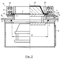
- einen Querschnitt durch den Spannrahmen einschließlich Blaskasten und Formtisch der Formstation
- Figur 3 -
- einen Längsschnitt (Ausschnitt) durch Spannrahmen und Blaskasten
- Figur 4 -
- eine Teildraufsicht auf den Spannrahmen gemäß einer Variation.
- Figure 1 -
- a perspective view of the blow box and fixed stenter
- Figure 2 -
- a cross section through the clamping frame including blow box and molding table of the molding station
- Figure 3 -
- a longitudinal section (detail) through the tenter and blow box
- Figure 4 -
- a partial plan view of the tenter frame according to a variation.
Der Spannrahmen 1 deckt den Blaskasten 2 in der Formstation
einer Thermoformmaschine ab. Er besteht aus zwei fest am
Bord 4 des Blaskastens 2 im Abstand A angebrachten Platten
3, die sich über die ganze Länge des Blaskastens 2 erstrekken.
Zwischen den Platten 3 verlaufen zwei Platten 5, die
relativ zueinander und zu den Platten 3 verschiebbar ausgebildet
sind. Sie liegen auf gleicher Höhe wie die Platten 3
und sind zu diesen geführt.The
Auf den beiden starren Platten 3 sitzt je ein winkelförmiger
Längssteg 10, der sich mit dem einen Schenkel 12 auf der
Platte 3 abstützt, der zweite Schenkel 11 ragt nach oben und
bildet mit der Oberkante die Auflage für die Kunststoffplatte
7. Beide Längsstege 10 können zueinander über zwei Gewindespindeln
13 mit Rechts/Linksgewinde von Hand oder über
einen Motor 22 verstellt werden. Sie sind vorzugsweise mit
einer Gleichlaufeinrichtung versehen, bestehend aus zwei
Kettenrädern 14 und einer Rollenkette 15.An angular one sits on each of the two
Zwischen den beiden Längsstegen 10 sitzen zwei Querstege 6.
In einfachster Ausführung sind diese starr als ein Teil
ausgebildet und werden an den Längsstegen 10 befestigt. Pro
Größe der Platte 7 in Querrichtung wird ein Satz Querstege 6
benötigt. Universeller ist es, die Querstege 6 wie in den
Figuren 1 und 3 dargestellt, teleskopartig auszubilden in
Form von zwei Querstegen 8, 9. Eine dritte Lösung ist in
Figur 4 dargestellt. An jeder Platte 5 sitzt mittig ein
starrer Steg 20, an jedem Schenkel 11 sitzt ein Steg 21. Die
Stege 20, 21 arbeiten ebenfalls teleskopartig zusammen und
können einen bestimmten Breitenbereich überbrücken. Die
Oberkante der Querstege 6 und die Oberkante der Schenkel 11
der Längsstege 10 liegen auf gleicher Höhe und tragen die
Kunststoffplatte 7, die im Zusammenwirken mit einem höhenverstellbaren
Rahmen 24 eingespannt wird.Two
Die Kunststoffplatte 7 wird von der Seite her über ein
Transportsystem 16 herangeführt, bestehend aus zwei Führungsleisten
17 und je einer umlaufenden Transportkette 18 mit
Spitzlaschen sowie Auflagenleisten 19. Dieses Transportsystem
übernimmt auch den Austransport der Formteile 25 nach
ihrer Herstellung.The
Falls erforderlich, können in einfacher Weise zwischen den
Längsholmen 10 oder zwischen den starren Stegen 20 Hochhalter
in Form von Stegen oder Drähten 23 quer bzw. längs
angebracht werden, um die erwärmte und zum Durchhängen
neigende Kunststoffplatte 7 abzustützen.If necessary, you can easily switch between the
Claims (7)
Applications Claiming Priority (2)
| Application Number | Priority Date | Filing Date | Title |
|---|---|---|---|
| DE19723561A DE19723561C2 (en) | 1997-06-05 | 1997-06-05 | Adjustable clamping frame for the molding station of a thermoforming machine |
| DE19723561 | 1997-06-05 |
Publications (2)
| Publication Number | Publication Date |
|---|---|
| EP0882566A1 true EP0882566A1 (en) | 1998-12-09 |
| EP0882566B1 EP0882566B1 (en) | 2001-09-19 |
Family
ID=7831469
Family Applications (1)
| Application Number | Title | Priority Date | Filing Date |
|---|---|---|---|
| EP98110099A Expired - Lifetime EP0882566B1 (en) | 1997-06-05 | 1998-06-03 | Adjustable clamping frame for the moulding stations of a thermoforming machine |
Country Status (2)
| Country | Link |
|---|---|
| EP (1) | EP0882566B1 (en) |
| DE (2) | DE19723561C2 (en) |
Cited By (5)
| Publication number | Priority date | Publication date | Assignee | Title |
|---|---|---|---|---|
| EP0953427A1 (en) * | 1998-04-01 | 1999-11-03 | Adolf Illig Maschinenbau GmbH & Co | Adjustable clamping frame for a moulding station of a thermoforming machine |
| EP1153729A2 (en) * | 2000-05-08 | 2001-11-14 | Rigo Group S.R.L. | Extensible gripper for clamping the head portions of plastics material plates and thermoforming apparatus used |
| EP1876011A2 (en) * | 2006-07-07 | 2008-01-09 | Forma S.R.L. | Telescopically adjustable covering device, for the vacuum box of thermoforming machines |
| EP2103414A1 (en) | 2008-03-17 | 2009-09-23 | Bruno Moretti | An adjustable clamping table for thermoforming machines |
| EP2465664A1 (en) | 2010-12-20 | 2012-06-20 | Forma S.r.l. | Mobile-plate assembly for a thermoforming station |
Families Citing this family (3)
| Publication number | Priority date | Publication date | Assignee | Title |
|---|---|---|---|---|
| DE102004045243B4 (en) * | 2004-09-17 | 2006-06-14 | Illig Maschinenbau Gmbh & Co. Kg | Heating arrangement for plastic film or sheet thermoforming tool has lower heating plate with larger dimensions than upper heating plate and supports spacers extending to tool base |
| DE102013004623B4 (en) | 2013-03-15 | 2020-12-31 | Illig Maschinenbau Gmbh & Co. Kg | Device for clamping a blank of a tabular thermoplastic semi-finished product |
| EP3470204A1 (en) | 2017-10-13 | 2019-04-17 | Cannon Ergos S.p.A. | Adjustable dimensional frame for a thermoforming machine and adjustment method |
Citations (5)
| Publication number | Priority date | Publication date | Assignee | Title |
|---|---|---|---|---|
| AT223371B (en) * | 1960-03-21 | 1962-09-10 | Adolf Ing Hoeger | Stretching frames for films or plates, in particular made of plastic |
| US5167969A (en) * | 1991-04-09 | 1992-12-01 | Demaio Jr Joseph T | Split frame for rotary vacuum mold unit |
| EP0623449A1 (en) * | 1993-05-04 | 1994-11-09 | Maschinenfabrik Georg Geiss | Clamping frame for deep-drawing machine |
| EP0692365A1 (en) * | 1994-07-14 | 1996-01-17 | Maschinenfabrik Georg Geiss | Cover plate for vacuum forming machine |
| DE19536867C1 (en) * | 1995-10-03 | 1996-11-14 | Illig Maschinenbau Adolf | Non-welded adaptable size redn. frame for plastic thermo-form appts. |
Family Cites Families (1)
| Publication number | Priority date | Publication date | Assignee | Title |
|---|---|---|---|---|
| DE2427311A1 (en) * | 1974-06-06 | 1975-12-18 | Frank & Co L E | Variable size mould for thermoforming plastics trays - is made of straight bars abutting at T connections |
-
1997
- 1997-06-05 DE DE19723561A patent/DE19723561C2/en not_active Expired - Fee Related
-
1998
- 1998-06-03 EP EP98110099A patent/EP0882566B1/en not_active Expired - Lifetime
- 1998-06-03 DE DE59801497T patent/DE59801497D1/en not_active Expired - Lifetime
Patent Citations (5)
| Publication number | Priority date | Publication date | Assignee | Title |
|---|---|---|---|---|
| AT223371B (en) * | 1960-03-21 | 1962-09-10 | Adolf Ing Hoeger | Stretching frames for films or plates, in particular made of plastic |
| US5167969A (en) * | 1991-04-09 | 1992-12-01 | Demaio Jr Joseph T | Split frame for rotary vacuum mold unit |
| EP0623449A1 (en) * | 1993-05-04 | 1994-11-09 | Maschinenfabrik Georg Geiss | Clamping frame for deep-drawing machine |
| EP0692365A1 (en) * | 1994-07-14 | 1996-01-17 | Maschinenfabrik Georg Geiss | Cover plate for vacuum forming machine |
| DE19536867C1 (en) * | 1995-10-03 | 1996-11-14 | Illig Maschinenbau Adolf | Non-welded adaptable size redn. frame for plastic thermo-form appts. |
Cited By (8)
| Publication number | Priority date | Publication date | Assignee | Title |
|---|---|---|---|---|
| EP0953427A1 (en) * | 1998-04-01 | 1999-11-03 | Adolf Illig Maschinenbau GmbH & Co | Adjustable clamping frame for a moulding station of a thermoforming machine |
| EP1153729A2 (en) * | 2000-05-08 | 2001-11-14 | Rigo Group S.R.L. | Extensible gripper for clamping the head portions of plastics material plates and thermoforming apparatus used |
| EP1153729A3 (en) * | 2000-05-08 | 2003-10-08 | Rigo Group S.R.L. | Extensible gripper for clamping the head portions of plastics material plates and thermoforming apparatus used |
| EP1876011A2 (en) * | 2006-07-07 | 2008-01-09 | Forma S.R.L. | Telescopically adjustable covering device, for the vacuum box of thermoforming machines |
| EP1876011A3 (en) * | 2006-07-07 | 2008-10-29 | Forma S.R.L. | Telescopically adjustable covering device, for the vacuum box of thermoforming machines |
| EP2103414A1 (en) | 2008-03-17 | 2009-09-23 | Bruno Moretti | An adjustable clamping table for thermoforming machines |
| EP2465664A1 (en) | 2010-12-20 | 2012-06-20 | Forma S.r.l. | Mobile-plate assembly for a thermoforming station |
| ITMI20102323A1 (en) * | 2010-12-20 | 2012-06-21 | Forma Srl | MOBILE PLATE SYSTEM FOR A THERMOFORMING STATION. |
Also Published As
| Publication number | Publication date |
|---|---|
| EP0882566B1 (en) | 2001-09-19 |
| DE59801497D1 (en) | 2001-10-25 |
| DE19723561A1 (en) | 1998-12-10 |
| DE19723561C2 (en) | 2002-06-27 |
Similar Documents
| Publication | Publication Date | Title |
|---|---|---|
| DE3222951A1 (en) | BACKREST FOR A VEHICLE SEAT, ESPECIALLY A MOTOR VEHICLE SEAT | |
| EP0882566A1 (en) | Adjustable clamping frame for the moulding stations of a thermoforming machine | |
| EP1080869B1 (en) | Heating station for heating plates made of a thermoplastic material | |
| DE4205746C2 (en) | Device for gluing flat workpieces | |
| DE4424845C2 (en) | Cover plate for vacuum molding machines | |
| EP0953427B1 (en) | Adjustable clamping frame for a moulding station of a thermoforming machine | |
| DE3225533C2 (en) | ||
| EP0879692B1 (en) | Forming station for deep drawing a heated thermoplastic sheet | |
| DE3103038A1 (en) | Process for producing a hollow object from thermoplastic material, for example a surfboard, and apparatus for carrying out the process | |
| DE4001740C2 (en) | Device for laying out a web | |
| EP0437858B1 (en) | Apparatus for making blanks with pattern on the upper surface for bricks, tiles or the same | |
| DE3126216C2 (en) | ||
| DE3328745C2 (en) | Roller conveyor | |
| EP1302303B1 (en) | Apparatus for deforming two plates or film web sections in a forming station | |
| DE1454994A1 (en) | Process and device for preparing thermoplastic plastic films for differential pressure deformation | |
| DE2603782C2 (en) | Device for producing a curved molded part from a film section made of thermoplastic material | |
| DE7301715U (en) | Plate forming machine | |
| EP0684122A2 (en) | Apparatus for manufacturing deep drawn cups with a foot | |
| EP0884161B1 (en) | Moulding or punching station | |
| DE7501702U (en) | THERMOFORMING MACHINE | |
| EP0823391A2 (en) | Device for the treatment of ply-material, particularly for the folding of paper | |
| DE2545481A1 (en) | MACHINE FOR ERECTING SHELLS FROM CUT TO SHEETS | |
| DE1504301A1 (en) | Method and device for shrinking plastic strips | |
| DE1902442A1 (en) | Facility for the production of asbestos cement panels | |
| DE2115603A1 (en) | Device for forming a transportable unit or packaging |
Legal Events
| Date | Code | Title | Description |
|---|---|---|---|
| PUAI | Public reference made under article 153(3) epc to a published international application that has entered the european phase |
Free format text: ORIGINAL CODE: 0009012 |
|
| 17P | Request for examination filed |
Effective date: 19980907 |
|
| AK | Designated contracting states |
Kind code of ref document: A1 Designated state(s): DE ES FR GB IT NL |
|
| AX | Request for extension of the european patent |
Free format text: AL;LT;LV;MK;RO;SI |
|
| AKX | Designation fees paid |
Free format text: DE ES FR GB IT NL |
|
| 17Q | First examination report despatched |
Effective date: 20000609 |
|
| GRAG | Despatch of communication of intention to grant |
Free format text: ORIGINAL CODE: EPIDOS AGRA |
|
| GRAG | Despatch of communication of intention to grant |
Free format text: ORIGINAL CODE: EPIDOS AGRA |
|
| GRAH | Despatch of communication of intention to grant a patent |
Free format text: ORIGINAL CODE: EPIDOS IGRA |
|
| GRAH | Despatch of communication of intention to grant a patent |
Free format text: ORIGINAL CODE: EPIDOS IGRA |
|
| GRAA | (expected) grant |
Free format text: ORIGINAL CODE: 0009210 |
|
| AK | Designated contracting states |
Kind code of ref document: B1 Designated state(s): DE ES FR GB IT NL |
|
| PG25 | Lapsed in a contracting state [announced via postgrant information from national office to epo] |
Ref country code: NL Free format text: LAPSE BECAUSE OF FAILURE TO SUBMIT A TRANSLATION OF THE DESCRIPTION OR TO PAY THE FEE WITHIN THE PRESCRIBED TIME-LIMIT Effective date: 20010919 |
|
| REF | Corresponds to: |
Ref document number: 59801497 Country of ref document: DE Date of ref document: 20011025 |
|
| REG | Reference to a national code |
Ref country code: GB Ref legal event code: IF02 |
|
| ET | Fr: translation filed | ||
| GBT | Gb: translation of ep patent filed (gb section 77(6)(a)/1977) |
Effective date: 20011214 |
|
| NLV1 | Nl: lapsed or annulled due to failure to fulfill the requirements of art. 29p and 29m of the patents act | ||
| PG25 | Lapsed in a contracting state [announced via postgrant information from national office to epo] |
Ref country code: ES Free format text: LAPSE BECAUSE OF FAILURE TO SUBMIT A TRANSLATION OF THE DESCRIPTION OR TO PAY THE FEE WITHIN THE PRESCRIBED TIME-LIMIT Effective date: 20020326 |
|
| RAP2 | Party data changed (patent owner data changed or rights of a patent transferred) |
Owner name: ADOLF ILLIG MASCHINENBAU GMBH & CO. KG |
|
| PLBE | No opposition filed within time limit |
Free format text: ORIGINAL CODE: 0009261 |
|
| STAA | Information on the status of an ep patent application or granted ep patent |
Free format text: STATUS: NO OPPOSITION FILED WITHIN TIME LIMIT |
|
| 26N | No opposition filed | ||
| REG | Reference to a national code |
Ref country code: FR Ref legal event code: CD Ref country code: FR Ref legal event code: CA |
|
| REG | Reference to a national code |
Ref country code: FR Ref legal event code: CD |
|
| REG | Reference to a national code |
Ref country code: FR Ref legal event code: PLFP Year of fee payment: 19 |
|
| REG | Reference to a national code |
Ref country code: FR Ref legal event code: PLFP Year of fee payment: 20 |
|
| PGFP | Annual fee paid to national office [announced via postgrant information from national office to epo] |
Ref country code: FR Payment date: 20170621 Year of fee payment: 20 Ref country code: GB Payment date: 20170626 Year of fee payment: 20 |
|
| PGFP | Annual fee paid to national office [announced via postgrant information from national office to epo] |
Ref country code: IT Payment date: 20170622 Year of fee payment: 20 |
|
| PGFP | Annual fee paid to national office [announced via postgrant information from national office to epo] |
Ref country code: DE Payment date: 20170707 Year of fee payment: 20 |
|
| REG | Reference to a national code |
Ref country code: DE Ref legal event code: R071 Ref document number: 59801497 Country of ref document: DE |
|
| REG | Reference to a national code |
Ref country code: GB Ref legal event code: PE20 Expiry date: 20180602 |
|
| PG25 | Lapsed in a contracting state [announced via postgrant information from national office to epo] |
Ref country code: GB Free format text: LAPSE BECAUSE OF EXPIRATION OF PROTECTION Effective date: 20180602 |