EP0881738A2 - Generator powered electrically heated catalyst system - Google Patents
Generator powered electrically heated catalyst system Download PDFInfo
- Publication number
- EP0881738A2 EP0881738A2 EP98303804A EP98303804A EP0881738A2 EP 0881738 A2 EP0881738 A2 EP 0881738A2 EP 98303804 A EP98303804 A EP 98303804A EP 98303804 A EP98303804 A EP 98303804A EP 0881738 A2 EP0881738 A2 EP 0881738A2
- Authority
- EP
- European Patent Office
- Prior art keywords
- generator
- electrical
- rectifier bridge
- charging system
- catalyst
- Prior art date
- Legal status (The legal status is an assumption and is not a legal conclusion. Google has not performed a legal analysis and makes no representation as to the accuracy of the status listed.)
- Withdrawn
Links
Images
Classifications
-
- F—MECHANICAL ENGINEERING; LIGHTING; HEATING; WEAPONS; BLASTING
- F01—MACHINES OR ENGINES IN GENERAL; ENGINE PLANTS IN GENERAL; STEAM ENGINES
- F01N—GAS-FLOW SILENCERS OR EXHAUST APPARATUS FOR MACHINES OR ENGINES IN GENERAL; GAS-FLOW SILENCERS OR EXHAUST APPARATUS FOR INTERNAL COMBUSTION ENGINES
- F01N11/00—Monitoring or diagnostic devices for exhaust-gas treatment apparatus, e.g. for catalytic activity
-
- F—MECHANICAL ENGINEERING; LIGHTING; HEATING; WEAPONS; BLASTING
- F01—MACHINES OR ENGINES IN GENERAL; ENGINE PLANTS IN GENERAL; STEAM ENGINES
- F01N—GAS-FLOW SILENCERS OR EXHAUST APPARATUS FOR MACHINES OR ENGINES IN GENERAL; GAS-FLOW SILENCERS OR EXHAUST APPARATUS FOR INTERNAL COMBUSTION ENGINES
- F01N3/00—Exhaust or silencing apparatus having means for purifying, rendering innocuous, or otherwise treating exhaust
- F01N3/08—Exhaust or silencing apparatus having means for purifying, rendering innocuous, or otherwise treating exhaust for rendering innocuous
- F01N3/10—Exhaust or silencing apparatus having means for purifying, rendering innocuous, or otherwise treating exhaust for rendering innocuous by thermal or catalytic conversion of noxious components of exhaust
- F01N3/18—Exhaust or silencing apparatus having means for purifying, rendering innocuous, or otherwise treating exhaust for rendering innocuous by thermal or catalytic conversion of noxious components of exhaust characterised by methods of operation; Control
- F01N3/20—Exhaust or silencing apparatus having means for purifying, rendering innocuous, or otherwise treating exhaust for rendering innocuous by thermal or catalytic conversion of noxious components of exhaust characterised by methods of operation; Control specially adapted for catalytic conversion ; Methods of operation or control of catalytic converters
- F01N3/2006—Periodically heating or cooling catalytic reactors, e.g. at cold starting or overheating
- F01N3/2013—Periodically heating or cooling catalytic reactors, e.g. at cold starting or overheating using electric or magnetic heating means
-
- H—ELECTRICITY
- H02—GENERATION; CONVERSION OR DISTRIBUTION OF ELECTRIC POWER
- H02J—CIRCUIT ARRANGEMENTS OR SYSTEMS FOR SUPPLYING OR DISTRIBUTING ELECTRIC POWER; SYSTEMS FOR STORING ELECTRIC ENERGY
- H02J7/00—Circuit arrangements for charging or depolarising batteries or for supplying loads from batteries
- H02J7/14—Circuit arrangements for charging or depolarising batteries or for supplying loads from batteries for charging batteries from dynamo-electric generators driven at varying speed, e.g. on vehicle
- H02J7/1438—Circuit arrangements for charging or depolarising batteries or for supplying loads from batteries for charging batteries from dynamo-electric generators driven at varying speed, e.g. on vehicle in combination with power supplies for loads other than batteries
-
- F—MECHANICAL ENGINEERING; LIGHTING; HEATING; WEAPONS; BLASTING
- F01—MACHINES OR ENGINES IN GENERAL; ENGINE PLANTS IN GENERAL; STEAM ENGINES
- F01N—GAS-FLOW SILENCERS OR EXHAUST APPARATUS FOR MACHINES OR ENGINES IN GENERAL; GAS-FLOW SILENCERS OR EXHAUST APPARATUS FOR INTERNAL COMBUSTION ENGINES
- F01N2550/00—Monitoring or diagnosing the deterioration of exhaust systems
- F01N2550/22—Monitoring or diagnosing the deterioration of exhaust systems of electric heaters for exhaust systems or their power supply
-
- Y—GENERAL TAGGING OF NEW TECHNOLOGICAL DEVELOPMENTS; GENERAL TAGGING OF CROSS-SECTIONAL TECHNOLOGIES SPANNING OVER SEVERAL SECTIONS OF THE IPC; TECHNICAL SUBJECTS COVERED BY FORMER USPC CROSS-REFERENCE ART COLLECTIONS [XRACs] AND DIGESTS
- Y02—TECHNOLOGIES OR APPLICATIONS FOR MITIGATION OR ADAPTATION AGAINST CLIMATE CHANGE
- Y02T—CLIMATE CHANGE MITIGATION TECHNOLOGIES RELATED TO TRANSPORTATION
- Y02T10/00—Road transport of goods or passengers
- Y02T10/10—Internal combustion engine [ICE] based vehicles
- Y02T10/12—Improving ICE efficiencies
-
- Y—GENERAL TAGGING OF NEW TECHNOLOGICAL DEVELOPMENTS; GENERAL TAGGING OF CROSS-SECTIONAL TECHNOLOGIES SPANNING OVER SEVERAL SECTIONS OF THE IPC; TECHNICAL SUBJECTS COVERED BY FORMER USPC CROSS-REFERENCE ART COLLECTIONS [XRACs] AND DIGESTS
- Y02—TECHNOLOGIES OR APPLICATIONS FOR MITIGATION OR ADAPTATION AGAINST CLIMATE CHANGE
- Y02T—CLIMATE CHANGE MITIGATION TECHNOLOGIES RELATED TO TRANSPORTATION
- Y02T10/00—Road transport of goods or passengers
- Y02T10/10—Internal combustion engine [ICE] based vehicles
- Y02T10/40—Engine management systems
Definitions
- the present invention relates generally to generator powered electrically heated catalyst systems and more specifically to generator powered electrically heated catalyst systems for automotive applications.
- oversized crystal controlled oscillator common to electronics. When initially powered on from a cold start, the oversized crystal controlled oscillator utilizes an internal feedback loop which applies maximum heating power to its heating elements, gradually reducing this power as the desired temperature operating point is approached.
- Another prior art example is the technique utilized to achieve quick heating of windshields in cold environmental conditions, wherein unregulated electrical power is applied to the heating element. This heating system is elemental, and the heating voltage is sawtooth in nature with a high peak-to-valley ratio as the power delivered to the windshield heaters does not have to be accurately known.
- the method of the present invention involves interfacing with the electrical charging systems of automobiles as commonly known to the art. For that reason a basic description of a typical prior art automotive electrical charging system follows.
- the charging system maintains a constant voltage to the electrical system of the automobile.
- This voltage is regulated by means of a feedback loop which utilizes a generator, bridge rectifier, and voltage regulator.
- the voltage regulator controls the amount of excitation current present in the field windings of the generator.
- the speed of rotation of the generator and the amount of field current determine the amount of power supplied by the generator/bridge rectifier to the automotive electrical system.
- the amount of field current is controlled by the voltage regulator, which monitors the voltage level in the electrical system and adjusts the field current in a manner so as to maintain the constant voltage.
- Modern voltage regulators are of various constructions, and may be of monolithic, hybrid or printed circuit types. Several regulator features require discussion here because they are utilized by the present invention. These are reduced setpoint regulation, external or battery sensing, and overvoltage regulation protection.
- Reduced setpoint regulation is commanded by providing a logic low signal to the Lamp (L) input terminal of the voltage regulator.
- Lamp (L) input terminal of the voltage regulator.
- the regulator will establish a regulation set point of 75% of the "normal" regulation set point.
- Regulators also contain an ignition (I) input terminal which functions similarly, but only the L input terminal will be discussed.
- Regulators have the ability to sense the battery voltage via a specialized input Sense (S) terminal. Remote sensing allows for more accurate remote voltage sensing because the S input typically is designed to have a relatively high input resistance.
- S Sense
- Overvoltage regulation protection is required if, for some reason, the output of the generator is disconnected from the vehicle's electrical system. What then happens is that the S terminal sees a drop in voltage due to the generator no longer providing energy to the electrical system (which includes the battery) and commands full excitation current in the generator field windings. This causes a maximum output condition of the generator. With the output of the generator disconnected from the electrical system (which is the generator load) the output of the generator is uncontrolled and can go to the limits of the generator. This may cause catastrophic damage to the internal parts of the generator and other loads connected thereto, which is not acceptable.
- the overvoltage protection feature will not allow the Vgo terminal to go above a specified voltage level by limiting the field current if this level starts to be exceeded. This restriction on field current is reduced as the voltage on the Vgo terminal starts to reduce, thus establishing a pseudo regulation point at what is termed the overvoltage threshold.
- a catalytic converter of an engine is capable of being quickly and electrically heated in order to reduce exhaust emissions during critical cold start conditions.
- cold start conditions i.e. upon starting the engine, for a predetermined period of time the catalytic converter directly receives electrical power via a quick heating path connecting a catalyst power switch to the catalytic converter.
- the catalyst power switch is connected to a junction block of the automotive engine system via a normal path.
- the electrical charging system of the present invention has several elements in addition to the catalytic converter.
- a junction block has an electrical node that serves as a common tie point of the system.
- a control module generates a first control signal and a second control signal.
- a generator receives the first control signal generated by the control module and generates a direct current. The regulator function of the generator is turned on or off in response to the first control signal.
- a switch is switched to a first output terminal or a second output terminal in response to the second control signal generated by the control module. Until the engine of the system is started, the switch is not activated and the first output terminal of the relay switch contact of the switch is connected to the electrical node of the junction block to define a normal path. However, when the engine of the system is started, the switch is activated and the second output terminal of the relay switch contact of the switch is connected to the catalytic converter for a predetermined period of time to define a quick heating path that electrically heats the catalytic converter.
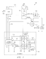
- Figure 1 is an electrical diagram of a generator powered electrically heated catalyst system, according to the preferred embodiment of the present invention.
- the present invention provides an electrical charging system that combines the proven features of conventional automotive charging systems with minimal extra circuitry to provide quick electrical heating of the catalytic converter to reduce exhaust emissions during critical cold start conditions.
- the prior art solution for quick-heating the catalytic converter is a chemical one with an air pump having decreased reliability and increased cost compared to the electrical technique of the present invention.
- FIG. 1 an electrical diagram of a Generator Powered Electrically Heated Catalyst System 100 , according to the present invention is shown.
- the electrical charging system represented by Generator Powered Electrically Heated Catalyst System 100 of Figure 1 may be an automotive electrical system or any other internal combustion system having a charging system.
- Junction Block Connection Point 101 is the common electrical system tie point usually located at the Starter Assembly Unit 105 , commonly on the starter solenoid. Junction Block Connection Point 101 can be on the Starter Assembly Unit 105 or typically may be located anywhere within the engine compartment.
- Battery 115 is the automobile DC battery.
- Electrical System Load 125 represents all the electrical circuits that normally load the vehicular electrical system.
- Generator 170 also known as an alternator, produces electrical power to charge the automotive electrical system in the usual manner, being excited by field current in Generator Rotor Field Winding 190 and being mechanically rotated by the operating engine.
- Generator 170 contains Generator Rotor Field Winding 190 , Generator Stator 180 , Rectifier Bridge 160 , and Regulator 150 .
- Generator Stator 180 contains Generator Stator Windings 121 which output three-phase electrical power to Rectifier Bridge 160 .
- the present embodiment illustrates Generator Stator Windings 121 as a delta winding; however, the invention is equally applicable to generators having Y-windings.
- Rectifier Bridge 160 contains six Rectifier Diodes 116 , and serves to transform the three-phase output of Generator Stator 180 to direct current (DC) which is then distributed to the automobile electrical system.
- Rectifier Bridge 160 The DC output of Rectifier Bridge 160 is routed to the switch common of Relay Single Pole Double Throw (SPDT) Switch Contacts 111 , and to Voltage Regulator Vgo Input 175 of Voltage Regulator 150 .
- Electrically Heated Catalyst Power Switch (EHC Switch) 110 contains an electrical relay, composed of Relay Coil 106 which controls the position of Relay SPDT Switch Contacts 111 .
- One output of Relay SPDT Switch Contacts 111 is routed to Junction Block Connection Point 101 , and is the current path normally found in automobile electrical systems.
- Relay SPDT Switch Contacts 111 The other output of Relay SPDT Switch Contacts 111 is routed to Electrically Heated Catalyst (EHC) 120 , and this is the path whereby Electrically Heated Catalyst 120 receives electrical power for catalytic converter quick heating.
- EHC Electrically Heated Catalyst
- Relay SPDT Switch Contacts 111 is connected through the normal path to Junction Block Connection Point 101 until the engine has started, and then is switched over to the Quick Heat path by Relay SPDT Switch Contacts 111 for a fixed time duration, such as approximately 30 seconds, sufficient to furnish heating power to the heating elements of Electrically Heated Catalyst 120 .
- Voltage Regulator 150 has four inputs and two outputs. The four inputs are Voltage Regulator Lamp Input 155 (L), Voltage Regulator Remote Sense Input 165 (S), Voltage Regulator Vgo Input 175 (the output voltage from Rectifier Bridge 160 ), and Voltage Regulator Phase Input 185 (P). The outputs of Voltage Regulator 150 are Voltage Regulator Field Output 195 (F+) and Voltage Regulator Field Monitor Input 145 (Fm). Voltage regulator Remote Sense Input 165 is utilized to monitor electrical system voltage in the usual manner, and is connected to Junction Block Connection Point 101 .
- Voltage Regulator Vgo Input 175 monitors the DC output of Rectifier Bridge 160 , being connected to the rectified output of Rectifier Bridge 160 , and also serves as the current source for regulator 150 and the Generator Rotor Field Winding 190 .
- Voltage Regulator Phase Input 185 receives the phase signal from Rectifier Bridge 160 , which is used by Voltage Regulator 150 to monitor possible failures internal to the combination of Rectifier Bridge 160 and Generator Stator 180 .
- Voltage Regulator Lamp Input 155 receives a signal from Control Module 130 , wherein Voltage Regulator Lamp Input 155 is utilized to control the on/off condition of Voltage Regulator 150 , as will be explained later.
- Voltage Regulator Field Monitor Output 145 is used for diagnostic purposes.
- Voltage Regulator Field Output 195 furnishes the current to excite Generator Rotor Field Winding 190 , and this excitation current combined with engine speed and Electrical System Load 125 current determines the output of Generator Stator Windings 121 , the DC voltage output by Rectifier Bridge 160 , and consequently the voltage present at Voltage Regulator Vgo Input 175 and the common terminal of Relay SPDT Switch Contacts 111 .
- a Control Module is capable of controlling both EHC Switch 110 and Voltage Regulator 150 as shown in Figure 1.
- the control module may take many forms, such as a conventional Engine Control Module (ECM) or an Electrically Heated Catalyst (EHC) control module.
- ECM Engine Control Module
- EHC Electrically Heated Catalyst
- the control module is a very complex, having a multitude of functions concerned with engines and the electronic control of engines but only a few ECM functions are utilized by the present invention.
- Control Module 130 provides three outputs utilized in the present invention. These outputs are Fault Output 140 , Switch Control Output 135 , and Voltage Regulator Lamp Input 155 .
- Fault Output 140 is used to indicate that a fault has occurred in the electrical charging system and depends upon design requirements of the system.
- Switch Control Output 135 is utilized to energize Relay Coil 106 to change the state of Relay SPDT Switch Contacts 111 .
- Voltage Regulator Lamp Input 155 is routed to input L of Voltage Regulator 150 , and this function has been previously discussed.
- Electrically Heated Catalyst 120 is the catalytic converter/heater assembly which is capable of being quickly heated when appropriate power is routed to it via the quick heat contact path through Relay SPDT Switch Contacts 111 .
- Control Module 130 reduces the regulation voltage setpoint of Voltage Regulator 150 by commanding Voltage Regulator Lamp Input 155 to a logic level low, thereby reducing engine load torque at engine start-up. Then Relay SPDT Switch Contacts 111 of Electrically Heated Catalyst Power Switch 110 disconnects the charging system (generator DC output) from the vehicle's electrical system (the path through Relay SPDT Switch Contacts 111 to Junction Block Connection Point 101 ), and connects the charging system to the heating elements within Electrically Heated Catalyst 120 . Control Module 130 then causes Voltage Regulator 150 to run at normal regulation by commanding Voltage Regulator Lamp Input 155 to a logic level high.
- An important aspect of the present invention is that the current through the Generator Rotor Field Winding 190 is delivered at the elevated output of Generator 170 and not at a lower setpoint regulation voltage or vehicle system voltage.
- This particular method of furnishing increased electrical power to Electrically Heated Catalyst 120 during quick heating was chosen because the characteristics of Generator 170 provide increased efficiency at elevated output voltages and high engine revolutions-per-minute (RPM), a condition which normally occurs during cold start high engine idle.
- RPM revolutions-per-minute
- Voltage Regulator Remote Sense Input 165 When Electrically Heated Catalyst Power Switch 110 is not activated and quick heating power is not being supplied to Electrically Heated Catalyst 120 , the sense input utilized by Voltage Regulator 150 is Voltage Regulator Remote Sense Input 165 . When Electrically Heated Catalyst Power Switch 110 is activated and quick heating power is supplied to Electrically Heated Catalyst 120 , the voltage at Voltage Regulator Remote Sense Input 165 drops below its previous value (the normal (or typical) charging system output will always exceed the voltage of a static Battery 115 ), causing the maximum output or overvoltage regulation condition previously discussed.
Landscapes
- Engineering & Computer Science (AREA)
- Chemical & Material Sciences (AREA)
- Chemical Kinetics & Catalysis (AREA)
- Combustion & Propulsion (AREA)
- Mechanical Engineering (AREA)
- General Engineering & Computer Science (AREA)
- Power Engineering (AREA)
- Health & Medical Sciences (AREA)
- Toxicology (AREA)
- Exhaust Gas After Treatment (AREA)
- Control Of Eletrric Generators (AREA)
Abstract
Description
Claims (19)
wherein when the engine of the electrical charging system is started, the switch is activated and the second output terminal of the relay switch contact of the switch is connected to the catalyst for a predetermined period of time to define a quick heating path that electrically heats the catalyst.
wherein when the engine of the electrical charging system is started, the switch is activated and the second output terminal of the relay switch contact of the switch is connected to the catalyst for a predetermined period of time to define a quick heating path that electrically heats the catalyst.
wherein when the engine of the electrical charging system is started, the catalyst power switch is activated and the second output terminal of the relay switch contact of the catalyst power switch is connected to the catalyst for a predetermined period of time to define a quick heating path that electrically heats the catalyst.
Applications Claiming Priority (2)
| Application Number | Priority Date | Filing Date | Title |
|---|---|---|---|
| US08/865,012 US6003304A (en) | 1997-05-29 | 1997-05-29 | Generator power electrically heated catalyst system |
| US865012 | 1997-05-29 |
Publications (2)
| Publication Number | Publication Date |
|---|---|
| EP0881738A2 true EP0881738A2 (en) | 1998-12-02 |
| EP0881738A3 EP0881738A3 (en) | 2000-06-28 |
Family
ID=25344529
Family Applications (1)
| Application Number | Title | Priority Date | Filing Date |
|---|---|---|---|
| EP98303804A Withdrawn EP0881738A3 (en) | 1997-05-29 | 1998-05-14 | Generator powered electrically heated catalyst system |
Country Status (3)
| Country | Link |
|---|---|
| US (1) | US6003304A (en) |
| EP (1) | EP0881738A3 (en) |
| JP (1) | JPH10331628A (en) |
Cited By (5)
| Publication number | Priority date | Publication date | Assignee | Title |
|---|---|---|---|---|
| EP1186476A3 (en) * | 2000-09-06 | 2006-06-28 | Mitsubishi Denki Kabushiki Kaisha | Electrical power supply system for a vehicle |
| EP2674340A1 (en) * | 2011-02-08 | 2013-12-18 | Toyota Jidosha Kabushiki Kaisha | Vehicle |
| CN108054977A (en) * | 2017-12-01 | 2018-05-18 | 中国商用飞机有限责任公司北京民用飞机技术研究中心 | Reduce the main Power feed electric power system and method for aircraft DC starting-generating |
| US10006462B2 (en) | 2012-09-18 | 2018-06-26 | Regal Beloit America, Inc. | Systems and method for wirelessly communicating with electric motors |
| CN109425479A (en) * | 2017-08-21 | 2019-03-05 | 阿里巴巴集团控股有限公司 | A kind of fault early warning method and device |
Families Citing this family (18)
| Publication number | Priority date | Publication date | Assignee | Title |
|---|---|---|---|---|
| US6321531B1 (en) * | 1996-12-18 | 2001-11-27 | Litex, Inc. | Method and apparatus for using free radicals to reduce pollutants in the exhaust gases from the combustion of a fuel |
| US6185932B1 (en) * | 1999-07-23 | 2001-02-13 | Sea C. Park | Quick-heating catalytic converter |
| IT1318017B1 (en) * | 2000-06-13 | 2003-07-21 | St Microelectronics Srl | RING REGULATION SYSTEM FOR A VOLTAGE, IN PARTICULAR FOR A VOLTAGE OF AN ELECTRIC SYSTEM IN A CAR. |
| US6418713B1 (en) * | 2000-12-08 | 2002-07-16 | Ford Global Technologies, Inc. | Method for generating additional engine loads during start-up |
| US6381955B1 (en) * | 2001-02-07 | 2002-05-07 | Visteon Global Technologies, Inc. | Method and system for providing electricity from an integrated starter-alternator to an electrically heated catalyst |
| US7007460B2 (en) * | 2003-08-11 | 2006-03-07 | General Motors Corporation | Apparatus and method for accelerated exhaust system component heating |
| DE102005002381A1 (en) * | 2005-01-18 | 2006-08-10 | Beru Ag | Method for operating a heating device for a motor vehicle |
| DE102006023275B3 (en) * | 2006-05-18 | 2007-04-26 | Dr.Ing.H.C. F. Porsche Ag | Method and device to adjust a required output voltage in a motor vehicle generator reduces the voltage if it exceeds a predetermined threshold and controls a cooling fan |
| US7990112B2 (en) * | 2008-08-14 | 2011-08-02 | Honeywell International Inc. | Adaptive field control of a variable frequency synchronous generator |
| US20100186373A1 (en) * | 2008-12-09 | 2010-07-29 | Patrick Pierz | Exhaust Heating for Gensets |
| US8322472B2 (en) * | 2009-05-04 | 2012-12-04 | GM Global Technology Operations LLC | Hybrid vehicle exhaust control strategy |
| CN102791554B (en) * | 2010-03-15 | 2014-12-10 | 丰田自动车株式会社 | Vehicle |
| WO2013166267A1 (en) * | 2012-05-02 | 2013-11-07 | Remy Technologies, Llc | Alternator with lockout mode |
| US8978239B2 (en) | 2013-01-09 | 2015-03-17 | General Electric Company | Field coil winding assembly |
| CN112654540A (en) * | 2018-10-31 | 2021-04-13 | 卡明斯公司 | Inverter-based exhaust aftertreatment thermal management apparatus, methods, systems, and techniques |
| DE102020132997A1 (en) * | 2020-12-10 | 2022-06-15 | Dr. Ing. H.C. F. Porsche Aktiengesellschaft | Power supply device |
| US11441463B1 (en) * | 2021-05-12 | 2022-09-13 | Ford Global Technologies, Llc | System and method for heating a catalyst |
| DE102021115045A1 (en) | 2021-06-10 | 2022-12-15 | Volkswagen Aktiengesellschaft | Process for heating up an electrically heated catalytic converter when idling |
Citations (4)
| Publication number | Priority date | Publication date | Assignee | Title |
|---|---|---|---|---|
| US5321231A (en) * | 1992-01-24 | 1994-06-14 | General Motors Corporation | System for supplying power to an electrically heated catalyst |
| US5325038A (en) * | 1991-06-10 | 1994-06-28 | Nippondenso Co., Ltd. | Driving apparatus for controlling an electric load in a vehicle |
| EP0763650A1 (en) * | 1995-09-13 | 1997-03-19 | Toyota Jidosha Kabushiki Kaisha | apparatus for controlling the supply of electric power to electrically heated catalyst |
| US5841266A (en) * | 1995-01-10 | 1998-11-24 | Hitachi Ltd. | Power source system for a vehicle |
Family Cites Families (4)
| Publication number | Priority date | Publication date | Assignee | Title |
|---|---|---|---|---|
| FR2645390B1 (en) * | 1989-03-31 | 1991-07-12 | Equip Electr Moteur | CONTROL SYSTEM FOR OVER-DEFROSTING AN ELECTRIC WINDSCREEN OF A MOTOR VEHICLE |
| US5645745A (en) * | 1994-09-02 | 1997-07-08 | Chrysler Corporation | Circuit and control method for electrically heating a catalyst |
| JPH08338234A (en) * | 1995-06-14 | 1996-12-24 | Toyota Motor Corp | Electric power feeder for heater for vehicle |
| JP3358405B2 (en) * | 1995-09-21 | 2002-12-16 | トヨタ自動車株式会社 | Control device for internal combustion engine equipped with electrically heated catalyst |
-
1997
- 1997-05-29 US US08/865,012 patent/US6003304A/en not_active Expired - Lifetime
-
1998
- 1998-05-14 EP EP98303804A patent/EP0881738A3/en not_active Withdrawn
- 1998-05-29 JP JP10148659A patent/JPH10331628A/en active Pending
Patent Citations (4)
| Publication number | Priority date | Publication date | Assignee | Title |
|---|---|---|---|---|
| US5325038A (en) * | 1991-06-10 | 1994-06-28 | Nippondenso Co., Ltd. | Driving apparatus for controlling an electric load in a vehicle |
| US5321231A (en) * | 1992-01-24 | 1994-06-14 | General Motors Corporation | System for supplying power to an electrically heated catalyst |
| US5841266A (en) * | 1995-01-10 | 1998-11-24 | Hitachi Ltd. | Power source system for a vehicle |
| EP0763650A1 (en) * | 1995-09-13 | 1997-03-19 | Toyota Jidosha Kabushiki Kaisha | apparatus for controlling the supply of electric power to electrically heated catalyst |
Cited By (9)
| Publication number | Priority date | Publication date | Assignee | Title |
|---|---|---|---|---|
| EP1186476A3 (en) * | 2000-09-06 | 2006-06-28 | Mitsubishi Denki Kabushiki Kaisha | Electrical power supply system for a vehicle |
| US7176659B2 (en) | 2000-09-06 | 2007-02-13 | Mitsubishi Denki Kabushiki Kaisha | Vehicle electrical power supply system for supplying power to a high power load |
| EP2674340A1 (en) * | 2011-02-08 | 2013-12-18 | Toyota Jidosha Kabushiki Kaisha | Vehicle |
| EP2674340A4 (en) * | 2011-02-08 | 2015-02-18 | Toyota Motor Co Ltd | Vehicle |
| US10006462B2 (en) | 2012-09-18 | 2018-06-26 | Regal Beloit America, Inc. | Systems and method for wirelessly communicating with electric motors |
| US10844861B2 (en) | 2012-09-18 | 2020-11-24 | Regal Beloit America, Inc. | Systems and method for wirelessly communicating with electric motors |
| CN109425479A (en) * | 2017-08-21 | 2019-03-05 | 阿里巴巴集团控股有限公司 | A kind of fault early warning method and device |
| CN108054977A (en) * | 2017-12-01 | 2018-05-18 | 中国商用飞机有限责任公司北京民用飞机技术研究中心 | Reduce the main Power feed electric power system and method for aircraft DC starting-generating |
| CN108054977B (en) * | 2017-12-01 | 2020-06-02 | 中国商用飞机有限责任公司北京民用飞机技术研究中心 | Main power feeder line power supply system and method for reducing direct current starting power generation of airplane |
Also Published As
| Publication number | Publication date |
|---|---|
| EP0881738A3 (en) | 2000-06-28 |
| JPH10331628A (en) | 1998-12-15 |
| US6003304A (en) | 1999-12-21 |
Similar Documents
| Publication | Publication Date | Title |
|---|---|---|
| US6003304A (en) | Generator power electrically heated catalyst system | |
| US5966931A (en) | Power supply control system for an electrically heated catalytic converter | |
| US6481406B2 (en) | Starter system and methods for starting an internal combustion engine | |
| US6904342B2 (en) | Control apparatus for energy storage device in motor vehicle | |
| US6218643B1 (en) | Power supplying apparatus for automotive part | |
| US6491121B2 (en) | Power-generating control apparatus for vehicle | |
| US5925938A (en) | Electrical system for a motor vehicle | |
| US5390493A (en) | Apparatus for controlling the electric heating of catalyst | |
| EP0647541A2 (en) | Control method for electrical appliance in hybrid vehicle | |
| US5404720A (en) | Alternator powered electrically heated catalyst | |
| US20050206350A1 (en) | Vehicle generator and vehicle generating system | |
| JP4119492B2 (en) | Generator control method | |
| USH1113H (en) | Apparatus for supplying power to electrically heated catalyst converter | |
| US7040269B2 (en) | Method for operating a drive with an internal combustion engine and an electric machine | |
| US7548042B2 (en) | DC-DC converter device and method for operating the dc-dc converter of a motor vehicle on-board electrical system | |
| KR20120073219A (en) | Method for controlling a micro-hybrid system | |
| EP0371472B1 (en) | Electrical system for automotive vehicle | |
| WO1992014631A1 (en) | Vehicle battery charging system | |
| JPH09151781A (en) | Power supply control device for vehicle | |
| US20110298277A1 (en) | Method for securing the operation of a voltage-holding device for a vehicle | |
| JP2910318B2 (en) | Power control device for catalyst with electric heater for vehicle | |
| JP3772930B2 (en) | SIGNAL ABNORMALITY DETECTING METHOD FOR VEHICLE AC GENERATOR, VOLTAGE CONTROL DEVICE AND VEHICLE CONTROL DEVICE | |
| KR100191995B1 (en) | Method and apparatus for controlling ehc in cars | |
| EP3875748B1 (en) | Vehicle power supply system | |
| JP2001157378A (en) | Voltage controlling device |
Legal Events
| Date | Code | Title | Description |
|---|---|---|---|
| PUAI | Public reference made under article 153(3) epc to a published international application that has entered the european phase |
Free format text: ORIGINAL CODE: 0009012 |
|
| AK | Designated contracting states |
Kind code of ref document: A2 Designated state(s): DE FR GB IT |
|
| AX | Request for extension of the european patent |
Free format text: AL;LT;LV;MK;RO;SI |
|
| RAP3 | Party data changed (applicant data changed or rights of an application transferred) |
Owner name: STMICROELECTRONICS, INC. |
|
| PUAL | Search report despatched |
Free format text: ORIGINAL CODE: 0009013 |
|
| AK | Designated contracting states |
Kind code of ref document: A3 Designated state(s): AT BE CH CY DE DK ES FI FR GB GR IE IT LI LU MC NL PT SE |
|
| AX | Request for extension of the european patent |
Free format text: AL;LT;LV;MK;RO;SI |
|
| 17P | Request for examination filed |
Effective date: 20001218 |
|
| AKX | Designation fees paid |
Free format text: DE FR GB IT |
|
| STAA | Information on the status of an ep patent application or granted ep patent |
Free format text: STATUS: THE APPLICATION HAS BEEN WITHDRAWN |
|
| 18W | Application withdrawn |
Effective date: 20070125 |