EP0881379A2 - Fuel-feed system for an engine - Google Patents
Fuel-feed system for an engine Download PDFInfo
- Publication number
- EP0881379A2 EP0881379A2 EP97120553A EP97120553A EP0881379A2 EP 0881379 A2 EP0881379 A2 EP 0881379A2 EP 97120553 A EP97120553 A EP 97120553A EP 97120553 A EP97120553 A EP 97120553A EP 0881379 A2 EP0881379 A2 EP 0881379A2
- Authority
- EP
- European Patent Office
- Prior art keywords
- fuel
- bellows
- chamber
- pressure
- return passage
- Prior art date
- Legal status (The legal status is an assumption and is not a legal conclusion. Google has not performed a legal analysis and makes no representation as to the accuracy of the status listed.)
- Granted
Links
Images


Classifications
-
- F—MECHANICAL ENGINEERING; LIGHTING; HEATING; WEAPONS; BLASTING
- F04—POSITIVE - DISPLACEMENT MACHINES FOR LIQUIDS; PUMPS FOR LIQUIDS OR ELASTIC FLUIDS
- F04B—POSITIVE-DISPLACEMENT MACHINES FOR LIQUIDS; PUMPS
- F04B11/00—Equalisation of pulses, e.g. by use of air vessels; Counteracting cavitation
- F04B11/0008—Equalisation of pulses, e.g. by use of air vessels; Counteracting cavitation using accumulators
- F04B11/0033—Equalisation of pulses, e.g. by use of air vessels; Counteracting cavitation using accumulators with a mechanical spring
-
- F—MECHANICAL ENGINEERING; LIGHTING; HEATING; WEAPONS; BLASTING
- F02—COMBUSTION ENGINES; HOT-GAS OR COMBUSTION-PRODUCT ENGINE PLANTS
- F02M—SUPPLYING COMBUSTION ENGINES IN GENERAL WITH COMBUSTIBLE MIXTURES OR CONSTITUENTS THEREOF
- F02M59/00—Pumps specially adapted for fuel-injection and not provided for in groups F02M39/00 -F02M57/00, e.g. rotary cylinder-block type of pumps
- F02M59/44—Details, components parts, or accessories not provided for in, or of interest apart from, the apparatus of groups F02M59/02 - F02M59/42; Pumps having transducers, e.g. to measure displacement of pump rack or piston
-
- F—MECHANICAL ENGINEERING; LIGHTING; HEATING; WEAPONS; BLASTING
- F02—COMBUSTION ENGINES; HOT-GAS OR COMBUSTION-PRODUCT ENGINE PLANTS
- F02M—SUPPLYING COMBUSTION ENGINES IN GENERAL WITH COMBUSTIBLE MIXTURES OR CONSTITUENTS THEREOF
- F02M55/00—Fuel-injection apparatus characterised by their fuel conduits or their venting means; Arrangements of conduits between fuel tank and pump F02M37/00
- F02M55/04—Means for damping vibrations or pressure fluctuations in injection pump inlets or outlets
-
- F—MECHANICAL ENGINEERING; LIGHTING; HEATING; WEAPONS; BLASTING
- F02—COMBUSTION ENGINES; HOT-GAS OR COMBUSTION-PRODUCT ENGINE PLANTS
- F02M—SUPPLYING COMBUSTION ENGINES IN GENERAL WITH COMBUSTIBLE MIXTURES OR CONSTITUENTS THEREOF
- F02M59/00—Pumps specially adapted for fuel-injection and not provided for in groups F02M39/00 -F02M57/00, e.g. rotary cylinder-block type of pumps
- F02M59/44—Details, components parts, or accessories not provided for in, or of interest apart from, the apparatus of groups F02M59/02 - F02M59/42; Pumps having transducers, e.g. to measure displacement of pump rack or piston
- F02M59/442—Details, components parts, or accessories not provided for in, or of interest apart from, the apparatus of groups F02M59/02 - F02M59/42; Pumps having transducers, e.g. to measure displacement of pump rack or piston means preventing fuel leakage around pump plunger, e.g. fluid barriers
-
- F—MECHANICAL ENGINEERING; LIGHTING; HEATING; WEAPONS; BLASTING
- F02—COMBUSTION ENGINES; HOT-GAS OR COMBUSTION-PRODUCT ENGINE PLANTS
- F02M—SUPPLYING COMBUSTION ENGINES IN GENERAL WITH COMBUSTIBLE MIXTURES OR CONSTITUENTS THEREOF
- F02M63/00—Other fuel-injection apparatus having pertinent characteristics not provided for in groups F02M39/00 - F02M57/00 or F02M67/00; Details, component parts, or accessories of fuel-injection apparatus, not provided for in, or of interest apart from, the apparatus of groups F02M39/00 - F02M61/00 or F02M67/00; Combination of fuel pump with other devices, e.g. lubricating oil pump
- F02M63/02—Fuel-injection apparatus having several injectors fed by a common pumping element, or having several pumping elements feeding a common injector; Fuel-injection apparatus having provisions for cutting-out pumps, pumping elements, or injectors; Fuel-injection apparatus having provisions for variably interconnecting pumping elements and injectors alternatively
- F02M63/0225—Fuel-injection apparatus having a common rail feeding several injectors ; Means for varying pressure in common rails; Pumps feeding common rails
-
- F—MECHANICAL ENGINEERING; LIGHTING; HEATING; WEAPONS; BLASTING
- F02—COMBUSTION ENGINES; HOT-GAS OR COMBUSTION-PRODUCT ENGINE PLANTS
- F02M—SUPPLYING COMBUSTION ENGINES IN GENERAL WITH COMBUSTIBLE MIXTURES OR CONSTITUENTS THEREOF
- F02M55/00—Fuel-injection apparatus characterised by their fuel conduits or their venting means; Arrangements of conduits between fuel tank and pump F02M37/00
- F02M55/007—Venting means
Abstract
Description
In the drawings:
Claims (10)
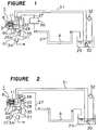
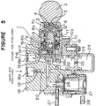
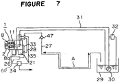
- A fuel-feed system for an engine comprising:a high-pressure fuel pump (1) including a driving member (2) to be rotated by an engine, a piston (8) reciprocatively driven by the driving member, a sleeve (9) for supporting the piston so as to carry out a reciprocating motion, the sleeve providing a pumping chamber, a housing (10) for supporting the sleeve so as to surround the sleeve, and bellows (11) having one end fixed to the piston and the other end fixed to housing, the bellows providing a bellows chamber for storing a fuel leaked from between the piston and the sleeve;a return passage (26, 27) for communicating the bellows of the pump and a fuel tank (29) to return the fuel stored in the bellows chamber to the fuel tank; andmeans (36, 38, 47, 47, 49) for restraining a variation in pressure of the fuel due to expansion and contraction of the bellows.
- A fuel-feed system for an engine according to Claim 1, wherein the means for restraining a variation in pressure of the fuel is a volume chamber (36) which is arranged in the return passage (27) and has a predetermined volume.
- A fuel-feed system for an engine according to Claim 2, wherein the volume in the volume chamber (36) is set so as to be larger than volume of the fuel which can stay in a portion (A) of the return passage (27) from the volume chamber to the fuel tank (29).
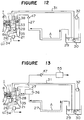
- A fuel-feed system for an engine according to Claim 1, wherein the means for restraining a variation in pressure of the fuel is a damper (38) which is arranged in at least one of the bellows chamber and the return passage (26, 27).
- A fuel-feed system for an engine according to Claim 4, wherein the damper (38) is arranged in a recess (10a) formed in the housing (10) which provides the bellows chamber.
- A fuel-feed system for an engine according to Claim 1, wherein the means for restraining a variation in pressure of the fuel is a check valve (47, 48, 49) which is arranged in the return passage (26, 27) and prevents the fuel from flowing back to the bellows chamber from a side of the fuel tank (29).
- A fuel-feed system for an engine according to Claim 6, wherein the check valve (48) is arranged in a reed valve (15) which provides an intake valve and a discharge valve of the pumping chamber of the high-pressure fuel pump (1) .
- A fuel-feed system for an engine according to any one of Claims 1-3, wherein the means for restraining a variation in pressure of the fuel is a combination of a volume chamber (36) which is arranged in the return passage (27) and has a predetermined volume, and a damper (38) which is arranged in at least one of the bellows chamber and the return passage (26).
- A fuel-feed system for an engine according to any one of Claims 1-3, wherein the means for restraining a variation in pressure of the fuel is a combination of a volume chamber (36) which is arranged in the return passage (27) and has a predetermined volume, and a check valve (47) which is arranged in the return passage (27) and prevents the fuel from flowing back to the bellows chamber from a side of the fuel tank (29).
- A fuel-feed system for an engine according to Claim 1, wherein the means for restraining a variation in pressure of the fuel is a combination of a damper (38) which is arranged in at least one of the bellows chamber and the return passage (26), and a check valve (47) which is arranged in the return passage (27) and prevents the fuel from flowing back to the bellows chamber from a side of the fuel tank (29).
Applications Claiming Priority (3)
| Application Number | Priority Date | Filing Date | Title |
|---|---|---|---|
| JP14212997 | 1997-05-30 | ||
| JP142129/97 | 1997-05-30 | ||
| JP14212997A JP3552464B2 (en) | 1997-05-30 | 1997-05-30 | Engine fuel supply |
Publications (3)
| Publication Number | Publication Date |
|---|---|
| EP0881379A2 true EP0881379A2 (en) | 1998-12-02 |
| EP0881379A3 EP0881379A3 (en) | 1999-07-21 |
| EP0881379B1 EP0881379B1 (en) | 2003-07-02 |
Family
ID=15308059
Family Applications (1)
| Application Number | Title | Priority Date | Filing Date |
|---|---|---|---|
| EP97120553A Expired - Lifetime EP0881379B1 (en) | 1997-05-30 | 1997-11-24 | Fuel-feed system for an engine |
Country Status (7)
| Country | Link |
|---|---|
| US (1) | US5832904A (en) |
| EP (1) | EP0881379B1 (en) |
| JP (1) | JP3552464B2 (en) |
| KR (1) | KR100306531B1 (en) |
| CN (1) | CN1070996C (en) |
| DE (1) | DE69723233T2 (en) |
| TW (1) | TW403814B (en) |
Families Citing this family (14)
| Publication number | Priority date | Publication date | Assignee | Title |
|---|---|---|---|---|
| JP2922489B1 (en) * | 1998-02-13 | 1999-07-26 | 三菱電機株式会社 | Piston type high pressure fuel pump filter |
| JPH11247742A (en) * | 1998-03-02 | 1999-09-14 | Zexel:Kk | Plunger pump |
| US6036448A (en) * | 1998-09-11 | 2000-03-14 | Chrysler Corporation | Fuel pump sealed in a bellows |
| JP3633314B2 (en) * | 1998-10-14 | 2005-03-30 | 三菱電機株式会社 | High pressure fuel pump device |
| JP2000291509A (en) * | 1999-04-01 | 2000-10-17 | Mitsubishi Electric Corp | Fuel supply device for direct injection type gasoline engine |
| JP2001055961A (en) * | 1999-08-11 | 2001-02-27 | Mitsubishi Electric Corp | High pressure fuel supplying device |
| JP2001059466A (en) | 1999-08-20 | 2001-03-06 | Mitsubishi Electric Corp | High pressure fuel pump |
| US6230685B1 (en) * | 1999-11-12 | 2001-05-15 | Siemens Automotive Corporation | Pressure pulsation damper containing a free floating spacer |
| JP4840342B2 (en) * | 2007-11-30 | 2011-12-21 | 三菱電機株式会社 | Vehicle fuel supply system |
| JP5530276B2 (en) * | 2010-07-08 | 2014-06-25 | ホクシン産業株式会社 | Fuel oil transfer device |
| DE102011008467B4 (en) * | 2011-01-13 | 2014-01-02 | Continental Automotive Gmbh | Injector with pressure compensation |
| ITBO20110183A1 (en) * | 2011-04-07 | 2012-10-08 | Magneti Marelli Spa | SILENCED FUEL PUMP FOR A DIRECT INJECTION SYSTEM |
| CN103161633A (en) * | 2011-12-14 | 2013-06-19 | 中国第一汽车股份有限公司无锡油泵油嘴研究所 | High-pressure fuel feeding pump |
| EP3037294B1 (en) * | 2014-12-25 | 2019-05-01 | Toyota Jidosha Kabushiki Kaisha | Pressure control apparatus of fuel tank for vehicle |
Family Cites Families (14)
| Publication number | Priority date | Publication date | Assignee | Title |
|---|---|---|---|---|
| US2512025A (en) * | 1948-04-17 | 1950-06-20 | Borg Warner | Pump-gear and piston combination with unloading |
| US2665641A (en) * | 1949-06-18 | 1954-01-12 | Borg Warner | Pump, pressure loaded, with differential valve |
| US3806283A (en) * | 1973-01-04 | 1974-04-23 | Int Standard Electric Corp | Pump by-pass |
| CH615731A5 (en) * | 1976-06-11 | 1980-02-15 | Sulzer Ag | |
| US4597322A (en) * | 1984-01-09 | 1986-07-01 | Moog Inc. | Seal assemblies |
| JPH0712029A (en) * | 1993-06-24 | 1995-01-17 | Mitsubishi Electric Corp | High pressure fuel pump |
| DE4330855C1 (en) * | 1993-09-11 | 1994-10-13 | Technoflow Tube Systems Gmbh | Use of a plastics pipe as a crash-protected motor-vehicle fuel line |
| US5474050A (en) * | 1995-01-13 | 1995-12-12 | Siemens Electric Limited | Leak detection pump with integral vent seal |
| JP3760486B2 (en) * | 1995-08-30 | 2006-03-29 | 日産自動車株式会社 | Fuel pump |
| JPH09250427A (en) * | 1996-03-15 | 1997-09-22 | Zexel Corp | Fuel injection pump |
| JP3492880B2 (en) * | 1996-04-16 | 2004-02-03 | 日本電信電話株式会社 | Thin film formation method |
| US5682861A (en) * | 1996-05-23 | 1997-11-04 | Caterpillar Inc. | Fluid seal for cyclic high pressures within a fuel injection |
| JPH10176625A (en) * | 1996-12-19 | 1998-06-30 | Unisia Jecs Corp | Plunger pump |
| JPH10318123A (en) * | 1997-05-19 | 1998-12-02 | Honda Motor Co Ltd | High pressure fuel pump |
-
1997
- 1997-05-30 JP JP14212997A patent/JP3552464B2/en not_active Expired - Lifetime
- 1997-11-20 US US08/974,885 patent/US5832904A/en not_active Expired - Lifetime
- 1997-11-24 EP EP97120553A patent/EP0881379B1/en not_active Expired - Lifetime
- 1997-11-24 DE DE69723233T patent/DE69723233T2/en not_active Expired - Lifetime
- 1997-12-23 KR KR1019970072207A patent/KR100306531B1/en not_active IP Right Cessation
-
1998
- 1998-01-13 CN CN98103620A patent/CN1070996C/en not_active Expired - Fee Related
- 1998-01-26 TW TW087101027A patent/TW403814B/en not_active IP Right Cessation
Non-Patent Citations (1)
| Title |
|---|
| None |
Also Published As
| Publication number | Publication date |
|---|---|
| JP3552464B2 (en) | 2004-08-11 |
| EP0881379A3 (en) | 1999-07-21 |
| KR19980086467A (en) | 1998-12-05 |
| DE69723233D1 (en) | 2003-08-07 |
| CN1070996C (en) | 2001-09-12 |
| JPH10331735A (en) | 1998-12-15 |
| US5832904A (en) | 1998-11-10 |
| TW403814B (en) | 2000-09-01 |
| EP0881379B1 (en) | 2003-07-02 |
| KR100306531B1 (en) | 2001-12-17 |
| DE69723233T2 (en) | 2004-04-15 |
| CN1201109A (en) | 1998-12-09 |
Similar Documents
| Publication | Publication Date | Title |
|---|---|---|
| US5832904A (en) | Fuel-feed system for an engine | |
| US7513240B2 (en) | High pressure fuel pump provided with damper | |
| US6053712A (en) | Cylinder injection high-pressure fuel pump | |
| JP4736142B2 (en) | High pressure pump | |
| US6079450A (en) | Metal diaphragm type pulsation absorber for high-pressure fuel pump | |
| JP4941688B2 (en) | High pressure pump | |
| US20030161746A1 (en) | High-pressure fuel pump and assembly structure of high-pressure pump | |
| JP3391202B2 (en) | Evaporative fuel control system for internal combustion engine | |
| US7178512B1 (en) | Fuel system for a marine vessel with a gaseous purge fuel container | |
| US7128541B2 (en) | Oscillating displacement pump | |
| US6634343B2 (en) | Evaported fuel processor and fault diagnosing apparatus therefor | |
| US4589395A (en) | Fuel system for internal combustion engines | |
| US6155235A (en) | Pressure pulsation damper with integrated hot soak pressure control valve | |
| US4778357A (en) | Shut-off valve for an electromagnetic pump | |
| KR100370854B1 (en) | Fuel supply apparatus | |
| EP1045134A2 (en) | Carburetor with vapor purge pump | |
| KR102108164B1 (en) | High pressure pump | |
| WO2003062627A1 (en) | Fuel feeder | |
| JP2000249018A (en) | Metal bellows type pulsation absorbing device | |
| JP3782727B2 (en) | Electromagnetic pump | |
| JP3563277B2 (en) | Fuel supply device for internal combustion engine | |
| JPS6120359Y2 (en) | ||
| JPH0811489B2 (en) | Fuel tank | |
| JPH0124370Y2 (en) | ||
| JPS6024934Y2 (en) | automotive fuel filter |
Legal Events
| Date | Code | Title | Description |
|---|---|---|---|
| PUAI | Public reference made under article 153(3) epc to a published international application that has entered the european phase |
Free format text: ORIGINAL CODE: 0009012 |
|
| AK | Designated contracting states |
Kind code of ref document: A2 Designated state(s): DE FR GB IT |
|
| AX | Request for extension of the european patent |
Free format text: AL;LT;LV;MK;RO;SI |
|
| PUAL | Search report despatched |
Free format text: ORIGINAL CODE: 0009013 |
|
| AK | Designated contracting states |
Kind code of ref document: A3 Designated state(s): AT BE CH DE DK ES FI FR GB GR IE IT LI LU MC NL PT SE |
|
| AX | Request for extension of the european patent |
Free format text: AL;LT;LV;MK;RO;SI |
|
| 17P | Request for examination filed |
Effective date: 19990721 |
|
| AKX | Designation fees paid |
Free format text: DE FR GB IT |
|
| 17Q | First examination report despatched |
Effective date: 20010906 |
|
| GRAH | Despatch of communication of intention to grant a patent |
Free format text: ORIGINAL CODE: EPIDOS IGRA |
|
| GRAH | Despatch of communication of intention to grant a patent |
Free format text: ORIGINAL CODE: EPIDOS IGRA |
|
| GRAA | (expected) grant |
Free format text: ORIGINAL CODE: 0009210 |
|
| AK | Designated contracting states |
Designated state(s): DE FR GB IT |
|
| REG | Reference to a national code |
Ref country code: GB Ref legal event code: FG4D |
|
| REF | Corresponds to: |
Ref document number: 69723233 Country of ref document: DE Date of ref document: 20030807 Kind code of ref document: P |
|
| ET | Fr: translation filed | ||
| PLBE | No opposition filed within time limit |
Free format text: ORIGINAL CODE: 0009261 |
|
| STAA | Information on the status of an ep patent application or granted ep patent |
Free format text: STATUS: NO OPPOSITION FILED WITHIN TIME LIMIT |
|
| 26N | No opposition filed |
Effective date: 20040405 |
|
| PGFP | Annual fee paid to national office [announced via postgrant information from national office to epo] |
Ref country code: IT Payment date: 20081127 Year of fee payment: 12 |
|
| PGFP | Annual fee paid to national office [announced via postgrant information from national office to epo] |
Ref country code: FR Payment date: 20081112 Year of fee payment: 12 |
|
| PGFP | Annual fee paid to national office [announced via postgrant information from national office to epo] |
Ref country code: GB Payment date: 20081119 Year of fee payment: 12 |
|
| GBPC | Gb: european patent ceased through non-payment of renewal fee |
Effective date: 20091124 |
|
| REG | Reference to a national code |
Ref country code: FR Ref legal event code: ST Effective date: 20100730 |
|
| PG25 | Lapsed in a contracting state [announced via postgrant information from national office to epo] |
Ref country code: FR Free format text: LAPSE BECAUSE OF NON-PAYMENT OF DUE FEES Effective date: 20091130 |
|
| PG25 | Lapsed in a contracting state [announced via postgrant information from national office to epo] |
Ref country code: GB Free format text: LAPSE BECAUSE OF NON-PAYMENT OF DUE FEES Effective date: 20091124 |
|
| PG25 | Lapsed in a contracting state [announced via postgrant information from national office to epo] |
Ref country code: IT Free format text: LAPSE BECAUSE OF NON-PAYMENT OF DUE FEES Effective date: 20091124 |
|
| PGFP | Annual fee paid to national office [announced via postgrant information from national office to epo] |
Ref country code: DE Payment date: 20161116 Year of fee payment: 20 |
|
| REG | Reference to a national code |
Ref country code: DE Ref legal event code: R071 Ref document number: 69723233 Country of ref document: DE |