EP0880809B1 - Insertion tool and method of use - Google Patents
Insertion tool and method of use Download PDFInfo
- Publication number
- EP0880809B1 EP0880809B1 EP97903122A EP97903122A EP0880809B1 EP 0880809 B1 EP0880809 B1 EP 0880809B1 EP 97903122 A EP97903122 A EP 97903122A EP 97903122 A EP97903122 A EP 97903122A EP 0880809 B1 EP0880809 B1 EP 0880809B1
- Authority
- EP
- European Patent Office
- Prior art keywords
- connection device
- contact
- tool
- fixture base
- channel
- Prior art date
- Legal status (The legal status is an assumption and is not a legal conclusion. Google has not performed a legal analysis and makes no representation as to the accuracy of the status listed.)
- Expired - Lifetime
Links
Images

Classifications
-
- H—ELECTRICITY
- H01—ELECTRIC ELEMENTS
- H01R—ELECTRICALLY-CONDUCTIVE CONNECTIONS; STRUCTURAL ASSOCIATIONS OF A PLURALITY OF MUTUALLY-INSULATED ELECTRICAL CONNECTING ELEMENTS; COUPLING DEVICES; CURRENT COLLECTORS
- H01R43/00—Apparatus or processes specially adapted for manufacturing, assembling, maintaining, or repairing of line connectors or current collectors or for joining electric conductors
- H01R43/20—Apparatus or processes specially adapted for manufacturing, assembling, maintaining, or repairing of line connectors or current collectors or for joining electric conductors for assembling or disassembling contact members with insulating base, case or sleeve
- H01R43/22—Hand tools
-
- G—PHYSICS
- G02—OPTICS
- G02B—OPTICAL ELEMENTS, SYSTEMS OR APPARATUS
- G02B6/00—Light guides; Structural details of arrangements comprising light guides and other optical elements, e.g. couplings
- G02B6/24—Coupling light guides
- G02B6/36—Mechanical coupling means
- G02B6/38—Mechanical coupling means having fibre to fibre mating means
- G02B6/3807—Dismountable connectors, i.e. comprising plugs
- G02B6/3898—Tools, e.g. handheld; Tuning wrenches; Jigs used with connectors, e.g. for extracting, removing or inserting in a panel, for engaging or coupling connectors, for assembling or disassembling components within the connector, for applying clips to hold two connectors together or for crimping
-
- H—ELECTRICITY
- H01—ELECTRIC ELEMENTS
- H01R—ELECTRICALLY-CONDUCTIVE CONNECTIONS; STRUCTURAL ASSOCIATIONS OF A PLURALITY OF MUTUALLY-INSULATED ELECTRICAL CONNECTING ELEMENTS; COUPLING DEVICES; CURRENT COLLECTORS
- H01R13/00—Details of coupling devices of the kinds covered by groups H01R12/70 or H01R24/00 - H01R33/00
- H01R13/40—Securing contact members in or to a base or case; Insulating of contact members
- H01R13/42—Securing in a demountable manner
- H01R13/426—Securing by a separate resilient retaining piece supported by base or case, e.g. collar or metal contact-retention clip
-
- Y—GENERAL TAGGING OF NEW TECHNOLOGICAL DEVELOPMENTS; GENERAL TAGGING OF CROSS-SECTIONAL TECHNOLOGIES SPANNING OVER SEVERAL SECTIONS OF THE IPC; TECHNICAL SUBJECTS COVERED BY FORMER USPC CROSS-REFERENCE ART COLLECTIONS [XRACs] AND DIGESTS
- Y10—TECHNICAL SUBJECTS COVERED BY FORMER USPC
- Y10T—TECHNICAL SUBJECTS COVERED BY FORMER US CLASSIFICATION
- Y10T29/00—Metal working
- Y10T29/49—Method of mechanical manufacture
- Y10T29/49002—Electrical device making
- Y10T29/49117—Conductor or circuit manufacturing
- Y10T29/49124—On flat or curved insulated base, e.g., printed circuit, etc.
- Y10T29/49147—Assembling terminal to base
- Y10T29/49151—Assembling terminal to base by deforming or shaping
- Y10T29/49153—Assembling terminal to base by deforming or shaping with shaping or forcing terminal into base aperture
-
- Y—GENERAL TAGGING OF NEW TECHNOLOGICAL DEVELOPMENTS; GENERAL TAGGING OF CROSS-SECTIONAL TECHNOLOGIES SPANNING OVER SEVERAL SECTIONS OF THE IPC; TECHNICAL SUBJECTS COVERED BY FORMER USPC CROSS-REFERENCE ART COLLECTIONS [XRACs] AND DIGESTS
- Y10—TECHNICAL SUBJECTS COVERED BY FORMER USPC
- Y10T—TECHNICAL SUBJECTS COVERED BY FORMER US CLASSIFICATION
- Y10T29/00—Metal working
- Y10T29/49—Method of mechanical manufacture
- Y10T29/49002—Electrical device making
- Y10T29/49117—Conductor or circuit manufacturing
- Y10T29/49204—Contact or terminal manufacturing
- Y10T29/49208—Contact or terminal manufacturing by assembling plural parts
-
- Y—GENERAL TAGGING OF NEW TECHNOLOGICAL DEVELOPMENTS; GENERAL TAGGING OF CROSS-SECTIONAL TECHNOLOGIES SPANNING OVER SEVERAL SECTIONS OF THE IPC; TECHNICAL SUBJECTS COVERED BY FORMER USPC CROSS-REFERENCE ART COLLECTIONS [XRACs] AND DIGESTS
- Y10—TECHNICAL SUBJECTS COVERED BY FORMER USPC
- Y10T—TECHNICAL SUBJECTS COVERED BY FORMER US CLASSIFICATION
- Y10T29/00—Metal working
- Y10T29/53—Means to assemble or disassemble
- Y10T29/5313—Means to assemble electrical device
- Y10T29/532—Conductor
- Y10T29/53209—Terminal or connector
-
- Y—GENERAL TAGGING OF NEW TECHNOLOGICAL DEVELOPMENTS; GENERAL TAGGING OF CROSS-SECTIONAL TECHNOLOGIES SPANNING OVER SEVERAL SECTIONS OF THE IPC; TECHNICAL SUBJECTS COVERED BY FORMER USPC CROSS-REFERENCE ART COLLECTIONS [XRACs] AND DIGESTS
- Y10—TECHNICAL SUBJECTS COVERED BY FORMER USPC
- Y10T—TECHNICAL SUBJECTS COVERED BY FORMER US CLASSIFICATION
- Y10T29/00—Metal working
- Y10T29/53—Means to assemble or disassemble
- Y10T29/5313—Means to assemble electrical device
- Y10T29/53261—Means to align and advance work part
Definitions
- This invention relates to a tool for inserting a contact into a connection device and a method of using the tool.
- This tool is particularly useful for inserting a substrate having a contact into the connection device described in U.S. Patent Application US-A-5,824,954.
- Such tool for inserting a contact into a connection device and a method of using such a tool are known from US-A-4.907.470, US-A-5.355.583 and US-A-5.528.821.
- US-A-5.528.821 discloses a tool for inserting a contact into a connection device comprising :
- Wire splicing in automotive electrical harnesses is typically done by crimping or welding wires to be spliced and then covering the joint to insulate and seal. Splicing operations are generally considered to be craft sensitive and, therefore, difficult to control. It is, however, desirable to provide consistent splicing and to ensure that the contact is fully connected to the electrical element and cannot be easily separated therefrom.
- connection device as described in U.S. Patent Application US-A-5,824,954 it may be difficult to properly insert the contact into the connection device because there is no efficient way to hold the substrate close enough to the contact so as to ensure that the contact is fully inserted into the connection device and connected to the electrical element. It is also desirable to provide consistent results. Many substrates, such as wires with small diameters, do not have sufficient rigidity to be capable of holding them the required distance from the contact and still be able to exert an insertion force for proper insertion into the connection device without buckling of the substrate.
- the tool of the present invention avoids exerting an insertion force on the substrate, which might cause the substrate to buckle.
- this tool may be used with any size substrate and contact, but is particularly useful for wires or fiber optic cables having small diameters.
- the tool is designed to ensure that the contact is properly inserted into the connection device and placement of the contact is not sensitive to craftsmanship.
- a first aspect of the invention comprises a method for connecting a substrate having a contact disposed at a distal end of the substrate to a connection device, the method comprising:
- a second aspect of the invention comprises a tool for connecting a substrate having a contact disposed at a distal end of the substrate to a connection device, said tool comprising:
- a further aspect of the invention comprises a kit of parts containing:
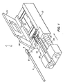
- Figs. 1 and 2 illustrate an insertion tool 2 for connecting a substrate 4 having a contact 6 disposed at a distal end 8 of the substrate to a connection device 10.
- the body of insertion tool 2 is in the form of a fixture base 12.
- Substrate 4 may be any elongate element which is to be inserted into a connection device.
- the substrate may be a wire or optical fiber cable, particularly one having a small diameter which would normally buckle when subjected to an insertion force sufficient to insert the contact into the connection device.
- Contact 6 is affixed to distal end 8 of substrate 4.
- One side of contact 6 protrudes radially outward from the longitudinal axis of the substrate, forming a proximal radial edge 22, as seen in Figs. 1 and 2, the purpose of which is described below.
- Fixture base 12 includes a cavity 14 for receiving connection device 10 in proper position and orientation.
- Cavity 14 is sized such that connection device 10 fits within the cavity, including depressions and protrusions (not shown) which conform to the shape of complementary protrusions and depressions of the connection device.
- Fixture base 12 also includes a channel 16 communicating with cavity 14 for guiding substrate 4 and contact 6 into the connection device.
- Channel 16 is sized such that contact 6 fits therein in proper position and orientation.
- fixture base 12 includes a plurality of channels 16 for simultaneously inserting a plurality of substrates into a connection device.
- a pusher arm 18 is employed to insert contact 6 into connection device 10.
- Pusher arm 18 is elongate and slides through channel 16 into cavity 14.
- the distal end of pusher arm 18 is raised slightly to form a lip 20, as shown in Figs. 1 and 2, for engaging proximal radial edge 22 of contact 6 for exerting a force on the contact and inserting it into connection device 10.
- Pusher arm 18 extends into the proximal end of channel 16.
- the pusher arm is configured such that each channel 16 has a corresponding lip 20 for engaging the contact in that channel.
- connection device cover 24 retains connection device 10 in cavity 14 and establishes that connection device 10 is in its proper position and orientation.
- Connection device cover 24 is movable with respect to fixture base 12 and has a lock for retaining the connection device cover on the fixture base.
- Connection device cover 24 may be hinged to fixture base 12, as shown in Fig. 1, slidable on the fixture base, or removable from the fixture base.
- the lock may be a snap fit connection, or any other positive connection between the connection device cover and the fixture base. Because of the cooperation of the depressions and protrusions of the cavity and connection device, the connection device will properly fit into the cavity only if it is in proper position and orientation. Thus, the connection device cover is incapable of locking to the fixture base when the connection device is improperly received in the cavity.
- a contact cover 26 retains contact 6 in channel 16 and establishes that the contact is in its proper position and orientation.
- Contact cover 26 is movable with respect to fixture base 12 and has a lock for retaining the contact cover on the fixture base.
- Contact cover 26 may be hinged to fixture base 12, as shown in Fig. 1, slidable on the fixture base, or removable from the fixture base.
- the lock may be a snap fit connection, or or any other positive connection between the contact cover and the fixture base. Because the contact is configured to protrude radially from one side of substrate 4 (as discussed above) and pusher arm includes a raised lip 20, proximal radial edge 22 fits into channel 16 with the proximal radial edge extending downwardly, distally of the pusher arm.
- Connection device cover 24 and contact cover 26 may be separate elements, as shown in the drawings, or may be a single cover, securing both the connection device and contact.
- Pusher arm 18 is designed such that it cannot begin to slide and advance into cavity 14 unless covers 24, 26 are closed and locked in place. Additionally, the pusher arm may be designed such that it cannot return to its initial position unless it has been fully advanced.
- Alignment means acting with fixture base 12 and pusher arm 18 maintains alignment between the fixture base and pusher arm.
- the alignment means may have any acceptable configuration.
- the alignment means is in the form of at least one axial rod 28, and more preferably two axial rods 28, 29, slidable relative to one of the pusher arm and fixture base so that as the pusher arm is moved through channel 16 and into cavity 14.
- the axial rod or rods ensure that the force of the pusher arm is directed so as to insert the contact into the connection device.
- the axial rod is attached to fixture base 12, however, it is within the scope of the present invention to construct insertion tool 2 with an axial rod connected to the pusher arm and slidable into the fixture base.
- Biasing means 30 biases the pusher arm in the proximal direction through channel 16 and out of cavity 14.
- the biasing means comprises a spring, more preferably a coil spring, positioned between the fixture base and the pusher arm. It should be noted that any type of biasing means which would urge the fixture base and pusher arm apart may be employed, for example, air or hydraulic pressure.
- a contact test circuit may be included on insertion tool 2 to test the circuit and ensure that the substrate to be inserted into connection device 10 is the desired substrate.
- Connection device 10 may be a sealed interconnection device as described in U.S. Patent US-A-5.824.954 but the connection device need not be a sealed device.
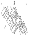
- Connection device 10 is shown in detail in Fig. 3.
- Connection device 10 includes a body 32 and an electrical element 34.
- Body 32 comprises a first section 36 and a second section 38 bonded together along edges 40, 42 to form an enclosure 44 having an open edge 46.
- Enclosure 44 includes passageways 48 extending from open edge 46 for receiving substrate 4, to a retaining portion 50 of the enclosure.
- Electrical element 34 is retained within enclosure 44 in retaining portion 50.
- a sealing member 52 may be located in enclosure 44 adjacent open edge 46, at the opposite end of passageways 48 from the electrical element. It should be noted that the connection device used in conjunction with the present invention need not be sealed.
- Sections 36, 38 are preferably constructed of multiple layers of polymeric film, more preferably expanded film bonded together to form enclosure 44. It should be noted, however, that sections 36, 38 may be a variety of constructions, for example, formed, molded or extruded parts. Prior to securing sections 36, 38 together, electrical element 34 and sealing member 52, if present, are inserted into enclosure 44 so as to be enclosed therein when the sections are secured together. In the preferred embodiment, sections 36, 38 are mirror images of each other, together forming enclosure 44, including passageways 48 and retaining section 50.
- open edge 46 preferably has a configuration such that at least one dimension is smaller than a corresponding dimension of electrical element 34. In this way, the electrical element is retained within enclosure 44.
- connection device 10 has more than one open edge through which substrates may be inserted for connection to the electrical element as seen in Figs. 2 and 3; however, only one edge may be open for receiving substrates.
- Electrical element 34 may be any electrical joining device, such as a splice, a ground, a circuit protection device, a printed circuit device, or any of a number of electrical elements for which it is desirable to connect substrates thereto. Electrical element 34 is placed in retaining portion 50 prior to securing sections 36, 38 together, as discussed above. The configuration of electrical element 34, enclosure 44 and retaining portion 50 are such that once sections 36, 38 are secured together, the electrical element cannot be removed from the enclosure.
- Electrical element 34 is preferably relatively flat when connection device 10 has only a first and second section; however, body 32 may be constructed of more than two sections, such that the electrical element may have a more three dimensional configuration. Additionally, multiple electrical elements may be included in enclosure 44. Multiple electrical elements may or may not be isolated from every other electrical element.
- a locking means may be employed for locking substrates into connection device 10.
- Locking means is preferably a locking element 54 captivated between passageways 48 and electrical element 34 such that when contact 6 is inserted therethrough, the contact cannot be easily removed.
- the element is constructed such that portions 56 of the locking element are forced apart and, once the contact is fully inserted, portions 56 of the locking element return to their original configuration preventing proximal radial edge 22 from returning through locking element portions 56, resulting in a detent action which locks the contact in place.
- Locking element portions 56 are described herein as being a separate mechanical element, however, the locking element portions could be formed as part of body sections 36, 38. Additionally, any locking means may be employed in the present invention, including heat deformation of a portion the body.
- connection device 10 is inserted and located in cavity 14 of insertion tool 2 in proper position and orientation, as described above.
- Connection device cover 24 is closed to ensure that connection device 10 is retained in proper position and orientation.
- One or more contacts 6 is inserted into channels 16 in proper position and orientation, with proximal radial edge 20 extending downwardly, distally of pusher arm 18. No more than one contact is inserted into each channel.
- Contact cover 26 is closed to ensure that contact 6 is retained in proper position and orientation.
- Insertion tool 2 may be a manual hand tool which may include a handle, or may be automated, for example, with air, hydraulic or electric activation. Actuation of insertion tool 2 slides pusher arm 18, forcing contact 6 in a distal direction into connection device 10. As it slides, contact 6 enters into locking element 54 and is locked in place. Pusher arm 18 enters the connection device with contact 6 and, if sealing member 52 is present, through the member. Biasing means 30 biases pusher arm 18 in the proximal direction out of the connection device and cavity, through channel 16 and is thereby removed from the connection device.
- the present invention thus connects substrates to the connection device by exerting a force on the contact rather than the substrate, thus the strength and rigidity of the substrate is not a factor in connecting the contact to the connection device.
Landscapes
- Engineering & Computer Science (AREA)
- Manufacturing & Machinery (AREA)
- Manufacturing Of Electrical Connectors (AREA)
Description
- a fixure base having a cavity for receiving the connection device in proper position and orientation within the cavity;
- a pusher arm for engaging the contact; and
- a means for sliding the pusher arm with respect to the fixure base.
Claims (20)
- A method for connecting a substrate (4) having a contact (6) disposed at a distal end (8) of the substrate to a connection device (10), the method comprising:a) locating the connection device (10) in proper position and orientation within a cavity (14) of a fixture base (12);b) locating the contact (6) in proper position and orientation within a channel (16) of the fixture base (12), the channel (16) communicating with the cavity (14);c) engaging a proximal edge (22) of the contact (6) with a pusher arm (18); andd) sliding the pusher arm (18) with respect to the fixture base (12) so as to move the contact through the channel (16) and thereby insert the contact (6) into the connection device.
- The method as defined in claim 1 wherein in step (d) the pusher arm (18) enters the connection device (10).
- The method as defined in claim 2 further comprising the step of removing the pusher arm (18) from the connection device (10).
- The method as defined in claim 1 wherein step (d) further comprises locking the contact (6) into the connection device (10).
- The method as defined in claim 1 wherein a plurality of contacts (6) are simultaneously inserted into the connection device (10).
- The method as defined in claim 1 further comprising the step of establishing that the connection device (10) is in its proper position and orientation and retaining the connection device (10) in position and orientation.
- The method as defined in claim 1 further comprising the step of establishing that the contact (6) is in its proper position and orientation and retaining the contact (6) in position and orientation.
- A tool (2) for connecting a substrate (4) having a contact (6) disposed at a distal end of the substrate (4) to a connection device (10), said tool comprising:a fixture base (12) having a cavity (14) for receiving the connection device (10) in proper position and orientation within the cavity (14);a channel (16) within the fixure base (12) for guiding the substrate (4) and contact (6) for insertion into the connection device (10), the channel communicating with the cavity (14);a pusher arm (18) for engaging a proximal edge (22) of the contact (6); andmeans for sliding (30) the pusher arm (18) with respect to the fixture base (12) so as to slide the contact (6) through the channel (16) and thereby insert the contact (6) into the connection device (10).
- The tool (2) as defined in claim 8 further comprising first means for establishing (24) that the connection device (10) is in proper position and orientation in said cavity (14).
- The tool (2) as defined in claim 9 wherein said first means for establishing comprises a first connection device cover (24) movable with respect to said fixture base (12) and having a lock for locking the first connection device cover (24) to said fixture base (12), said first connection device cover (24) being incapable of locking to said fixture base when said connection device is improperly received in said cavity (14).
- The tool (2) as defined in claim 8 further comprising second means for establishing (26) that the contact (6) is in proper position and orientation in said channel (16).
- The tool (2) as defined in claim 11 wherein said second means for establishing (26) comprises a second contact cover movable (26) with respect to said fixture base (12) and having a lock for locking the second contact cover to said fixture base, said second contact cover being incapable of locking to said fixture base when said contact is improperly received in said channel (16).
- The tool (2) as defined in claim 8 comprising a plurality of channels (16) for guiding a plurality of contacts (6) for insertion into the connection device (10).
- The tool (2) as defined in claim 8 further comprising alignment means for maintaining alignment between said pusher arm (18) and said fixture base (12).
- The tool (2) as defined in claim 14 wherein said alignment means comprises an axial rod slidable (28, 29) relative to one of said pusher arm (18) and said fixture base (12).
- The tool (2) as defined in claim 15 further comprising a spring for biasing (30) said pusher arm (18) in a proximal direction through said channel (16) and out of said cavity (14).
- The tool (2) as defined in claim 8 wherein said pusher arm (18) is slidable through said channel (16) and into said cavity (14).
- The tool (2) as defined in claim 17 further comprising biasing means (30) for biasing the pusher arm (18) in a proximal direction through said channel (16) and out of said cavity (14).
- A kit of parts containing:a) a connection device (10) comprising:1) a body (32) comprising:i) a first section (30) and a second section (38) bonded together to form an enclosure having an open edge (46),ii) a passageway (48) extending from said open edge for receiving a substrate (4) having a contact (6) disposed at a distal end (8) of the substrate (4); and2) an electrical element (34) disposed in said enclosure at the end of said passageway (48) opposite said open edge; and3) a tool (2) according to claim 8.
- The kit of parts as defined in claim 19 wherein said pusher arm (18) is slidable through said channel (16), into said cavity (14) and into said connection device (10).
Applications Claiming Priority (3)
| Application Number | Priority Date | Filing Date | Title |
|---|---|---|---|
| US597887 | 1984-04-09 | ||
| US08/597,887 US5806176A (en) | 1996-02-05 | 1996-02-05 | Insertion tool and method of use |
| PCT/US1997/001250 WO1997028583A1 (en) | 1996-02-05 | 1997-01-29 | Insertion tool and method of use |
Publications (2)
| Publication Number | Publication Date |
|---|---|
| EP0880809A1 EP0880809A1 (en) | 1998-12-02 |
| EP0880809B1 true EP0880809B1 (en) | 2003-10-22 |
Family
ID=24393317
Family Applications (1)
| Application Number | Title | Priority Date | Filing Date |
|---|---|---|---|
| EP97903122A Expired - Lifetime EP0880809B1 (en) | 1996-02-05 | 1997-01-29 | Insertion tool and method of use |
Country Status (4)
| Country | Link |
|---|---|
| US (1) | US5806176A (en) |
| EP (1) | EP0880809B1 (en) |
| DE (1) | DE69725709T2 (en) |
| WO (1) | WO1997028583A1 (en) |
Families Citing this family (2)
| Publication number | Priority date | Publication date | Assignee | Title |
|---|---|---|---|---|
| FI102435B1 (en) * | 1997-01-24 | 1998-11-30 | Nokia Telecommunications Oy | Holder for coaxial contacts |
| US8845206B2 (en) | 2011-03-29 | 2014-09-30 | International Business Machines Corporation | Apparatus for plugging multiple connectors with spring loaded sleeves into an adapter simultaneously |
Family Cites Families (14)
| Publication number | Priority date | Publication date | Assignee | Title |
|---|---|---|---|---|
| FR2061855A5 (en) * | 1969-07-11 | 1971-06-25 | Amp France | |
| US3676912A (en) * | 1971-03-31 | 1972-07-18 | Itt | Electrical contact insertion-extraction tool |
| US3802049A (en) * | 1973-02-27 | 1974-04-09 | Bendix Corp | Contact removal tool for electrical connector contacts |
| DE3434258A1 (en) * | 1984-09-18 | 1986-03-20 | Siemens AG, 1000 Berlin und 8000 München | Stamp-like device for inserting multipole electrical components, especially integrated circuits, into plug sockets which are mounted on a carrier board |
| FR2585920A1 (en) * | 1985-08-02 | 1987-02-06 | Thomas & Betts Corp | DISTRIBUTOR OF CONTACT ELEMENTS; DISTRIBUTOR SET, FILLED WITH SUCH ELEMENTS |
| JPH0736352B2 (en) * | 1990-03-23 | 1995-04-19 | 住友電装株式会社 | Method and device for inserting terminal with electric wire into connector housing |
| US4967470A (en) * | 1990-04-20 | 1990-11-06 | Amp Incorporated | Alignment apparatus for positioning a connector housing during wire insertion |
| JP2747507B2 (en) * | 1992-07-28 | 1998-05-06 | 矢崎総業株式会社 | Terminal insertion method |
| JP2706408B2 (en) * | 1992-09-02 | 1998-01-28 | 住友電気工業株式会社 | Terminal insertion device |
| JP2568608Y2 (en) * | 1992-09-03 | 1998-04-15 | 住友電装株式会社 | Connector locking member insertion jig and connector inspection device |
| EP0599332B1 (en) * | 1992-11-27 | 1997-03-19 | Sumitomo Wiring Systems, Ltd. | Lever-operated connector |
| US5473816A (en) * | 1994-01-19 | 1995-12-12 | Cray Computer Corporation | Tool and method for maintaining alignment when separating and connecting multi-pin connectors |
| JP2804941B2 (en) * | 1994-01-24 | 1998-09-30 | 矢崎総業株式会社 | Terminal insert |
| US5876237A (en) * | 1994-05-11 | 1999-03-02 | Molex Incorporated | Electrical connector |
-
1996
- 1996-02-05 US US08/597,887 patent/US5806176A/en not_active Expired - Lifetime
-
1997
- 1997-01-29 EP EP97903122A patent/EP0880809B1/en not_active Expired - Lifetime
- 1997-01-29 DE DE69725709T patent/DE69725709T2/en not_active Expired - Lifetime
- 1997-01-29 WO PCT/US1997/001250 patent/WO1997028583A1/en not_active Ceased
Also Published As
| Publication number | Publication date |
|---|---|
| WO1997028583A1 (en) | 1997-08-07 |
| DE69725709D1 (en) | 2003-11-27 |
| DE69725709T2 (en) | 2004-07-29 |
| EP0880809A1 (en) | 1998-12-02 |
| US5806176A (en) | 1998-09-15 |
Similar Documents
| Publication | Publication Date | Title |
|---|---|---|
| US7637673B2 (en) | Optical connector and optical fiber connecting system | |
| US6089903A (en) | Electrical connector with automatic conductor termination | |
| US4810208A (en) | Probeable sealed connector | |
| JP3558719B2 (en) | Clock spring connector | |
| EP0374455B1 (en) | Connector terminal retaining construction | |
| US5498176A (en) | System for connecting shielding wire and terminal | |
| CN110945396A (en) | Multiport and other devices with optical connection ports and retention features and methods of making the same | |
| US4253730A (en) | Optical fiber connector | |
| AU649025B2 (en) | Electrical splice assembly | |
| US5690505A (en) | Pressure joint connector and method of assembling wire harness using the same | |
| US20050039940A1 (en) | Connection cover | |
| US5685731A (en) | Strain-relief device for use with cable-plug assemblies | |
| WO2006019515A1 (en) | Optical connector and optical fiber connecting system | |
| GB2130026A (en) | Electric connector | |
| EP1276180B1 (en) | Electrical connector assembly and connector used for it | |
| KR19990028509A (en) | Uncoated Fiber Connector | |
| JPH10319271A (en) | Structure for connecting connector to ribbon cord | |
| US6095855A (en) | Method of fitting connectors and the connectors for use in the method | |
| US6254430B1 (en) | Coaxial connector | |
| EP0618646A2 (en) | Lever-operated connector | |
| US5806176A (en) | Insertion tool and method of use | |
| EP0626101B1 (en) | Wire connector | |
| US5528821A (en) | Connector examining device including engagement member inserting tool | |
| EP1049212B1 (en) | Plug for electrical connection between a towing vehicle and a trailer | |
| JP4077431B2 (en) | Fiber optic cable connector system |
Legal Events
| Date | Code | Title | Description |
|---|---|---|---|
| PUAI | Public reference made under article 153(3) epc to a published international application that has entered the european phase |
Free format text: ORIGINAL CODE: 0009012 |
|
| 17P | Request for examination filed |
Effective date: 19980731 |
|
| AK | Designated contracting states |
Kind code of ref document: A1 Designated state(s): DE |
|
| GRAH | Despatch of communication of intention to grant a patent |
Free format text: ORIGINAL CODE: EPIDOS IGRA |
|
| RAP1 | Party data changed (applicant data changed or rights of an application transferred) |
Owner name: TYCO ELECTRONICS CORPORATION |
|
| GRAS | Grant fee paid |
Free format text: ORIGINAL CODE: EPIDOSNIGR3 |
|
| GRAA | (expected) grant |
Free format text: ORIGINAL CODE: 0009210 |
|
| AK | Designated contracting states |
Kind code of ref document: B1 Designated state(s): DE |
|
| REF | Corresponds to: |
Ref document number: 69725709 Country of ref document: DE Date of ref document: 20031127 Kind code of ref document: P |
|
| PLBE | No opposition filed within time limit |
Free format text: ORIGINAL CODE: 0009261 |
|
| STAA | Information on the status of an ep patent application or granted ep patent |
Free format text: STATUS: NO OPPOSITION FILED WITHIN TIME LIMIT |
|
| 26N | No opposition filed |
Effective date: 20040723 |
|
| PGFP | Annual fee paid to national office [announced via postgrant information from national office to epo] |
Ref country code: DE Payment date: 20160127 Year of fee payment: 20 |
|
| REG | Reference to a national code |
Ref country code: DE Ref legal event code: R071 Ref document number: 69725709 Country of ref document: DE |