EP0880202A2 - Low-crosstalk electrical connector grouping like conductors together - Google Patents
Low-crosstalk electrical connector grouping like conductors together Download PDFInfo
- Publication number
- EP0880202A2 EP0880202A2 EP98303700A EP98303700A EP0880202A2 EP 0880202 A2 EP0880202 A2 EP 0880202A2 EP 98303700 A EP98303700 A EP 98303700A EP 98303700 A EP98303700 A EP 98303700A EP 0880202 A2 EP0880202 A2 EP 0880202A2
- Authority
- EP
- European Patent Office
- Prior art keywords
- conductors
- conductor
- tip
- plug
- ring
- Prior art date
- Legal status (The legal status is an assumption and is not a legal conclusion. Google has not performed a legal analysis and makes no representation as to the accuracy of the status listed.)
- Granted
Links
Images

Classifications
-
- H—ELECTRICITY
- H01—ELECTRIC ELEMENTS
- H01R—ELECTRICALLY-CONDUCTIVE CONNECTIONS; STRUCTURAL ASSOCIATIONS OF A PLURALITY OF MUTUALLY-INSULATED ELECTRICAL CONNECTING ELEMENTS; COUPLING DEVICES; CURRENT COLLECTORS
- H01R13/00—Details of coupling devices of the kinds covered by groups H01R12/70 or H01R24/00 - H01R33/00
- H01R13/646—Details of coupling devices of the kinds covered by groups H01R12/70 or H01R24/00 - H01R33/00 specially adapted for high-frequency, e.g. structures providing an impedance match or phase match
- H01R13/6461—Means for preventing cross-talk
- H01R13/6467—Means for preventing cross-talk by cross-over of signal conductors
-
- H—ELECTRICITY
- H01—ELECTRIC ELEMENTS
- H01R—ELECTRICALLY-CONDUCTIVE CONNECTIONS; STRUCTURAL ASSOCIATIONS OF A PLURALITY OF MUTUALLY-INSULATED ELECTRICAL CONNECTING ELEMENTS; COUPLING DEVICES; CURRENT COLLECTORS
- H01R13/00—Details of coupling devices of the kinds covered by groups H01R12/70 or H01R24/00 - H01R33/00
- H01R13/646—Details of coupling devices of the kinds covered by groups H01R12/70 or H01R24/00 - H01R33/00 specially adapted for high-frequency, e.g. structures providing an impedance match or phase match
- H01R13/6461—Means for preventing cross-talk
- H01R13/6464—Means for preventing cross-talk by adding capacitive elements
-
- H—ELECTRICITY
- H01—ELECTRIC ELEMENTS
- H01R—ELECTRICALLY-CONDUCTIVE CONNECTIONS; STRUCTURAL ASSOCIATIONS OF A PLURALITY OF MUTUALLY-INSULATED ELECTRICAL CONNECTING ELEMENTS; COUPLING DEVICES; CURRENT COLLECTORS
- H01R13/00—Details of coupling devices of the kinds covered by groups H01R12/70 or H01R24/00 - H01R33/00
- H01R13/646—Details of coupling devices of the kinds covered by groups H01R12/70 or H01R24/00 - H01R33/00 specially adapted for high-frequency, e.g. structures providing an impedance match or phase match
- H01R13/6473—Impedance matching
- H01R13/6474—Impedance matching by variation of conductive properties, e.g. by dimension variations
-
- H—ELECTRICITY
- H01—ELECTRIC ELEMENTS
- H01R—ELECTRICALLY-CONDUCTIVE CONNECTIONS; STRUCTURAL ASSOCIATIONS OF A PLURALITY OF MUTUALLY-INSULATED ELECTRICAL CONNECTING ELEMENTS; COUPLING DEVICES; CURRENT COLLECTORS
- H01R13/00—Details of coupling devices of the kinds covered by groups H01R12/70 or H01R24/00 - H01R33/00
- H01R13/66—Structural association with built-in electrical component
- H01R13/6608—Structural association with built-in electrical component with built-in single component
- H01R13/6625—Structural association with built-in electrical component with built-in single component with capacitive component
-
- Y—GENERAL TAGGING OF NEW TECHNOLOGICAL DEVELOPMENTS; GENERAL TAGGING OF CROSS-SECTIONAL TECHNOLOGIES SPANNING OVER SEVERAL SECTIONS OF THE IPC; TECHNICAL SUBJECTS COVERED BY FORMER USPC CROSS-REFERENCE ART COLLECTIONS [XRACs] AND DIGESTS
- Y10—TECHNICAL SUBJECTS COVERED BY FORMER USPC
- Y10S—TECHNICAL SUBJECTS COVERED BY FORMER USPC CROSS-REFERENCE ART COLLECTIONS [XRACs] AND DIGESTS
- Y10S439/00—Electrical connectors
- Y10S439/941—Crosstalk suppression
Definitions
- the present invention relates to electrical connectors, and, in particular, to plugs and receptacles designed to reduce crosstalk between adjacent conductors of different transmission paths.
- Near-end crosstalk refers to unwanted signals induced in one transmission path due to signals that are transmitted over one or more other transmission paths appearing at the end nearest to where the transmitted signals are injected. Near-end crosstalk often occurs when the wires and/or other conductors that form the various transmission paths are in close proximity to one another.
- a classic example of near-end crosstalk is the signals induced during some voice transmissions that result in parties to one telephone call hearing the conversation of parties to another call.
- An example that would benefit from this invention is when high-speed data transmission is impaired due to coupling of unwanted signals from one path to another.
- One type of plug used to terminate multi-wire cords is the 110-type patch cord plug, manufactured by Lucent Technologies, Inc., of Murray Hill, New Jersey.
- a 110 patch plug can be mated to the insulation displacement contacts (IDCs) of a 110-type connecting block, which is also manufactured by Lucent Technologies.
- IDCs insulation displacement contacts
- One end of the 110 patch cord plug terminates permanently a multi-wire cordage; the other end mates removably to a 110-type connecting block.
- the 110 patch cord plug is often used in voice and data transmission applications. In such transmissions, each pair of conductors within a multi-wire cable, called the TIP conductor and the RING conductor, that carries balanced signals constitutes a single signal transmission path.
- a typical 8-wire cable can therefore support four different voice or data signal transmission paths.
- a 110-type patch cord plug can have one or more pairs of conductors (typically 1, 2, 3, or 4 pairs).
- One end (i.e., the mating end) of each plug conductor has a blade contact to engage the split-beam contacts of a 110-type connecting block.
- the other end (i.e., the cable end) of each plug conductor has a split-beam contact to enable termination of the patch cord cordage conductors.
- the blade contacts are sequenced in a linear alternating fashion between TIP and RING conductors in order to be aligned with the split-beam contacts of the mating connecting block.
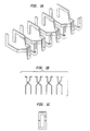
- Fig. 1 shows perspective, top, and side views of the conductors of a prior art 110-type patch plug.
- Fig. 2 shows a schematic diagram of the cable and mating ends of a prior art 110-type patch plug.
- a 110 patch plug has up to four pairs of conductors, each pair (T i , R i ) corresponding to a single balanced transmission path. Due to the proximity of the transmission paths within plugs (such as the 110 patch cord plug), signals in one transmission path can induce crosstalk in one or more adjacent transmission paths within the same plug.
- signals in the transmission path transmitted through TIP contact T 2 and RING contact R 2 can induce crosstalk in the transmission path consisting of TIP contact T 1 and RING contact R 1 , as well as in the transmission path consisting of TIP contact T 3 and RING contact R 3 .
- plugs such as patch cord plugs
- their accompanying receptacles such as connecting blocks
- connecting blocks that are designed to have low crosstalk between the transmission paths of multi-wire circuits.
- Previous attempts at reducing crosstalk have involved increasing the distance between transmission paths (i.e., from one pair of conductors to another) and/or decreasing the distance within each transmission path (i.e., between the two conductors of a single pair).
- Another approach is to introduce opposing crosstalk that is out of phase with the existing crosstalk. This is often done by designing a cross-over (i.e., a physical crossing of one conductor over another) in one or more pairs of conductors, while possibly leaving other pairs of conductors without a cross-over.
- the patch plug of Fig. 1 shows cross-over within each pair of conductors.
- One aspect of the present invention is a novel design for electrical connectors, such as patch plugs and connecting blocks, that have low crosstalk between transmission paths transmitted through such a connector.
- Embodiments of the present invention are directed to one or more low-crosstalk electrical connectors comprising four or more conductors adapted to carry two or more transmission paths.
- Each transmission path uses two types of conductors to carry a balanced signal, wherein parts of like conductors are grouped together, and unlike groups are separated from one another.
- the present invention is directed to electrical connectors, such as patch cord plugs and connecting blocks, that are designed to have low crosstalk between transmission paths.
- the cable ends of such electrical connectors are configured such that those contacts corresponding to like signals of one type (e.g., TIP signals) are grouped together and separated from those conductors corresponding to like signals of another type (e.g., RING signals).
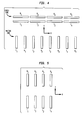
- Fig. 3 shows a perspective view of the conductors of a patch plug, in accordance with one embodiment of the present invention.
- Fig. 4 shows a schematic diagram of the cable and mating ends of the patch plug of Fig. 3.
- the patch plug is designed for voice and data signal transmission applications and has up to four pairs of TIP and RING cable-end contacts, where the contacts are configured such that:
- the inventors have found that the configuration of the cable-end plug contacts shown in Figs. 3-4 reduces the amount of crosstalk in a mated patch-plug/connecting-block configuration between different TIP-RING transmission paths.
- the measured level of near-end crosstalk loss was better than 55dB at 100MHz.
- Near-end crosstalk in the patch plug of Figs. 1-2 results mostly from electromagnetic (e.g., capacitive and/or inductive) coupling between unlike conductors of adjacent TIP-RING pairs.
- crosstalk between the first TIP-RING path and the second TIP-RING path may result primarily from electromagnetic coupling between RING contact R 1 of the first TIP-RING path and the adjacent TIP contact T 2 of the second TIP-RING path.
- the configuration of the patch plug of Figs. 3-4 reduces crosstalk that would otherwise result from electromagnetic coupling between unlike conductors of adjacent TIP-RING pairs at the mating end by increasing the capacitive and/or inductive coupling between like conductors of adjacent pairs at the cable end (e.g., between TIP contact T 1 and TIP contact T 2 and between RING contact R 1 and RING contact R 2 ).
- the increased electromagnetic coupling between like conductors at one end in Figs. 3-4 opposes the electromagnetic coupling between unlike conductors of adjacent pairs at the other end (e.g., between RING contact R 1 and TIP contact T 2 of Fig. 4), thereby resulting in a relatively low level of crosstalk between the two TIP-RING paths of two adjacent transmission paths.
- the crosstalk compensation in patch plugs of the present invention can be made sufficient to oppose and substantially reduce by cancellation the crosstalk generated in a mated combination of the patch cord plug and connecting block.
- the same type of cancellation between adjacent transmission TIP-RING pairs can be achieved by abutting 1, 2, 3, or 4 pair plugs of the same basic crosstalk-canceling construction.
- the shapes, heights, widths, and separation distances along both X and Y directions can be selected to achieve the desired level of crosstalk reduction.
- the cable-end contacts need not be rectangular in shape.
- the configuration of Figs. 3-4 may be adjusted as necessary to ensure that the capacitive and/or inductive coupling between like conductors in one area opposes the capacitive and/or inductive coupling between unlike conductors in another area to a sufficient degree to reduce crosstalk to an acceptable level.
- Fig. 5 shows a schematic diagram of the cable-end contacts of a patch plug, according to an alternative embodiment of the present invention.
- the alternative configuration of Fig. 5 would tend to generate electromagnetic coupling between like conductors that opposes the electromagnetic coupling between unlike conductors and therefore reduce crosstalk between transmission paths carried by the plug. It will be understood that additional alternative configurations fall within the scope of the present invention.
- embodiments of the present invention may have more or less than four pairs of TIP-RING contacts, and that the resulting plugs may be used for applications other than voice or data signal transmission.
- the grouping of like conductors is applied to the cable end of the connector, which preferably can be mated, at its mating end, to a 110-type connecting block. It will be understood that, in alternative embodiments, the grouping of like conductors may be applied to the mating end of the connector rather than the cable end. Obviously, the mating ends of such connectors would not conform to the requirements of 110-type connectors.
Abstract
Description
- The four TIP contacts (T1-T4) are grouped together (i.e., one next to the other) in the X direction;
- The four RING contacts (R1-R4) are grouped together in the X direction;
- The group of RING contacts is separated from the group of TIP contacts in the Y direction; and
- For each pair of TIP and RING contacts (Ti, Ri), the TIP contact Ti is positioned opposite the RING contact Ri in the Y direction.
Claims (7)
- One or more low-crosstalk electrical connectors comprising four or more conductors adapted to carry two or more transmission paths, each transmission path using two types of conductors to carry a balanced signal, wherein parts of like conductors are grouped together, and unlike groups are separated from one another.
- The invention of claim 1, wherein the connector is a plug and each conductor has a mating contact at one end and a contact adapted to receive a cable conductor at the other end.
- The invention of claim 1, wherein the connector is a receptacle adapted to receive a plug and each conductor is adapted to mate with a mating contact of the plug at a first end and to receive a cable conductor at a second end.
- The invention of claim 1, wherein the connector comprises two or more pairs of conductors, each pair of conductors comprising a TIP conductor and a RING conductor, shaped such that cable ends of the TIP conductors are grouped together, cable ends of the RING conductors are grouped together, and the group of TIP-conductor cable ends is separated from the group of RING-conductor cable ends.
- The invention of claim 1, wherein, cable ends of the conductors are configured such that, when signals are transmitted over one or more transmission path, electromagnetic coupling between like-conductor cable ends is generated that opposes electromagnetic coupling between unlike-conductor mating ends, when the mating ends of the connector are mated to contacts of a mating connector.
- The invention of claim 5, wherein the electromagnetic coupling comprises at least one of capacitive coupling and inductive coupling.
- The invention of claim 6, wherein:the connector is one of:(1) a plug, wherein each conductor has a mating contact at one end and a contact adapted to receive a cable conductor at the other end; and(2) a receptacle adapted to receive a plug and each conductor is adapted to mate with a mating contact of the plug at a first end and to receive a cable conductor at a second end; andthe connector comprises two or more pairs of conductors, each pair of conductors comprising a TIP conductor and a RING conductor, wherein the conductors are shaped such that:cable ends of the TIP conductors are grouped together;cable ends of the RING conductors are grouped together; andthe group of TIP-conductor cable ends is separated from the group of RING-conductor cable ends.
Applications Claiming Priority (2)
| Application Number | Priority Date | Filing Date | Title |
|---|---|---|---|
| US858234 | 1997-05-19 | ||
| US08/858,234 US6065994A (en) | 1996-06-21 | 1997-05-19 | Low-crosstalk electrical connector grouping like conductors together |
Publications (3)
| Publication Number | Publication Date |
|---|---|
| EP0880202A2 true EP0880202A2 (en) | 1998-11-25 |
| EP0880202A3 EP0880202A3 (en) | 1999-11-03 |
| EP0880202B1 EP0880202B1 (en) | 2003-03-26 |
Family
ID=25327818
Family Applications (1)
| Application Number | Title | Priority Date | Filing Date |
|---|---|---|---|
| EP98303700A Expired - Lifetime EP0880202B1 (en) | 1997-05-19 | 1998-05-12 | Low-crosstalk electrical connector grouping like conductors together |
Country Status (3)
| Country | Link |
|---|---|
| US (1) | US6065994A (en) |
| EP (1) | EP0880202B1 (en) |
| JP (1) | JPH10335002A (en) |
Cited By (6)
| Publication number | Priority date | Publication date | Assignee | Title |
|---|---|---|---|---|
| EP1049217A1 (en) * | 1999-04-27 | 2000-11-02 | Lucent Technologies Inc. | Connector having internal crosstalk compensation |
| US6250968B1 (en) | 1999-07-14 | 2001-06-26 | Berg Technology, Inc. | Electrical connector system with cross-talk compensation |
| US6358094B1 (en) | 1999-09-15 | 2002-03-19 | Fci Americas Technology, Inc. | Low inductance connector with enhanced capacitively coupled contacts for power applications |
| US6468090B2 (en) | 1999-09-15 | 2002-10-22 | Fci Americas Technology, Inc. | Low inductance power connector and method of reducing inductance in an electrical connector |
| US6511344B2 (en) | 2001-07-02 | 2003-01-28 | Fci Americas Technology, Inc. | Double-deck electrical connector with cross-talk compensation |
| WO2014014869A3 (en) * | 2012-07-16 | 2014-07-03 | Commscope, Inc. Of North Carolina | Balanced pin and socket connectors |
Families Citing this family (18)
| Publication number | Priority date | Publication date | Assignee | Title |
|---|---|---|---|---|
| US6189133B1 (en) * | 1998-05-14 | 2001-02-13 | International Business Machines Corporation | Coupling noise reduction technique using reset timing |
| DE19844869A1 (en) * | 1998-09-30 | 2000-05-11 | Alcatel Sa | Contact element for connecting a ribbon cable with round conductors and rotary connectors with such a contact element |
| US6309240B1 (en) * | 1998-12-21 | 2001-10-30 | Avaya Technology Corp. | Terminal strip for maintaining tip/ring orientation standards |
| US6089923A (en) * | 1999-08-20 | 2000-07-18 | Adc Telecommunications, Inc. | Jack including crosstalk compensation for printed circuit board |
| US6923672B1 (en) * | 2004-04-15 | 2005-08-02 | Surtec Industries Inc. | Patch plug |
| US7503798B2 (en) * | 2005-06-03 | 2009-03-17 | Commscope, Inc. Of North Carolina | Cross connect systems with self-compensating balanced connector elements |
| US20070293097A1 (en) * | 2006-06-15 | 2007-12-20 | Tyco Electronics Corporation | Modular plug electrical connector |
| US7794290B1 (en) | 2009-07-21 | 2010-09-14 | Adtran, Inc. | Communications connector configured for low crosstalk |
| US8437469B1 (en) | 2010-01-25 | 2013-05-07 | Adtran, Inc. | Electrical protection device configured to reduce crosstalk caused by fuses |
| US9112309B1 (en) * | 2014-01-29 | 2015-08-18 | Yfc-Boneagle Electric Co., Ltd. | Network connector socket |
| JP6452512B2 (en) * | 2015-03-18 | 2019-01-16 | 日本航空電子工業株式会社 | connector |
| GB2547958B (en) | 2016-03-04 | 2019-12-18 | Commscope Technologies Llc | Two-wire plug and receptacle |
| JP2019175541A (en) * | 2016-08-25 | 2019-10-10 | アルプスアルパイン株式会社 | Twisted-pair cable connector |
| CN115313081A (en) | 2017-04-24 | 2022-11-08 | 康普技术有限责任公司 | Connector for single twisted conductor pairs |
| EP3635823A4 (en) | 2017-06-08 | 2021-03-03 | Commscope Technologies LLC | Connectors for a single twisted pair of conductors |
| US11296463B2 (en) | 2018-01-26 | 2022-04-05 | Commscope Technologies Llc | Connectors for a single twisted pair of conductors |
| EP3759765A4 (en) | 2018-02-26 | 2022-04-13 | CommScope Technologies LLC | Connectors and contacts for a single twisted pair of conductors |
| CN113574748A (en) | 2019-03-15 | 2021-10-29 | 康普技术有限责任公司 | Connector and contact for single twisted conductor pairs |
Family Cites Families (8)
| Publication number | Priority date | Publication date | Assignee | Title |
|---|---|---|---|---|
| US5299956B1 (en) * | 1992-03-23 | 1995-10-24 | Superior Modular Prod Inc | Low cross talk electrical connector system |
| US5226835A (en) * | 1992-08-06 | 1993-07-13 | At&T Bell Laboratories | Patch plug for cross-connect equipment |
| GB2270422B (en) * | 1992-09-04 | 1996-04-17 | Pressac Ltd | Method and apparatus for cross talk cancellation |
| US5362257A (en) * | 1993-07-08 | 1994-11-08 | The Whitaker Corporation | Communications connector terminal arrays having noise cancelling capabilities |
| GB2271678B (en) * | 1993-12-03 | 1994-10-12 | Itt Ind Ltd | Electrical connector |
| JP3727373B2 (en) * | 1995-03-03 | 2005-12-14 | 三菱電機株式会社 | Shift control device for automatic transmission |
| US5601447A (en) * | 1995-06-28 | 1997-02-11 | Reed; Carl G. | Patch cord assembly |
| US5716237A (en) * | 1996-06-21 | 1998-02-10 | Lucent Technologies Inc. | Electrical connector with crosstalk compensation |
-
1997
- 1997-05-19 US US08/858,234 patent/US6065994A/en not_active Expired - Lifetime
-
1998
- 1998-05-12 EP EP98303700A patent/EP0880202B1/en not_active Expired - Lifetime
- 1998-05-18 JP JP10135705A patent/JPH10335002A/en active Pending
Non-Patent Citations (1)
| Title |
|---|
| None |
Cited By (13)
| Publication number | Priority date | Publication date | Assignee | Title |
|---|---|---|---|---|
| EP1049217A1 (en) * | 1999-04-27 | 2000-11-02 | Lucent Technologies Inc. | Connector having internal crosstalk compensation |
| EP1069655A3 (en) * | 1999-07-14 | 2002-04-17 | Berg Electronics Manufacturing B.V. | Electrical connector system with cross-talk compensation |
| US6250968B1 (en) | 1999-07-14 | 2001-06-26 | Berg Technology, Inc. | Electrical connector system with cross-talk compensation |
| US6821128B2 (en) | 1999-09-15 | 2004-11-23 | Fci Americas Technology, Inc. | Low inductance power connector and method of reducing inductance in an electrical connector |
| US6468090B2 (en) | 1999-09-15 | 2002-10-22 | Fci Americas Technology, Inc. | Low inductance power connector and method of reducing inductance in an electrical connector |
| US6358094B1 (en) | 1999-09-15 | 2002-03-19 | Fci Americas Technology, Inc. | Low inductance connector with enhanced capacitively coupled contacts for power applications |
| US6511344B2 (en) | 2001-07-02 | 2003-01-28 | Fci Americas Technology, Inc. | Double-deck electrical connector with cross-talk compensation |
| WO2014014869A3 (en) * | 2012-07-16 | 2014-07-03 | Commscope, Inc. Of North Carolina | Balanced pin and socket connectors |
| KR20150034184A (en) * | 2012-07-16 | 2015-04-02 | 콤스코프 인코포레이티드 오브 노스 캐롤라이나 | Balanced pin and socket connectors |
| US9407043B2 (en) | 2012-07-16 | 2016-08-02 | Commscope, Inc. Of North Carolina | Balanced pin and socket connectors |
| US9972940B2 (en) | 2012-07-16 | 2018-05-15 | Commscope, Inc. Of North Carolina | Balanced pin and socket connectors |
| US10411409B2 (en) | 2012-07-16 | 2019-09-10 | Commscope, Inc. Of North Carolina | Balanced pin and socket connectors |
| US11303068B2 (en) | 2012-07-16 | 2022-04-12 | Commscope, Inc. Of North Carolina | Balanced pin and socket connectors |
Also Published As
| Publication number | Publication date |
|---|---|
| EP0880202A3 (en) | 1999-11-03 |
| JPH10335002A (en) | 1998-12-18 |
| EP0880202B1 (en) | 2003-03-26 |
| US6065994A (en) | 2000-05-23 |
Similar Documents
| Publication | Publication Date | Title |
|---|---|---|
| EP0880202B1 (en) | Low-crosstalk electrical connector grouping like conductors together | |
| US5915989A (en) | Connector with counter-balanced crosswalk compensation scheme | |
| AU737453B2 (en) | Electrical connector having time-delayed signal compensation | |
| EP0858684B1 (en) | Reduced cross talk electrical connector | |
| AU2010258637B2 (en) | Communications plugs having capacitors that inject offending crosstalk after a plug-jack mating point and related connectors and methods | |
| US9680259B2 (en) | Electrical jack with a plurality of parallel and overlapping capacitive plates | |
| US7154049B2 (en) | Apparatus for crosstalk compensation in a telecommunications connector | |
| US7559789B2 (en) | Communications connectors with self-compensating insulation displacement contacts | |
| EP0811258B1 (en) | High frequency modular plug and cable assembly | |
| US6796847B2 (en) | Electrical connector for telecommunications applications | |
| EP2082458B1 (en) | Connecting hardware with multi-stage inductive and capacitive crosstalk compensation | |
| AU2007201106B9 (en) | Electrical Connector | |
| US20140315434A1 (en) | Electrical connectors having open-ended conductors | |
| EP1246318A2 (en) | Dual reactance low noise modular connector insert | |
| US8313338B2 (en) | Electrical connector | |
| US8864532B2 (en) | Communications jacks having low crosstalk and/or solder-less wire connection assemblies | |
| US7651380B2 (en) | Modular plugs and outlets having enhanced performance contacts | |
| WO2007123834A1 (en) | Communications connectors with jackwire contacts and printed circuit boards | |
| EP2765656B1 (en) | Patch cord | |
| US20020001999A1 (en) | Reduced crosstalk modular plug and patch cord incorporating the same | |
| US7172466B2 (en) | Dual reactance low noise modular connector insert | |
| EP3175515B1 (en) | Communications connectors including low impedance transmission line segments that improve return loss | |
| US20040119549A1 (en) | Cross talk compensation circuit | |
| US6017240A (en) | Modular plug having low electrical cross talk and metallic contact for use therein | |
| AU752830B2 (en) | Low-crosstalk electrical connector grouping like conductors together |
Legal Events
| Date | Code | Title | Description |
|---|---|---|---|
| PUAI | Public reference made under article 153(3) epc to a published international application that has entered the european phase |
Free format text: ORIGINAL CODE: 0009012 |
|
| AK | Designated contracting states |
Kind code of ref document: A2 Designated state(s): GB NL |
|
| AX | Request for extension of the european patent |
Free format text: AL;LT;LV;MK;RO;SI |
|
| PUAL | Search report despatched |
Free format text: ORIGINAL CODE: 0009013 |
|
| AK | Designated contracting states |
Kind code of ref document: A3 Designated state(s): AT BE CH CY DE DK ES FI FR GB GR IE IT LI LU MC NL PT SE |
|
| AX | Request for extension of the european patent |
Free format text: AL;LT;LV;MK;RO;SI |
|
| 17P | Request for examination filed |
Effective date: 20000419 |
|
| AKX | Designation fees paid |
Free format text: GB NL |
|
| REG | Reference to a national code |
Ref country code: DE Ref legal event code: 8566 |
|
| 17Q | First examination report despatched |
Effective date: 20011016 |
|
| GRAG | Despatch of communication of intention to grant |
Free format text: ORIGINAL CODE: EPIDOS AGRA |
|
| GRAG | Despatch of communication of intention to grant |
Free format text: ORIGINAL CODE: EPIDOS AGRA |
|
| GRAH | Despatch of communication of intention to grant a patent |
Free format text: ORIGINAL CODE: EPIDOS IGRA |
|
| GRAH | Despatch of communication of intention to grant a patent |
Free format text: ORIGINAL CODE: EPIDOS IGRA |
|
| GRAA | (expected) grant |
Free format text: ORIGINAL CODE: 0009210 |
|
| RIC1 | Information provided on ipc code assigned before grant |
Ipc: 7H 01R 24/00 A |
|
| AK | Designated contracting states |
Designated state(s): GB NL |
|
| REG | Reference to a national code |
Ref country code: GB Ref legal event code: FG4D |
|
| PLBE | No opposition filed within time limit |
Free format text: ORIGINAL CODE: 0009261 |
|
| STAA | Information on the status of an ep patent application or granted ep patent |
Free format text: STATUS: NO OPPOSITION FILED WITHIN TIME LIMIT |
|
| 26N | No opposition filed |
Effective date: 20031230 |
|
| PGFP | Annual fee paid to national office [announced via postgrant information from national office to epo] |
Ref country code: NL Payment date: 20100524 Year of fee payment: 13 |
|
| PGFP | Annual fee paid to national office [announced via postgrant information from national office to epo] |
Ref country code: GB Payment date: 20100525 Year of fee payment: 13 |
|
| REG | Reference to a national code |
Ref country code: NL Ref legal event code: V1 Effective date: 20111201 |
|
| GBPC | Gb: european patent ceased through non-payment of renewal fee |
Effective date: 20110512 |
|
| PG25 | Lapsed in a contracting state [announced via postgrant information from national office to epo] |
Ref country code: NL Free format text: LAPSE BECAUSE OF NON-PAYMENT OF DUE FEES Effective date: 20111201 |
|
| PG25 | Lapsed in a contracting state [announced via postgrant information from national office to epo] |
Ref country code: GB Free format text: LAPSE BECAUSE OF NON-PAYMENT OF DUE FEES Effective date: 20110512 |